
Rapid-Hardening and High-Strength Steel-Fiber-Reinforced Concrete: Effects of Curing Ages and Strain Rates on Compressive Performance

Abstract
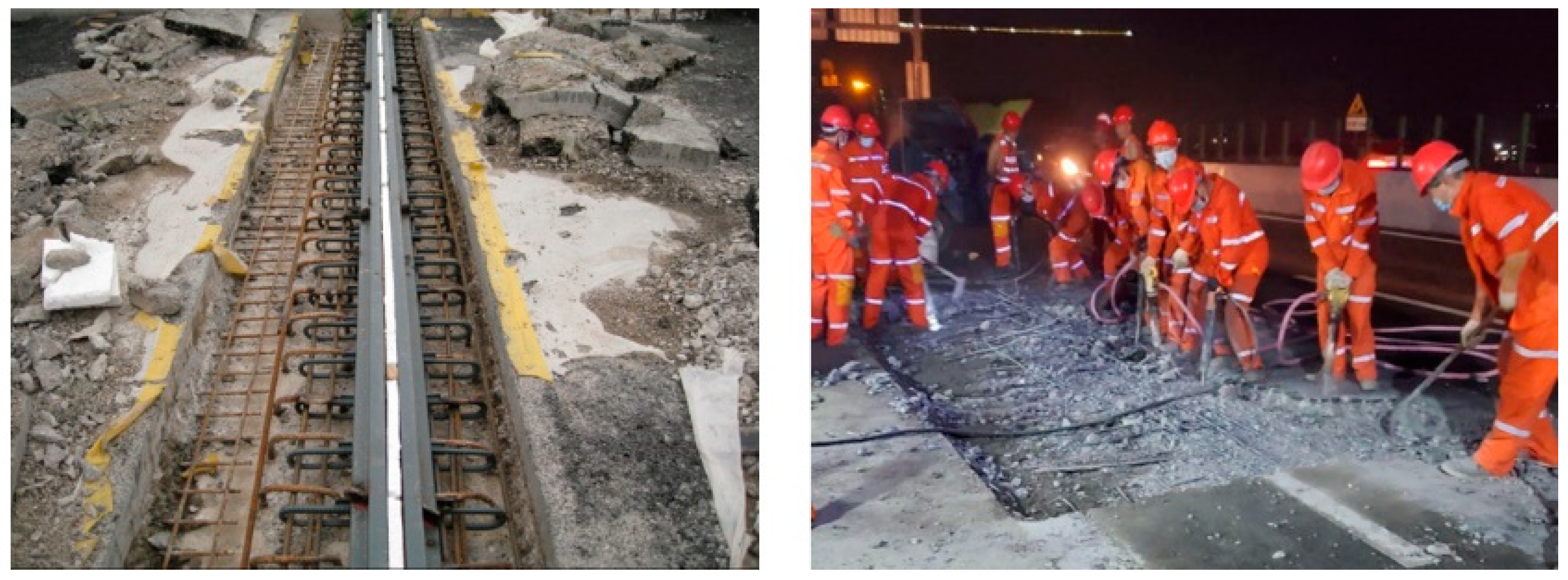
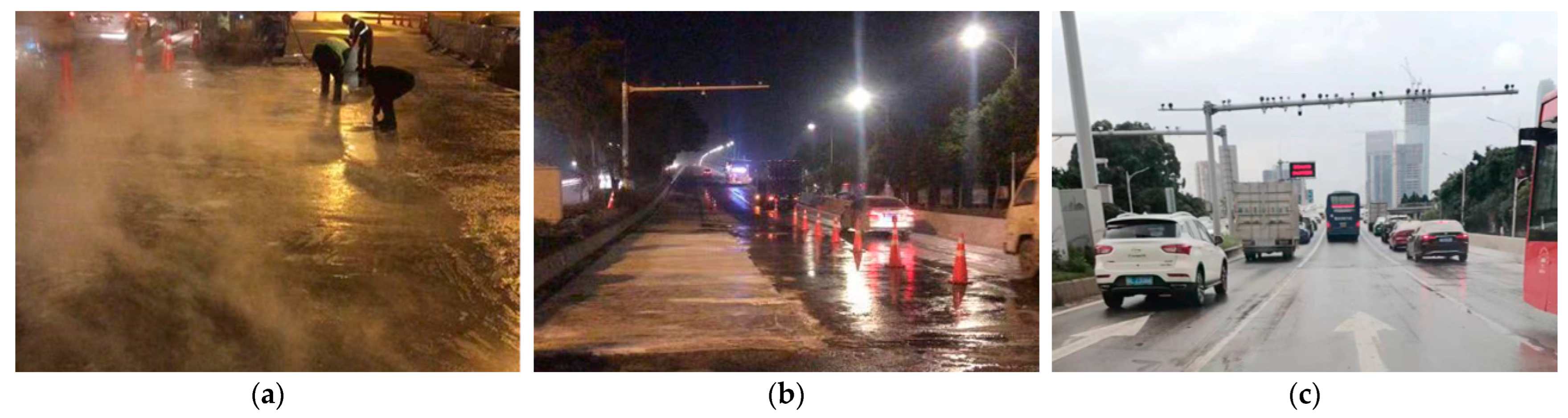
:1. Introduction
2. Experimental Program
2.1. Specimen Design
2.2. Raw Materials
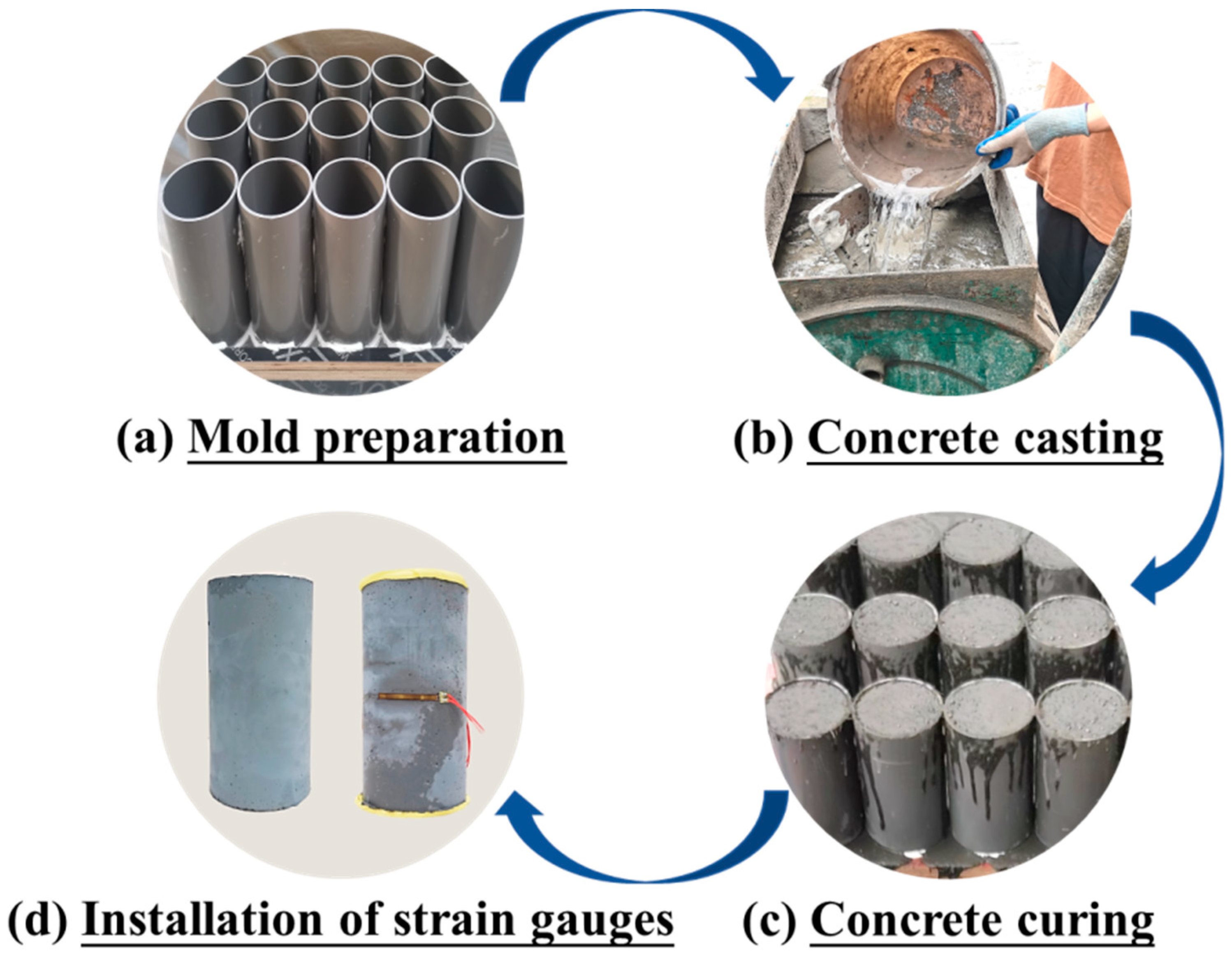
2.3. Specimen Preparation
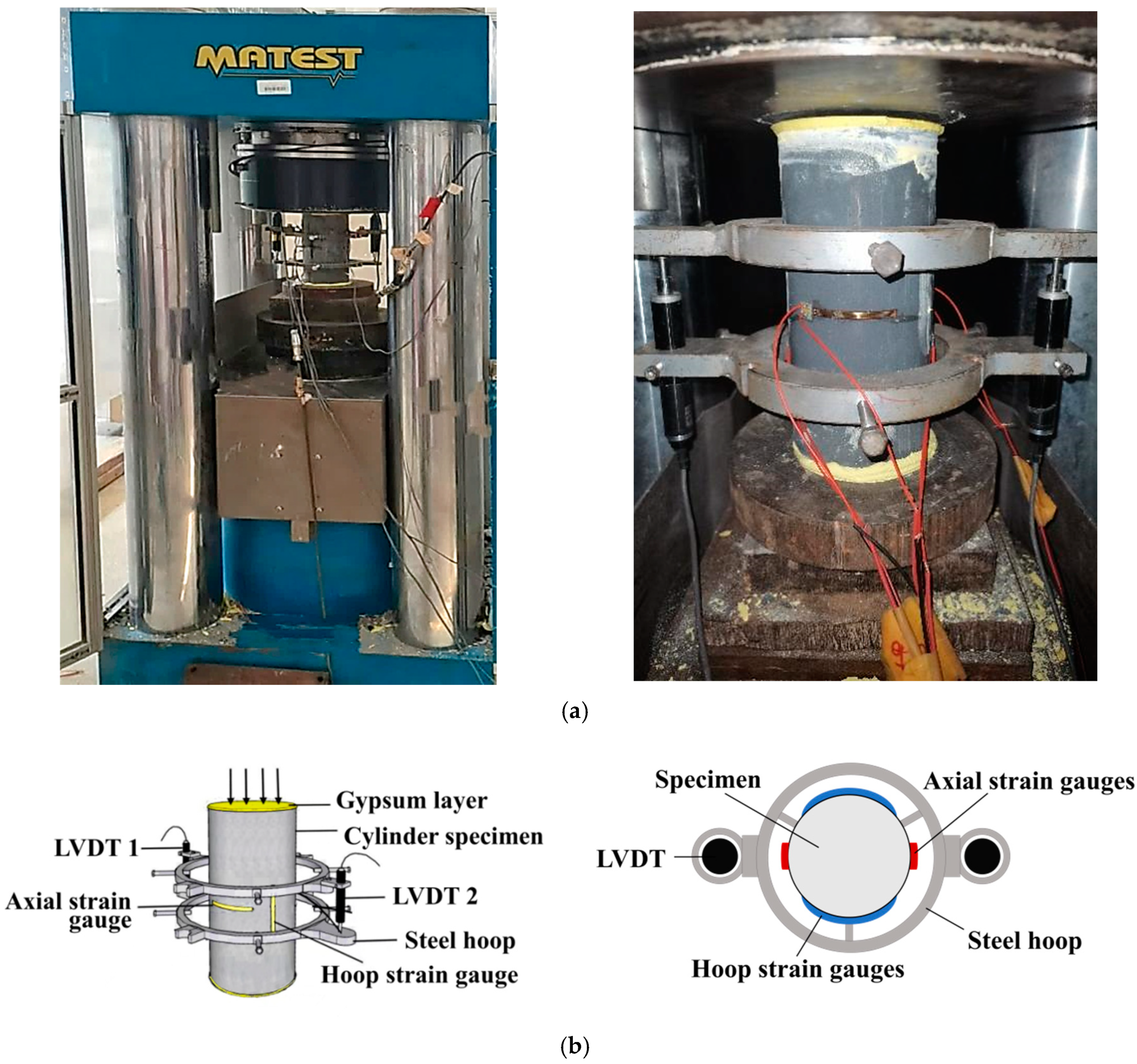
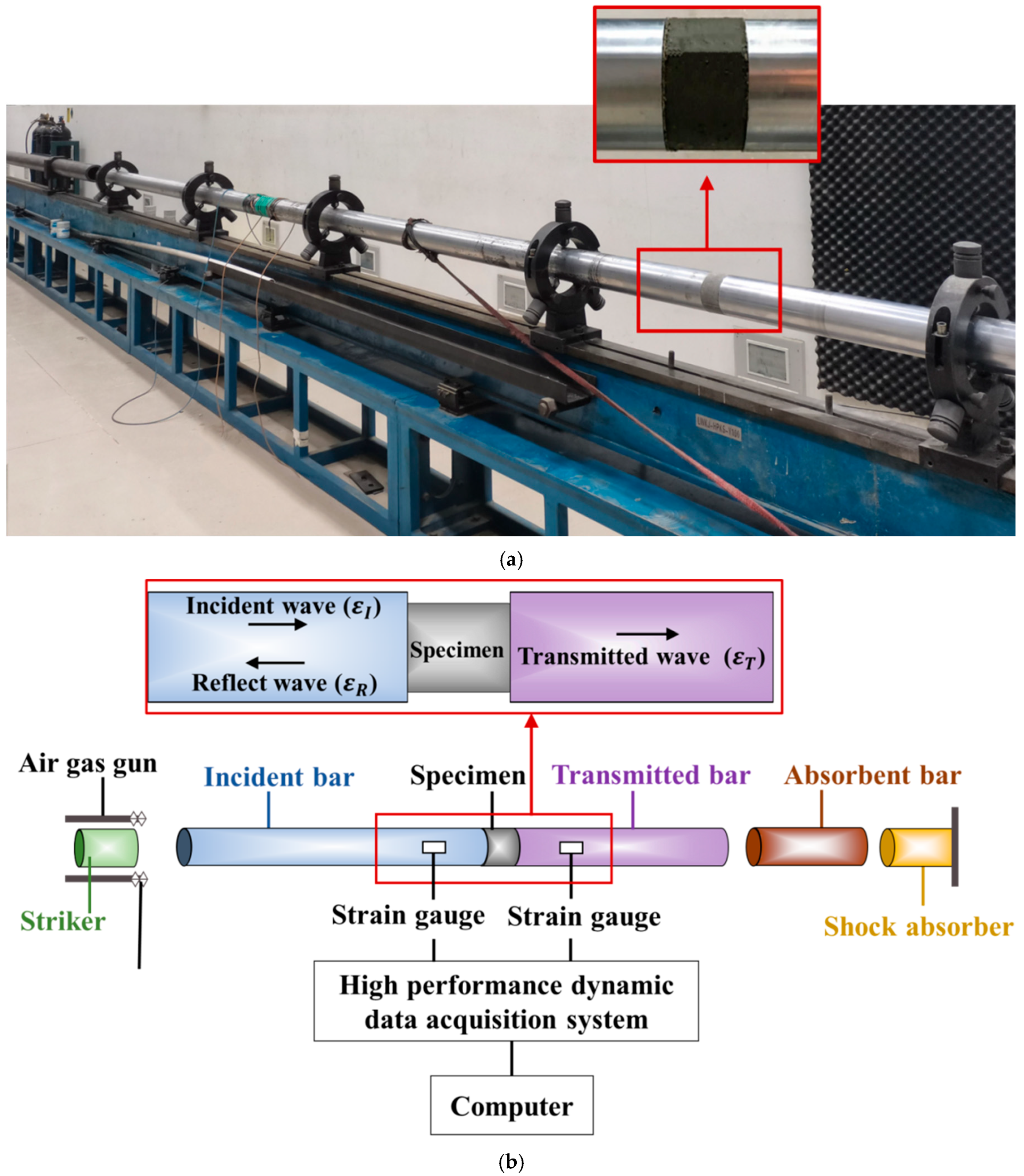
2.4. Test Setup and Instrumentation
Quasi-Static Compression Tests
3. Results and Discussion of Quasi-Static Compression Test
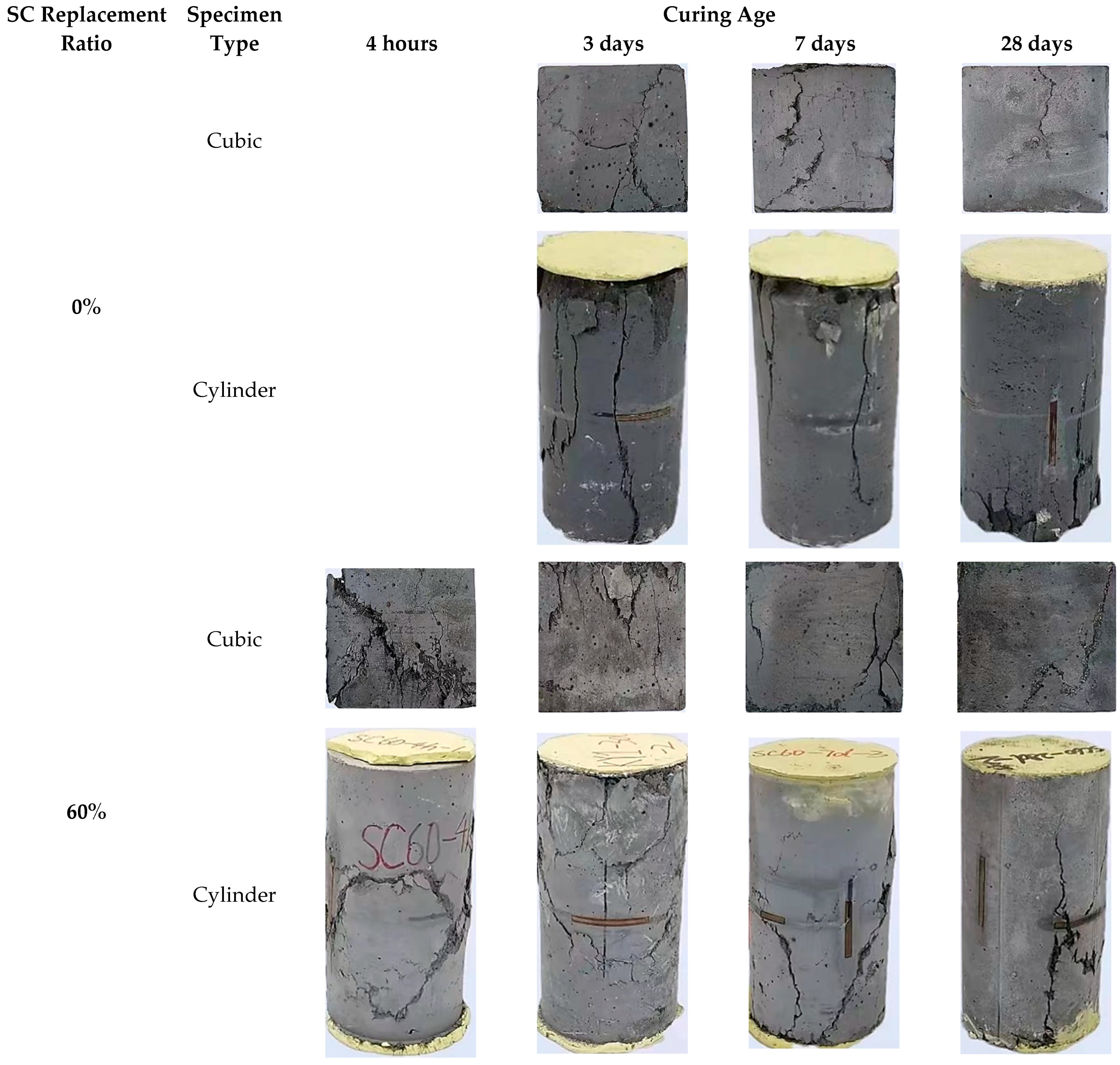
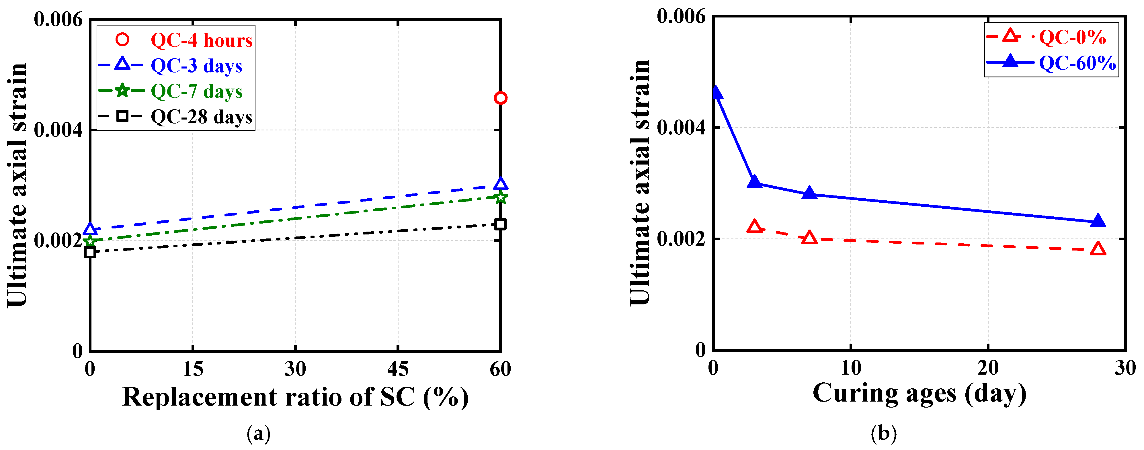
3.1. Failure Modes and Ultimate Conditions
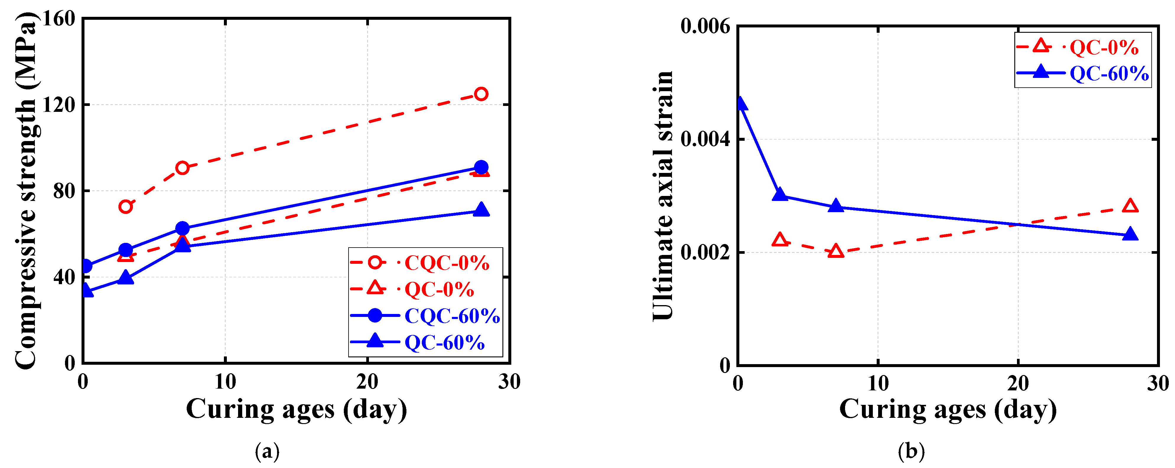
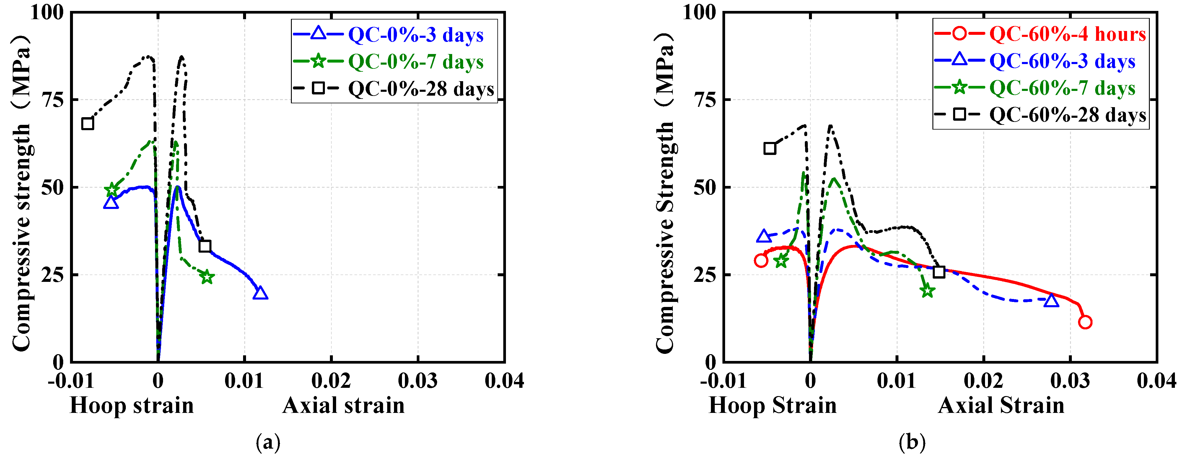
3.2. Stress–Strain Responses
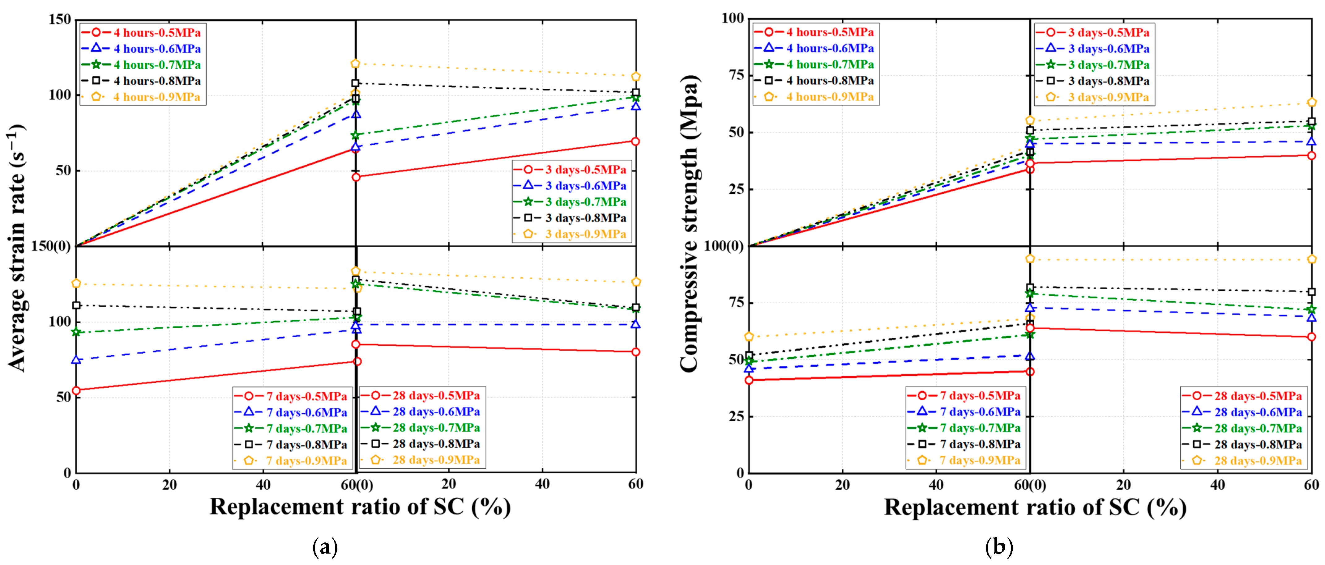
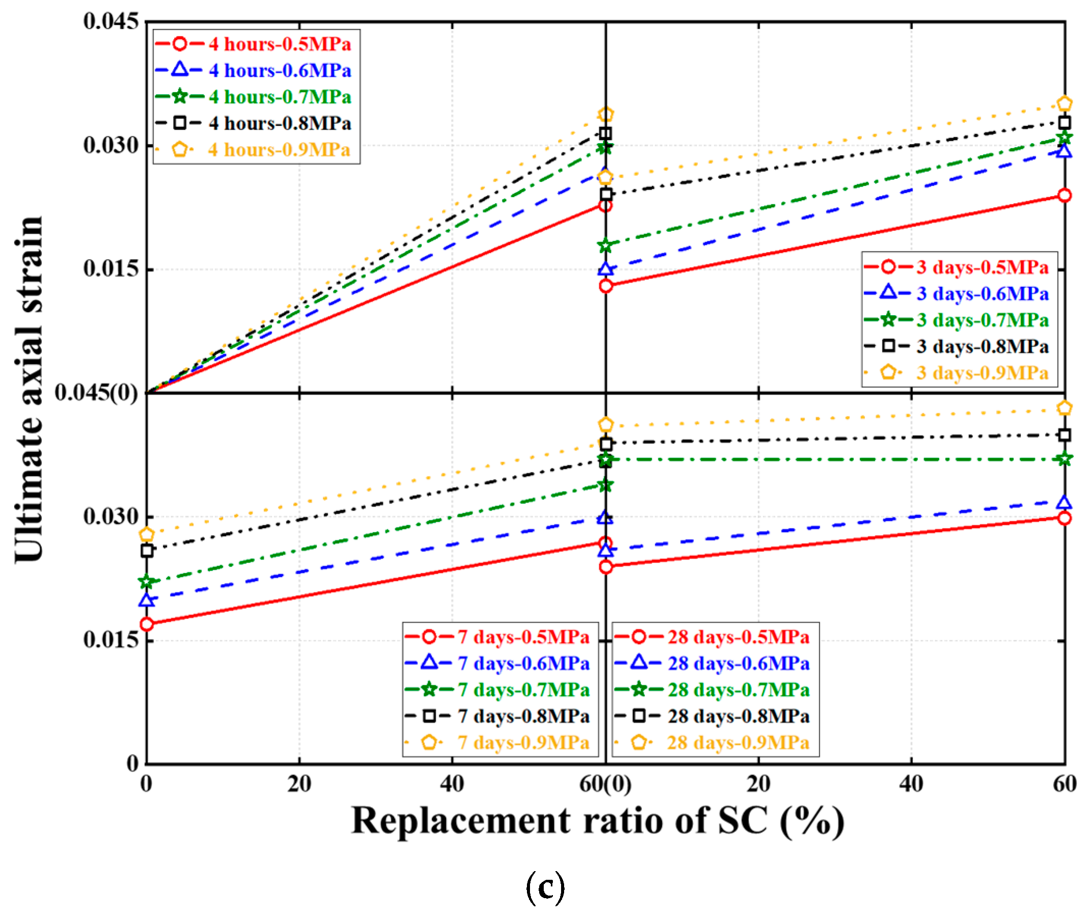
4. Results and Discussion of Dynamic Compression Tests
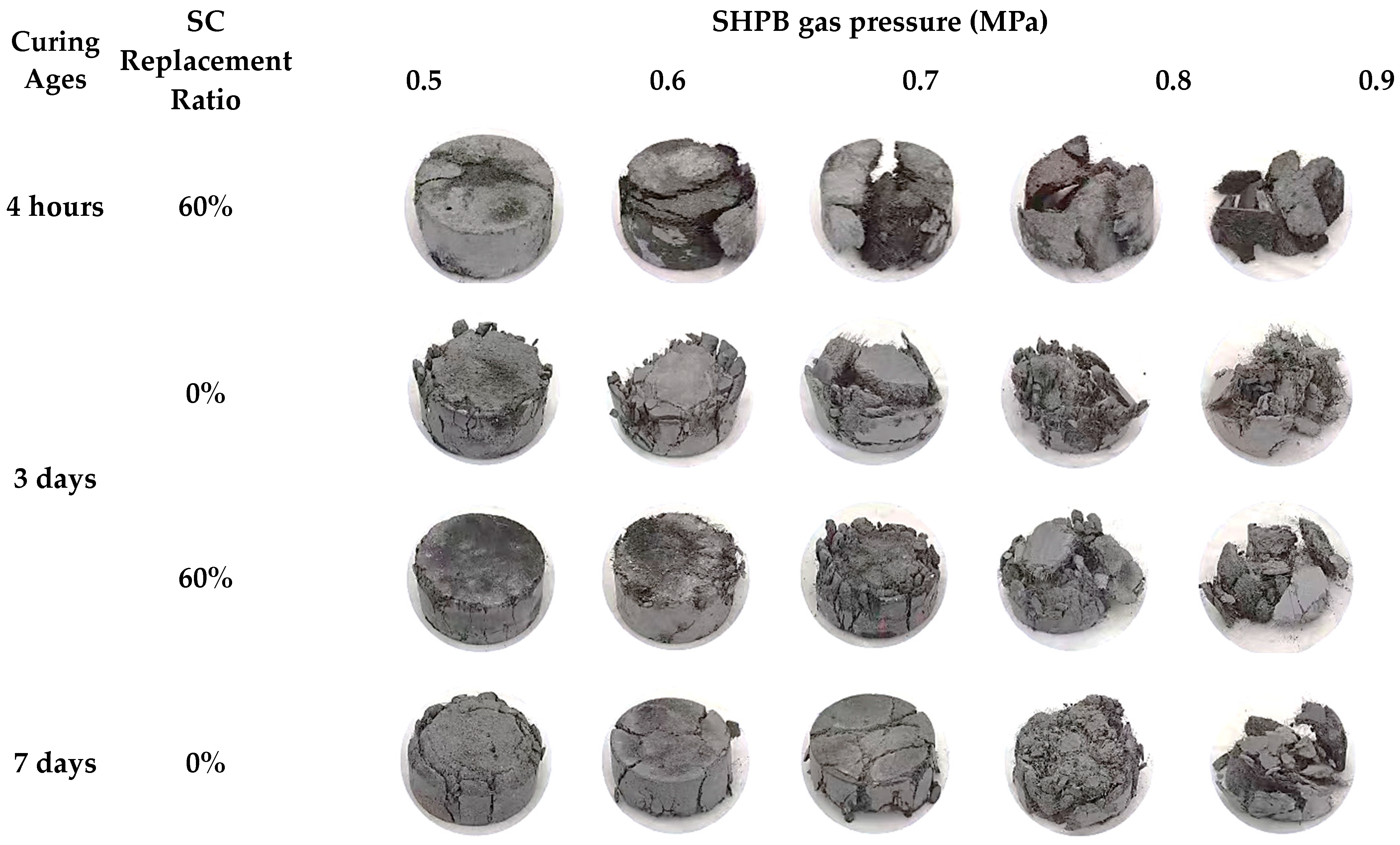
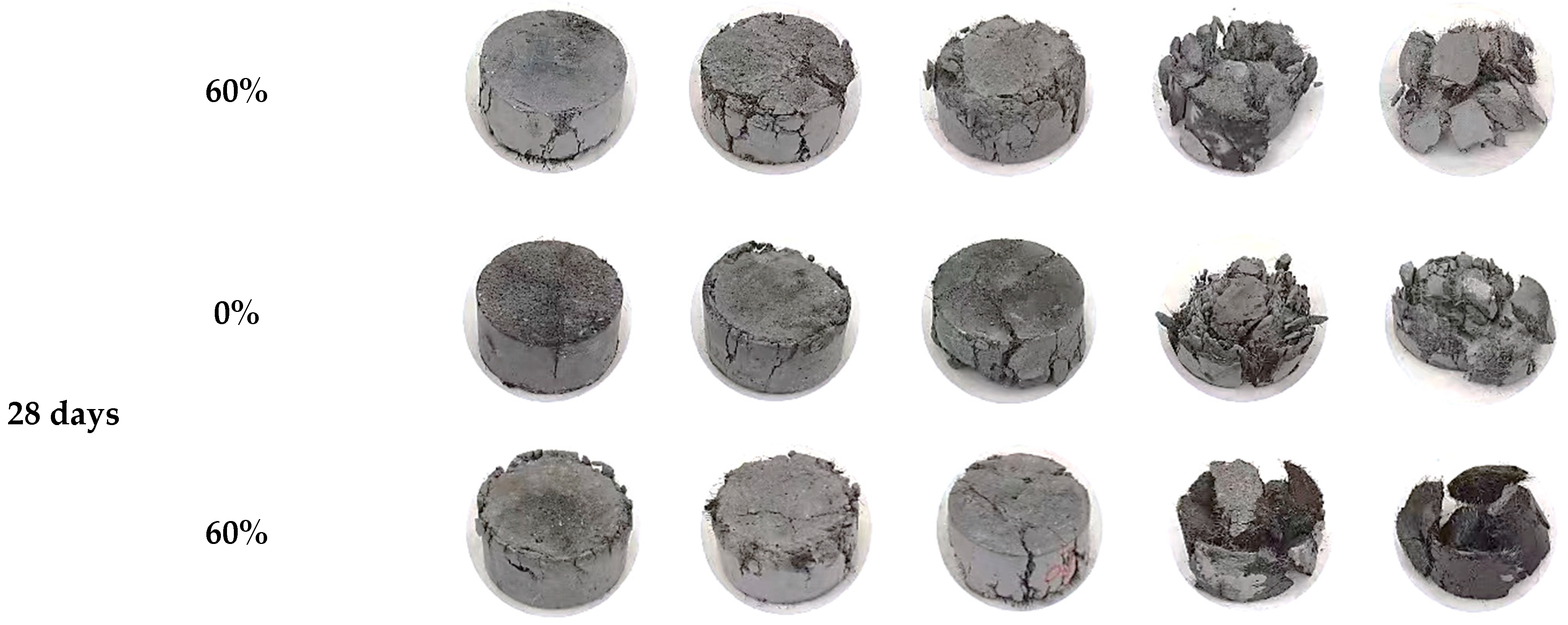
Failure Modes and Ultimate Conditions
5. Conclusions
- (1)
- Rapid-hardening HSFRC exhibited high early strength characteristics: the quasi-static compressive strengths of the cubes and cylinders at 4 h of curing age reached 45.16 and 33.14 MPa, respectively, which were 55 and 48% of their corresponding 28-day age strengths; in addition, the FBD specimen at 4 days of curing age had a dynamic compressive strength of up to 43.97 MPa, roughly 0.4 times their corresponding 28-day age strength.
- (2)
- The introduction of SC resulted in an increase in the strain rate sensitivity of HSFRC, where the strain rate sensitivity of rapid-hardening HSFRC increased with the increasing curing age and strain rate.
- (3)
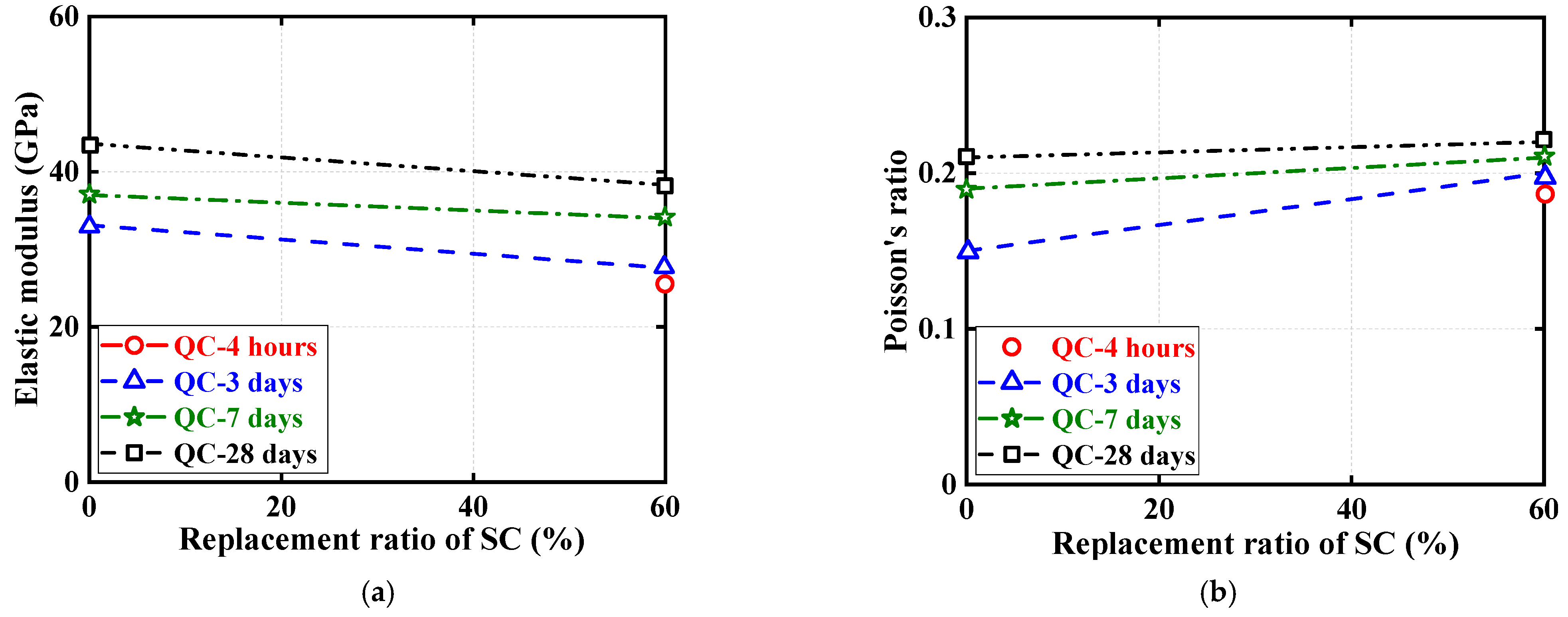
- The compressive strength, elastic modulus, and Poisson’s ratio of rapid-hardening HSFRC were inferior to those of their conventional counterparts in both quasi-static and dynamic compressive loading, but rapid-hardening HSFRC’s postpeak deformation capacity was significantly better than that of the conventional counterparts.
- (4)
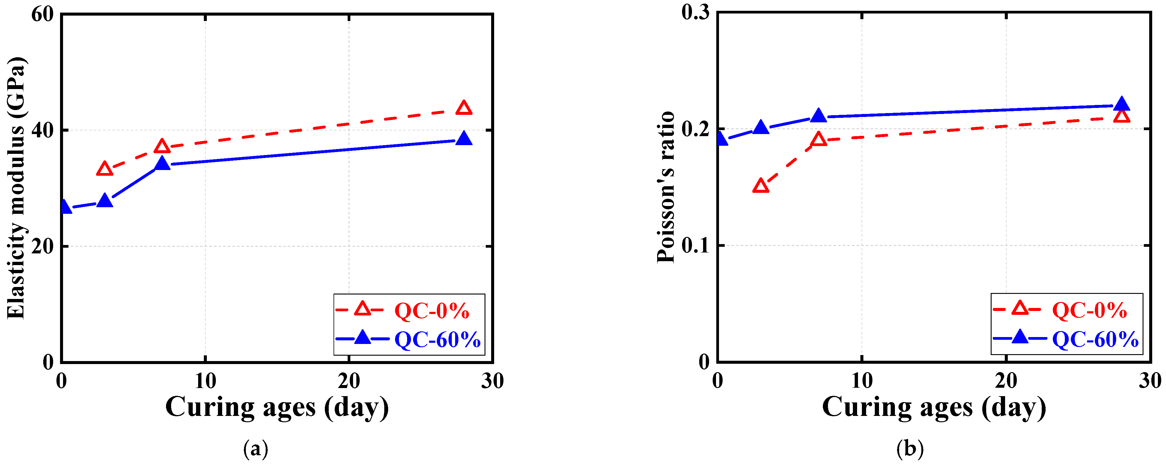
- The elastic modulus and Poisson’s ratio of HSFRC with different cement types under quasi-static compression increased with increasing curing age; the negative relationship between the elastic modulus and curing ages or strain rates was found under dynamic counterparts.
Author Contributions
Funding
Institutional Review Board Statement
Informed Consent Statement
Data Availability Statement
Acknowledgments
Conflicts of Interest
Nomenclature
| Abbreviations | |
| HSFRC | High-strength steel-fiber-reinforced concrete |
| SC | Sulphoaluminate cement |
| SHPB | Split Hopkinson pressure bar |
| FBD | Flattened Brazilian discs |
| CQC | Cubes under quasi-static compression |
| QC | Cylinders under quasi-static compression |
| DC | FBD specimens under dynamic compression |
| h | Hour |
| d | Day |
| LVDT | Linear displacement transducer |
| Symbols | |
| Average strain rate of FBD specimens | |
| Compressive strength of FBD specimens | |
| Strain corresponding to | |
| Time | |
| Propagation speed of one-dimensional stress wave in SHPB | |
| Thickness of FBD specimens | |
| Cross-sectional area of FBD specimens | |
| Strain of reflected wave from incident bar of SHPB | |
| Elastic modulus of SHPB | |
| Cross-sectional area of the SHPB | |
| Strain of incident wave from incident bar of SHPB | |
| Strain of transmitted wave from transmitted bar of SHPB | |
References
- Deng, L.; Yan, W.C.; Zhu, Q.J. Vehicle impact on the deck slab of concrete box-girder bridges due to damaged expansion joints. J. Bridge Eng. 2016, 21, 2. [Google Scholar] [CrossRef]
- Ding, Y.; Zhang, W.; Au, F.T. Effect of dynamic impact at modular bridge expansion joints on bridge design. J. Eng. Struct. 2016, 127, 645–662. [Google Scholar] [CrossRef]
- Gong, J.H.; Ma, Y.W.; Fu, J.Y.; Hu, J.; Ouyang, X.W.; Zhang, Z.H.; Wang, H. Utilization of fibers in ultra-high performance concrete: A review. J. Compos. Part B Eng. 2022, 241, 109995. [Google Scholar] [CrossRef]
- Zhang, J.H.; Wu, Z.Y.; Yu, H.F.; Ma, H.Y.; Da, B. Mesoscopic modeling approach and application for steel fiber reinforced concrete under dynamic loading: A review. J. Eng. 2022, 16, 220–238. [Google Scholar] [CrossRef]
- Yeo, S.H.; Mo, K.H.; Hosen, M.A.; Mahmud, H.B. Properties of cementitious repair materials for concrete pavement. Adv. Mater. Sci. Eng. 2022, 2022, 3057801. [Google Scholar] [CrossRef]
- Yu, R.; Zhang, X.Y.; Hu, Y.W.; Li, J.H.; Zhou, F.J.; Liu, K.N.; Zhang, J.J.; Wang, J.N. Development of a rapid hardening ultra-high performance concrete (R-UHPC): From macro properties to micro structure. Constr. Build. Mater. 2022, 329, 127188. [Google Scholar] [CrossRef]
- Al-musawi, H.; Huang, H.D.; Di Benedetti, M.; Guadagnini, M.; Pilakoutas, K. Effect of shrinkage on rapid hardening plain and recycled steel fiber concrete overlays. Cem. Con. Comp. 2021, 125, 104246. [Google Scholar] [CrossRef]
- Cao, X.Y.; Feng, D.C.; Li, Y. Assessment of various seismic fragility analysis approaches for structures ex-cited by non-stationary stochastic ground motions. Mech. Syst. Signal Process. 2023, 186, 109838. [Google Scholar] [CrossRef]
- Zhao, B.D.; Liu, C.Q.; Wu, H.D.; Ge, Y.H.; Yang, J.J.; Yi, Q. Study on out-of-plane flexural stiffness of unstiffened multi-planar CHS X-joints. Eng. Struct. 2019, 188, 137–146. [Google Scholar] [CrossRef]
- Xiong, Z.; Lin, L.H.; Qiao, S.H.; Li, L.J.; Li, Y.L.; He, S.H.; Li, Z.W.; Liu, F.; Chen, Y.L. Axial performance of seawater sea-sand concrete columns reinforced with basalt fiber-reinforced polymer bars under concentric compressive load. J. Build. Eng. 2022, 47, 103828. [Google Scholar] [CrossRef]
- Sun, J.B.; Lin, S.; Zhang, G.B.; Sun, Y.T.; Zhang, J.F.; Chen, C.F. The effect of graphite and slag on electrical and mechanical properties of electrically conductive cementitious composites. Con. Build. Mat. 2021, 281, 122606. [Google Scholar] [CrossRef]
- Zhao, B.D.; Chen, Y.; Liu, C.Q.; Wu, H.D.; Wang, T.; Wei, X.D. An axial semi-rigid connection model for cross-type transverse branch plate-to-CHS joints. Eng. Struct. 2019, 181, 413–426. [Google Scholar] [CrossRef]
- Feng, W.H.; Tang, Y.C.; He, W.M.; Wei, W.B.; Yang, Y.M. Model dynamic fracture toughness of rubberised concrete using a drop hammer device and split Hopkinson pressure bar. J. Build. Eng. 2022, 48, 103995. [Google Scholar] [CrossRef]
- Cao, X.Y.; Feng, D.C.; Beer, M. Consistent seismic hazard and fragility analysis considering combined capacity-demand uncertainties via probability density evolution method. Struct. Saf. 2023, 103, 102330. [Google Scholar] [CrossRef]
- Fang, S.; Li, L.J.; Luo, Z.P.; Fang, Z.C.; Li, Z.W.; Liu, F.; Wang, H.L.; Xiong, Z. Novel FRP interlocking multi-spiral rein-forced-seawater sea-sand concrete square columns with longitudinal hybrid FRP–steel bars: Monotonic and cyclic axial compressive behaviors. Compos. Struct. 2023, 305, 116487. [Google Scholar] [CrossRef]
- Zhao, B.D.; Ke, K.; Liu, C.Q.; Hong, L. Computational model for the flexural capacity and stiffness of eccentric RHS X-connections under brace out-of-plane bending moment. J. Struct. Eng. 2020, 146, 04019227. [Google Scholar] [CrossRef]
- Cao, X.Y.; Feng, D.C.; Wang, C.L.; Shen, D.J.; Wu, G. A stochastic CSM-based displacement-oriented design strategy for the novel precast SRC-UHPC composite braced-frame in the externally attached seismic retrofitting. Compos. Struct. 2023, 321, 117308. [Google Scholar] [CrossRef]
- Seok, S.H.; So, S. An experimental study on the strength development of ultra-high strength steel fiber reinforced cementitious composites. J. Archit. Inst. Korea Struct. 2009, 25, 63–70. [Google Scholar]
- Rong, Q.; Hou, X.M.; Ge, C. Quantifying curing and composition effects on compressive and tensile strength of 160-250 MPa RPC. Con. Build. Mat. 2020, 241, 117987. [Google Scholar] [CrossRef]
- Song, P.S.; Hwang, S. Mechanical properties of high-strength steel fiber-reinforced concrete. Con. Build. Mat. 2004, 18, 669–673. [Google Scholar] [CrossRef]
- Kizilirmak, C.; Aydin, S.; Yardimci, M.Y. Effect of the steel fiber hook geometry on the flexural properties of high strength steel fiber reinforced concretes under static and impact loading. J. Fac. Eng. Archit. Gazi Univ. 2019, 34, 1610–1627. [Google Scholar]
- Xu, P.; Ma, J.Y.; Ding, Y.H.; Zhang, M.X. Influences of steel fiber content on size effect of the fracture energy of high-strength concrete. J. Civil Eng. 2021, 25, 948–959. [Google Scholar] [CrossRef]
- Luo, D.M.; Wang, Y.; Niu, D.T. Evaluation of the performance degradation of hybrid steel-polypropylene fiber reinforced concrete under freezing-thawing conditions. Adv. Civ. Eng. 2020, 2020, 8863047. [Google Scholar] [CrossRef]
- Lancellotti, I.; Piccolo, F.; Nguyen, H.; Mastali, M.; Alzeer, M.; Illikainen, M.; Leonelli, C. The effect of fibrous reinforcement on the polycondensation degree of slag-based alkali activated composites. Polymers 2021, 13, 2664. [Google Scholar] [CrossRef]
- Vaitkevicius, V.; Serelis, E.; Vaiciukyniene, D.; Raudonis, V.; Rudzionis, Z. Advanced mechanical properties and frost damage resistance of ultra-high performance fiber reinforced concrete. Constr. Build. Mater. 2016, 126, 26–31. [Google Scholar] [CrossRef]
- Rady, S.; Al-Sibahy, A. Bond strength behavior of high strength structural lightweight concrete containing steel fibers with different geometries. Innov. Infrastruct. Solut. 2023, 8, 184. [Google Scholar] [CrossRef]
- Murali, G.; Vinodha, E. Experimental and analytical study of impact failure strength of steel hybrid fibre reinforced concrete subjected to freezing and thawing cycles. J. Sci. Eng. 2018, 43, 5487–5497. [Google Scholar] [CrossRef]
- Li, Y.; Zhang, Q.R.; Wang, R.J.; Xiong, X.B.; Li, Y.; Wang, J.Y. Experimental investigation on the dynamic mechanical properties and microstructure deterioration of steel fiber reinforced concrete subjected to freeze-thaw cycles. Buildings 2022, 12, 2170. [Google Scholar] [CrossRef]
- Moein, M.M.; Saradar, A.; Rahmati, K.; Shirkouh, A.H.; Sadrinejad, I.; Aramali, V.; Karakouzian, M. Investigation of impact resistance of high-strength portland cement concrete containing steel fibers. Materials 2022, 15, 7157. [Google Scholar] [CrossRef]
- Sharma, S.; Arora, V.V.; Kumar, S.; Daniel, Y.N.; Sharma, A. Durability study of high-strength steel fiber-reinforced concrete. ACI Mater. J. 2018, 115, 219–225. [Google Scholar] [CrossRef]
- Sun, K.W.; Wu, Y.; Li, S.L.; Feng, Y.; Feng, L.H. Study on dynamic impact mechanical properties of UHPC with high-content and directional reinforced steel fiber. Appl. Sci. 2023, 13, 3753. [Google Scholar] [CrossRef]
- Dalvand, A.; Ahmadi, M. Impact failure mechanism and mechanical characteristics of steel fiber reinforced self-compacting cementitious composites containing silica fume. Eng. Sci. Technol. Int. J. Jestech 2021, 24, 736–748. [Google Scholar] [CrossRef]
- Li, J.; Shi, S.Q.; He, Q.L.; Chen, S. Split-Hopkinson pressure bar test and numerical simulation of steel fiber-reinforced high-strength concrete. J. Compos. Mater. 2019, 29, 109–117. [Google Scholar] [CrossRef] [Green Version]
- Zhang, P.; Han, X.; Zheng, Y.X.; Wan, J.Y.; Hui, D.V. Effect of PVA fiber on mechanical properties of fly ash-based geopolymer concrete. J. Compos. Mater. 2021, 60, 418–437. [Google Scholar] [CrossRef]
- Cheng, Z.J.; Li, S.; Lu, Y.Y.; Li, W.T.; Liu, Z.Z. Dynamic compressive properties of lightweight engineered geopolymer composites containing ceramsite (LW-EGC). Con. Build. Mat. 2023, 370, 130717. [Google Scholar] [CrossRef]
- Chen, D.; Liu, F.; Yang, F.; Jing, L.; Feng, W.H.; Lv, J.B.; Luo, Q.Z. Dynamic compressive and splitting tensile response of unsaturated polyester polymer concrete material at different curing ages. Con. Build. Mat. 2018, 177, 477–498. [Google Scholar] [CrossRef]
- Guo, Y.C.; Xiao, S.H.; Zeng, J.J.; Zheng, Y.; Li, X.; Liu, F. Fiber reinforced polymer-confined concrete under high strain rate compression: Behavior and a unified dynamic strength model. Con. Build. Mat. 2020, 260, 120460. [Google Scholar] [CrossRef]
- C469/C469M-22; Standard Test Method for Static Modulus of Elasticity and Poisson Ratio of Concrete in Compression. American Society of Testing Materials (ASTM): West Conshohocken, PA, USA, 2022.
- GB/T 7314-2017; Metallic Materials—Compression Test Method at Room Temperature. State General Administration of the People’s Republic of China for Quality Supervision and Inspection and Quarantine: Beijing, China, 2017. (In Chinese)
- GB/T 34108-2017; Metallic Materials—High Strain Rate Compression Test Method at Ambient Temperature. State General Administration of the People’s Republic of China for Quality Supervision and Inspection and Quarantine: Beijing, China, 2017. (In Chinese)


| Specimen ID | Test Type | Specimen Type | SC Replacement Ratio | Curing Age | Diameter × Height (Side Length) | SHPB Gas Pressure |
|---|---|---|---|---|---|---|
| CQC-0%-3d-1,-2,-3 | Quasi- static | Cube | 0% | 3 days | 100 mm | -- |
| CQC-0%-7d-1,-2,-3 | 7 days | 100 mm | ||||
| CQC-0%-28d-1,-2,-3 | 28 days | 100 mm | ||||
| CQC-60%-4h-1,-2,-3 | 60% | 4 h | 100 mm | |||
| CQC-60%-3d-1,-2,-3 | 3 days | 100 mm | ||||
| CQC-60%-7d-1,-2,-3 | 7 days | 100 mm | ||||
| CQC-60%-28d-1,-2,-3 | 28 days | 100 mm | ||||
| QC-0%-3d-1,-2,-3 | Cylinder | 0% | 3 days | 100 mm × 200 mm | ||
| QC-0%-7d-1,-2,-3 | 7 days | 100 mm × 200 mm | ||||
| QC-0%-28d-1,-2,-3 | 28 days | 100 mm × 200 mm | ||||
| QC-60%-4h-1,-2,-3 | 60% | 4 h | 100 mm × 200 mm | |||
| QC-60%-3d-1,-2,-3 | 3 days | 100 mm × 200 mm | ||||
| QC-60%-7d-1,-2,-3 | 7 days | 100 mm × 200 mm | ||||
| QC-60%-28d-1,-2,-3 | 28 days | 100 mm × 200 mm | ||||
| DC-0%-3d-0.5-1,-2 | Dynamic | FBD | 0% | 3 days | 100 mm × 50 mm | 0.5 |
| DC-0%-3d-0.6-1,-2 | 100 mm × 50 mm | 0.6 | ||||
| DC-0%-3d-0.7-1,-2 | 100 mm × 50 mm | 0.7 | ||||
| DC-0%-3d-0.8-1,-2 | 100 mm × 50 mm | 0.8 | ||||
| DC-0%-3d-0.9-1,-2 | 100 mm × 50 mm | 0.9 | ||||
| DC-0%-7d-0.5-1,-2 | 7 days | 100 mm × 50 mm | 0.5 | |||
| DC-0%-7d-0.6-1,-2 | 100 mm × 50 mm | 0.6 | ||||
| DC-0%-7d-0.7-1,-2 | 100 mm × 50 mm | 0.7 | ||||
| DC-0%-7d-0.8-1,-2 | 100 mm × 50 mm | 0.8 | ||||
| DC-0%-7d-0.9-1,-2 | 100 mm × 50 mm | 0.9 | ||||
| DC-0%-28d-0.5-1,-2 | 28 days | 100 mm × 50 mm | 0.5 | |||
| DC-0%-28d-0.6-1,-2 | 100 mm × 50 mm | 0.6 | ||||
| DC-0%-28d-0.7-1,-2 | 100 mm × 50 mm | 0.7 | ||||
| DC-0%-28d-0.8-1,-2 | 100 mm × 50 mm | 0.8 | ||||
| DC-0%-28d-0.9-1,-2 | 100 mm × 50 mm | 0.9 | ||||
| DC-60%-4h-0.5-1,-2 | 60% | 4 h | 100 mm × 50 mm | 0.5 | ||
| DC-60%-4h-0.6-1,-2 | 100 mm × 50 mm | 0.6 | ||||
| DC-60%-4h-0.7-1,-2 | 100 mm × 50 mm | 0.7 | ||||
| DC-60%-4h-0.8-1,-2 | 100 mm × 50 mm | 0.8 | ||||
| DC-60%-4h-0.9-1,-2 | 100 mm × 50 mm | 0.9 | ||||
| DC-60%-3d-0.5-1,-2 | 3 days | 100 mm × 50 mm | 0.5 | |||
| DC-60%-3d-0.6-1,-2 | 100 mm × 50 mm | 0.6 | ||||
| DC-60%-3d-0.7-1,-2 | 100 mm × 50 mm | 0.7 | ||||
| DC-60%-3d-0.8-1,-2 | 100 mm × 50 mm | 0.8 | ||||
| DC-60%-3d-0.9-1,-2 | 100 mm × 50 mm | 0.9 | ||||
| DC-60%-7d-0.5-1,-2 | 7 days | 100 mm × 50 mm | 0.5 | |||
| DC-60%-7d-0.6-1,-2 | 100 mm × 50 mm | 0.6 | ||||
| DC-60%-7d-0.7-1,-2 | 100 mm × 50 mm | 0.7 | ||||
| DC-60%-7d-0.8-1,-2 | 100 mm × 50 mm | 0.8 | ||||
| DC-60%-7d-0.9-1,-2 | 100 mm × 50 mm | 0.9 | ||||
| DC-60%-28d-0.5-1,-2 | 28 days | 100 mm × 50 mm | 0.5 | |||
| DC-60%-28d-0.6-1,-2 | 100 mm × 50 mm | 0.6 | ||||
| DC-60%-28d-0.7-1,-2 | 100 mm × 50 mm | 0.7 | ||||
| DC-60%-28d-0.8-1,-2 | 100 mm × 50 mm | 0.8 | ||||
| DC-60%-28d-0.9-1,-2 | 100 mm × 50 mm | 0.9 |
| Specimen ID | Compressive Strength (MPa) | Ultimate Axial Strain | Elastic Modulus (GPa) | Poisson’s Ratio |
|---|---|---|---|---|
| CQC-0%-3d-1,-2,-3 | 72.62 | -- | -- | -- |
| CQC-0%-7d-1,-2,-3 | 90.65 | -- | -- | -- |
| CQC-0%-28d-1,-2,-3 | 124.89 | -- | -- | -- |
| CQC-60%-4h-1,-2,-3 | 45.16 | -- | -- | -- |
| CQC-60%-3d-1,-2,-3 | 52.56 | -- | -- | -- |
| CQC-60%-7d-1,-2,-3 | 62.55 | -- | -- | -- |
| CQC-60%-28d-1,-2,-3 | 80.94 | -- | -- | -- |
| QC-0%-3d-1,-2,-3 | 49.52 | 0.0022 | 33.1 | 0.15 |
| QC-0%-7d-1,-2,-3 | 56.17 | 0.0020 | 37.0 | 0.19 |
| QC-0%-28d-1,-2,-3 | 90.95 | 0.0018 | 43.6 | 0.21 |
| QC-60%-4h-1,-2,-3 | 33.14 | 0.0046 | 26.5 | 0.19 |
| QC-60%-3d-1,-2,-3 | 39.14 | 0.0030 | 27.6 | 0.20 |
| QC-60%-7d-1,-2,-3 | 54.06 | 0.0028 | 34.1 | 0.21 |
| QC-60%-28d-1,-2,-3 | 70.62 | 0.0023 | 38.3 | 0.22 |
| Specimen ID | Average Strain Rate | Compressive Strength (MPa) | Ultimate Axial Strain |
|---|---|---|---|
| DC-0%-3d-0.5-1 | 43 | 35.56 | 0.013 |
| DC-0%-3d-0.5-2 | 49 | 37.82 | 0.021 |
| DC-0%-3d-0.6-1 | 66 | 45.32 | 0.012 |
| DC-0%-3d-0.6-2 | 67 | 47.99 | 0.015 |
| DC-0%-3d-0.7-1 | 71 | 45.84 | 0.019 |
| DC-0%-3d-0.7-2 | 76 | 46.34 | 0.017 |
| DC-0%-3d-0.8-1 | 119 | 50.98 | 0.024 |
| DC-0%-3d-0.8-2 | 122 | 50.63 | 0.030 |
| DC-0%-3d-0.9-1 | 127 | 54.20 | 0.022 |
| DC-0%-3d-0.9-2 | 132 | 54.79 | 0.030 |
| DC-0%-7d-0.5-1 | 51 | 40.35 | 0.012 |
| DC-0%-7d-0.5-2 | 59 | 43.21 | 0.022 |
| DC-0%-7d-0.6-1 | 72 | 46.72 | 0.023 |
| DC-0%-7d-0.6-2 | 79 | 46.79 | 0.017 |
| DC-0%-7d-0.7-1 | 89 | 47.76 | 0.016 |
| DC-0%-7d-0.7-2 | 97 | 49.63 | 0.037 |
| DC-0%-7d-0.8-1 | 102 | 49.08 | 0.036 |
| DC-0%-7d-0.8-2 | 104 | 51.89 | 0.016 |
| DC-0%-7d-0.9-1 | 110 | 57.85 | 0.019 |
| DC-0%-7d-0.9-2 | 123 | 62.19 | 0.027 |
| DC-0%-28d-0.5-1 | 80 | 63.68 | 0.027 |
| DC-0%-28d-0.5-2 | 90 | 65.74 | 0.029 |
| DC-0%-28d-0.6-1 | 97 | 72.84 | 0.024 |
| DC-0%-28d-0.6-2 | 100 | 74.13 | 0.018 |
| DC-0%-28d-0.7-1 | 125 | 78.06 | 0.043 |
| DC-0%-28d-0.7-2 | 126 | 80.89 | 0.032 |
| DC-0%-28d-0.8-1 | 124 | 81.34 | 0.040 |
| DC-0%-28d-0.8-2 | 135 | 82.06 | 0.039 |
| DC-0%-28d-0.9-1 | 128 | 93.81 | 0.047 |
| DC-0%-28d-0.9-2 | 133 | 95.34 | 0.032 |
| DC-60%-4h-0.5-1 | 65 | 33.42 | 0.022 |
| DC-60%-4h-0.5-2 | 70 | 34.41 | 0.029 |
| DC-60%-4h-0.6-1 | 83 | 37.07 | 0.026 |
| DC-60%-4h-0.6-2 | 96 | 39.18 | 0.036 |
| DC-60%-4h-0.7-1 | 97 | 39.43 | 0.038 |
| DC-60%-4h-0.7-2 | 98 | 41.08 | 0.024 |
| DC-60%-4h-0.8-1 | 98 | 39.52 | 0.031 |
| DC-60%-4h-0.8-2 | 99 | 40.99 | 0.033 |
| DC-60%-4h-0.9-1 | 100 | 42.32 | 0.029 |
| DC-60%-4h-0.9-2 | 104 | 43.97 | 0.020 |
| DC-60%-3d-0.5-1 | 70 | 39.04 | 0.023 |
| DC-60%-3d-0.5-2 | 71 | 40.82 | 0.039 |
| DC-60%-3d-0.6-1 | 93 | 44.85 | 0.032 |
| DC-60%-3d-0.6-2 | 95 | 46.73 | 0.032 |
| DC-60%-3d-0.7-1 | 98 | 51.41 | 0.026 |
| DC-60%-3d-0.7-2 | 100 | 55.89 | 0.022 |
| DC-60%-3d-0.8-1 | 100 | 53.92 | 0.032 |
| DC-60%-3d-0.8-2 | 103 | 54.86 | 0.027 |
| DC-60%-3d-0.9-1 | 105 | 61.82 | 0.017 |
| DC-60%-3d-0.9-2 | 122 | 64.53 | 0.028 |
| DC-60%-7d-0.5-1 | 63 | 43.33 | 0.029 |
| DC-60%-7d-0.5-2 | 66 | 45.83 | 0.024 |
| DC-60%-7d-0.6-1 | 80 | 52.75 | 0.029 |
| DC-60%-7d-0.6-2 | 83 | 52.91 | 0.030 |
| DC-60%-7d-0.7-1 | 98 | 61.82 | 0.017 |
| DC-60%-7d-0.7-2 | 103 | 61.93 | 0.032 |
| DC-60%-7d-0.8-1 | 107 | 67.01 | 0.030 |
| DC-60%-7d-0.8-2 | 107 | 67.08 | 0.015 |
| DC-60%-7d-0.9-1 | 134 | 67.82 | 0.030 |
| DC-60%-7d-0.9-2 | 111 | 69.21 | 0.021 |
| DC-60%-28d-0.5-1 | 80 | 60.13 | 0.029 |
| DC-60%-28d-0.5-2 | 82 | 60.40 | 0.030 |
| DC-60%-28d-0.6-1 | 98 | 68.43 | 0.032 |
| DC-60%-28d-0.6-2 | 99 | 69.36 | 0.033 |
| DC-60%-28d-0.7-1 | 106 | 70.03 | 0.036 |
| DC-60%-28d-0.7-2 | 110 | 71.63 | 0.038 |
| DC-60%-28d-0.8-1 | 108 | 88.54 | 0.038 |
| DC-60%-28d-0.8-2 | 110 | 93.89 | 0.042 |
| DC-60%-28d-0.9-1 | 123 | 99.06 | 0.043 |
| DC-60%-28d-0.9-2 | 126 | 99.86 | 0.044 |
Disclaimer/Publisher’s Note: The statements, opinions and data contained in all publications are solely those of the individual author(s) and contributor(s) and not of MDPI and/or the editor(s). MDPI and/or the editor(s) disclaim responsibility for any injury to people or property resulting from any ideas, methods, instructions or products referred to in the content. |
© 2023 by the authors. Licensee MDPI, Basel, Switzerland. This article is an open access article distributed under the terms and conditions of the Creative Commons Attribution (CC BY) license (https://creativecommons.org/licenses/by/4.0/).
Share and Cite
Mo, F.; Li, B.; Li, M.; Fang, Z.; Fang, S.; Jiang, H. Rapid-Hardening and High-Strength Steel-Fiber-Reinforced Concrete: Effects of Curing Ages and Strain Rates on Compressive Performance. Materials 2023, 16, 4947. https://doi.org/10.3390/ma16144947
Mo F, Li B, Li M, Fang Z, Fang S, Jiang H. Rapid-Hardening and High-Strength Steel-Fiber-Reinforced Concrete: Effects of Curing Ages and Strain Rates on Compressive Performance. Materials. 2023; 16(14):4947. https://doi.org/10.3390/ma16144947
Chicago/Turabian StyleMo, Fan, Boxiang Li, Mingyi Li, Zhuangcheng Fang, Shu Fang, and Haibo Jiang. 2023. "Rapid-Hardening and High-Strength Steel-Fiber-Reinforced Concrete: Effects of Curing Ages and Strain Rates on Compressive Performance" Materials 16, no. 14: 4947. https://doi.org/10.3390/ma16144947