
The Removal of Inclusions with Different Diameters in Tundish by Channel Induction Heating: A Numerical Simulation Study
Abstract
:1. Introduction
2. Model Building
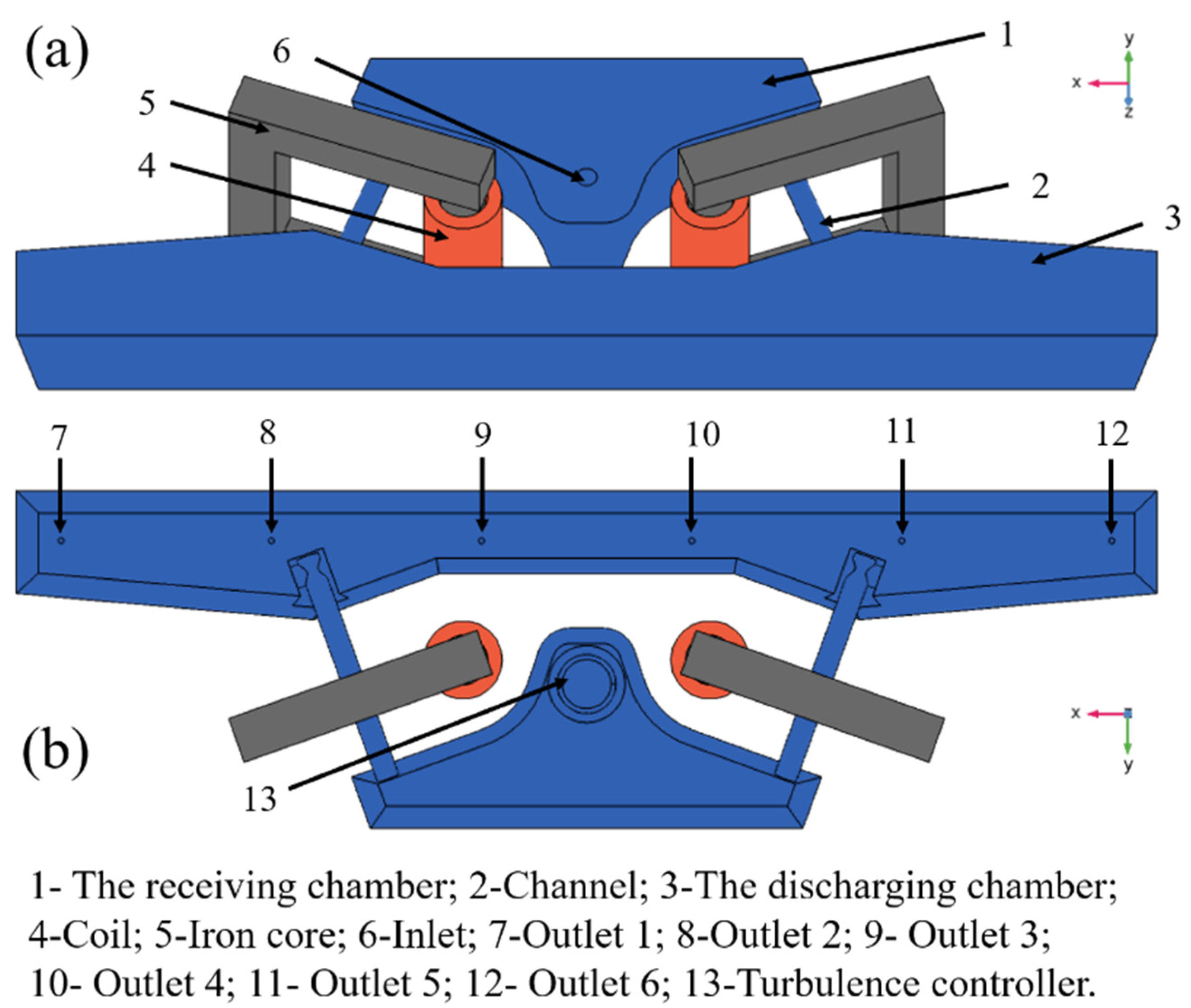
2.1. Physical Model
2.1.1. Geometry
2.1.2. Experimental Method
2.2. Mathematical Models
2.2.1. Model Assumptions and Control Equations
- Surface slag’s impact on flow is not taken into account;
- Molten steel is an incompressible fluid;
- The flow field is regarded as a stable flow field, and the inclusions are only affected by gravity, buoyancy, viscous resistance, and electromagnetic force;
- The collision growth of inclusions is ignored;
- If the inclusions contact the top slag, it means that they will be separated from the metal melt.
2.2.2. Boundary Conditions
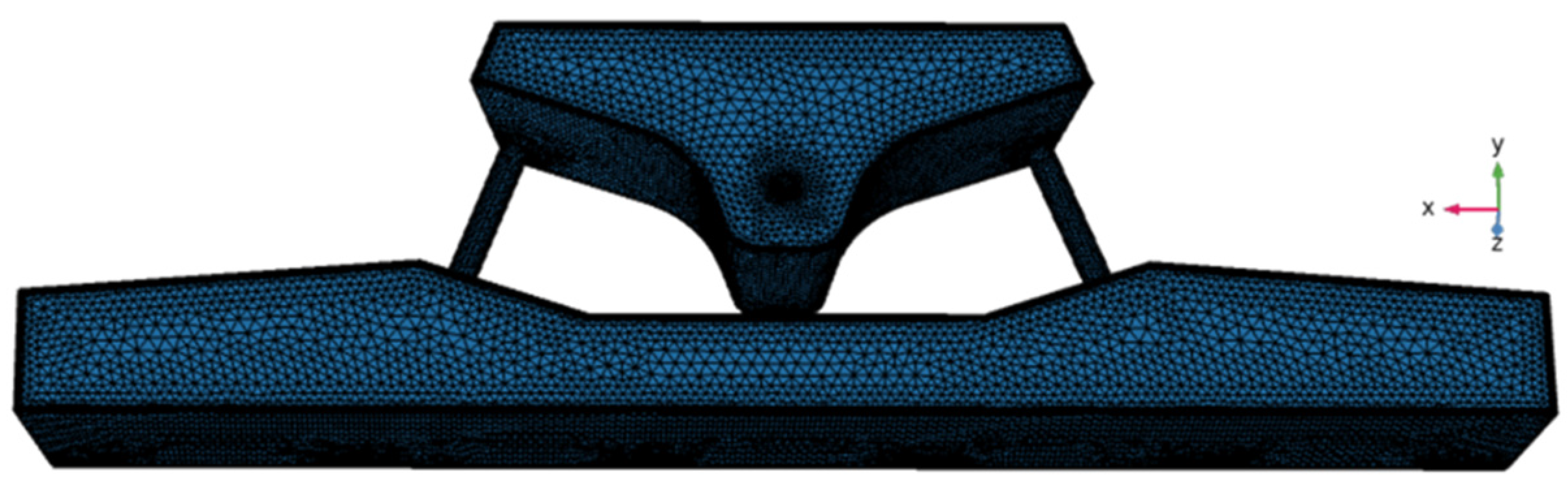
2.3. Mesh Independent Study
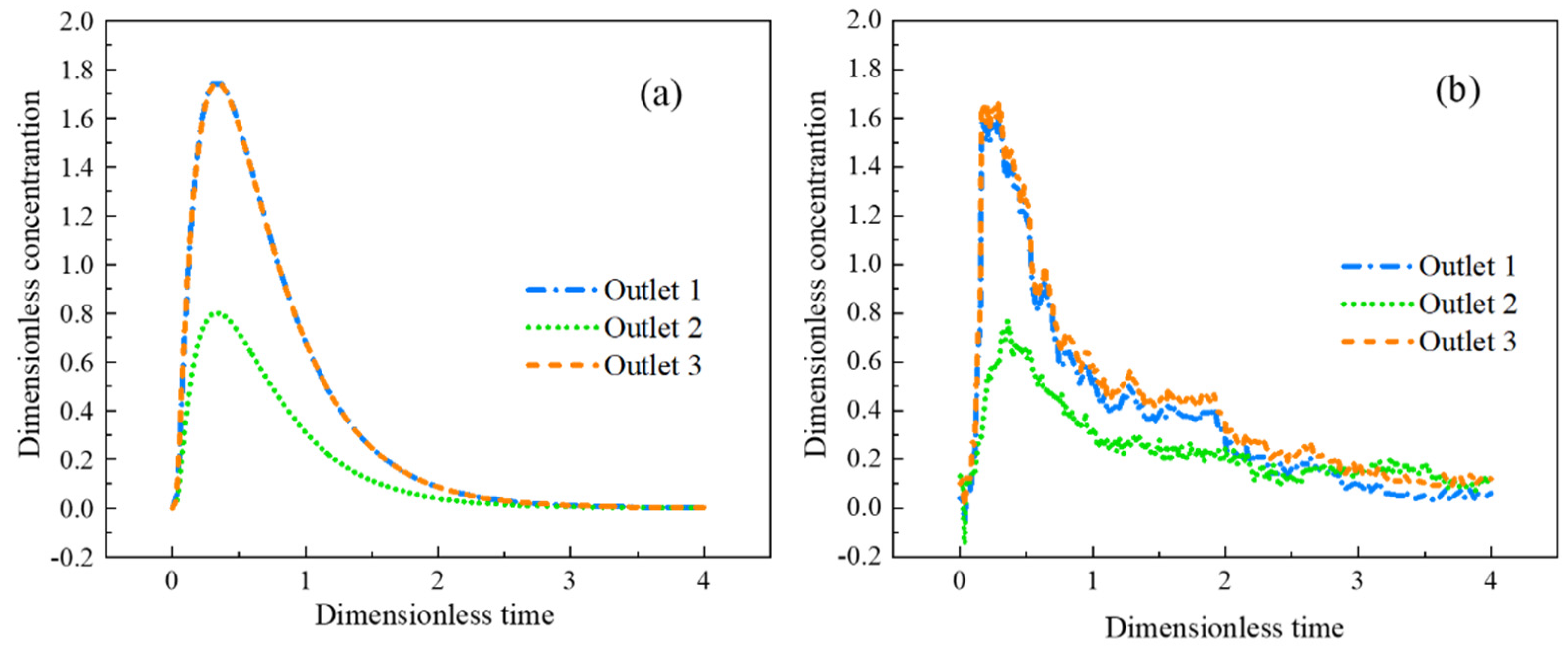
2.4. Model Validation
3. Results and Discussion
3.1. Physical Simulation Results
3.2. Mathematical Simulation Results
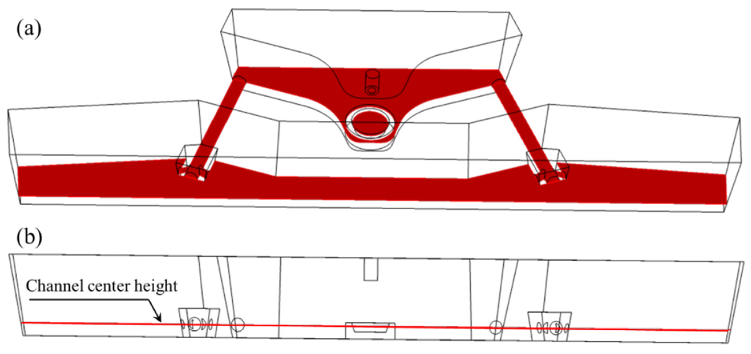
3.2.1. Simulation of the Temperature and Flow Fields
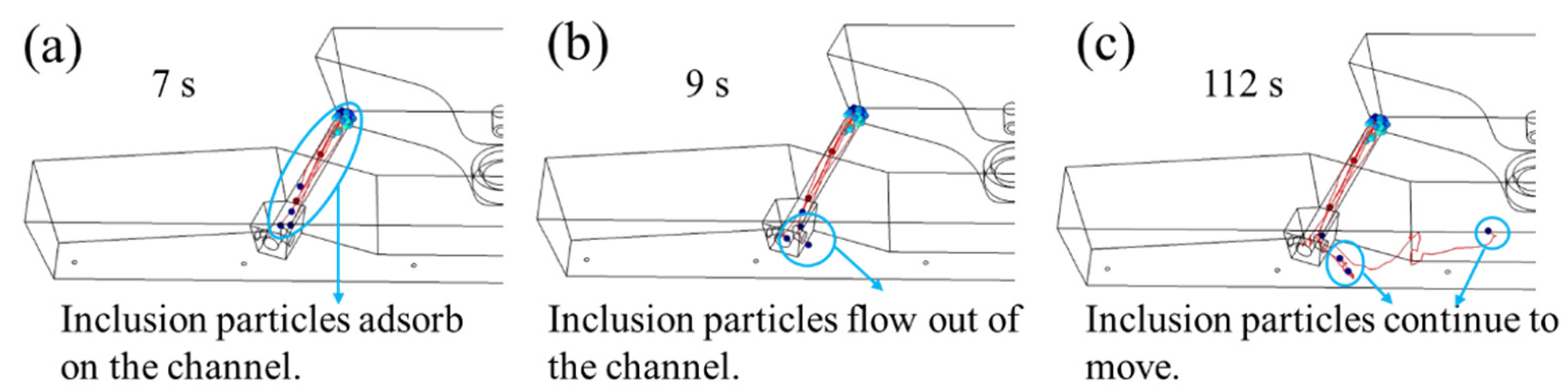
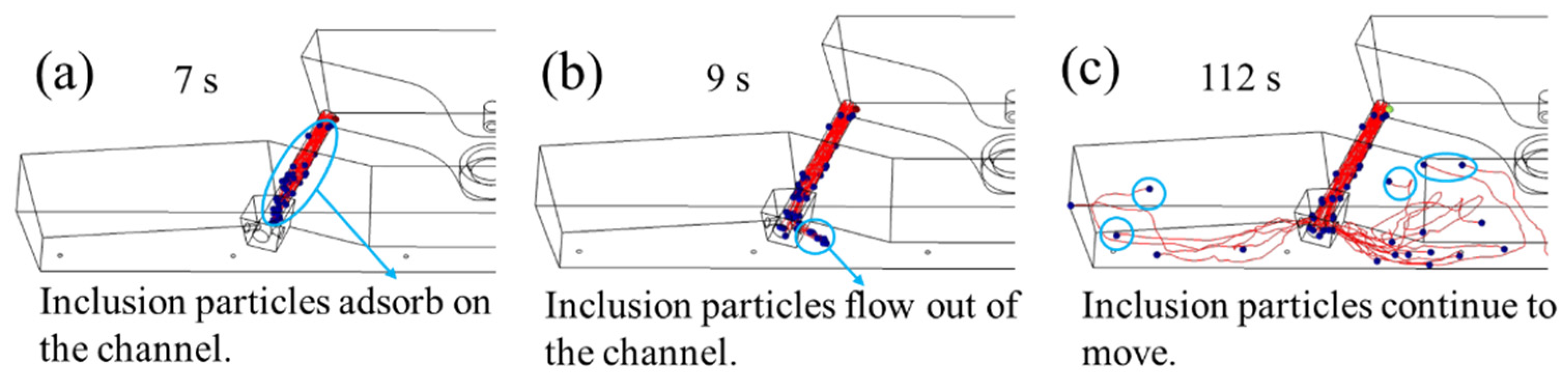
3.2.2. Simulation of Inclusion Removal from Tundish with and without Induction Heating
3.2.3. Simulation of Inclusion Removal with Various Sizes Using Induction Heating
4. Conclusions
- The mathematical simulation results of the removal of inclusions with and without induction heating show that the induction heating technology contributes to promoting the movement and removal of inclusions in the channel. Meanwhile, induction heating technology shortens inclusion particle removal time;
- Smaller inclusion particles are easier to be adsorbed in the channel, and larger inclusion particles are easier to be removed in the discharging chamber. The clearance rate of inclusion in the channel gradually decreases from 70.9% to 56.1%, with the diameter of inclusion particles increasing from 10 μm to 50 μm;
- The inclusion particles with large particle sizes are easier to be removed on the wall and liquid surface of the discharging chamber. Moreover, compared with small-size inclusions, the removal time of large-size inclusions is longer.
Author Contributions
Funding
Institutional Review Board Statement
Informed Consent Statement
Data Availability Statement
Acknowledgments
Conflicts of Interest
References
- Sahai, Y. Tundish technology for casting clean steel: A review. Metall. Mater. Trans. B 2016, 47, 2095–2106. [Google Scholar] [CrossRef]
- Jin, Y.; Dong, X.; Yang, F.; Cheng, C.; Li, Y.; Wang, W. Removal mechanism of microscale non-metallic inclusions in a tundish with multi-hole-double-baffles. Metals 2018, 8, 611. [Google Scholar] [CrossRef] [Green Version]
- Yang, Y.; Jönsson, P.G.; Ersson, M.; Nakajima, K. Inclusion Behavior under a Swirl Flow in a Submerged Entry Nozzle and Mold. Steel Res. Int. 2015, 86, 341–360. [Google Scholar] [CrossRef]
- Gildardo, S.D.; Rodolfo, D.M.; Jose de Jesus, B.S.; Hector Javier, V.H.; Angel, R.B.; Sergio, R.G. Numerical Modelling of Dissipation Phenomena in a New Ladle Shroud for Fluidynamic Control and Its Effect on Inclusions Removal in a Slab Tundish. Steel Res. Int. 2014, 85, 863–874. [Google Scholar]
- Zhang, L.F.; Taniguchi, S.; Cai, K.K. Fluid flow and inclusion removal in continuous casting tundish. Metall. Mater. Trans. B 2000, 31, 253–266. [Google Scholar] [CrossRef]
- Bao, Y.P.; Wang, M. Development trend of tundish metallurgical technology. Contin. Cast. 2021, 33, 2–11. [Google Scholar]
- Wang, Z.M.; Li, Y.; Wang, X.Z.; Li, X.L.; Yue, Q.; Xiao, H. Channel-Type Induction Heating Tundish Technology for Continuous Casting: A Review. Materials 2023, 16, 493. [Google Scholar] [CrossRef]
- Xing, F.; Zheng, S.G.; Zhu, M.Y. Motion and Removal of Inclusions in New Induction Heating Tundish. Steel Res. Int. 2018, 89, 1700542. [Google Scholar] [CrossRef]
- Yuan, C.; Liu, Y.; Li, G.Q.; Zhou, Y.S.; Huang, A. Interaction between microporous magnesia castable and 38CrMoAl steel. J. Iron Steel Res. Int. 2023, 30, 516–524. [Google Scholar] [CrossRef]
- Wang, P.; Xiao, H.; Chen, X.Q.; Li, X.S.; He, H.; Tang, H.Y.; Zhang, J.Q. Influence of Dual-Channel Induction Heating Coil Parameters on the Magnetic Field and Macroscopic Transport Behavior in T-Type Tundish. Metall. Mater. Trans. B. 2021, 52, 3447–3467. [Google Scholar] [CrossRef]
- Mabuchi, M.; Yoshii, Y.; Nozaki, T.; Kakiu, Y.; Kakihara, S.; Ueda, N. Investigation of the purification of molten steel by using tundish heater: Development on the controlling method of casting temperature in continuous casting V. ISIJ Int. 1984, 70, 118. [Google Scholar]
- Wang, Q.; Qi, F.S.; Li, B.K.; Tsukihashi, F. Behavior of Non-metallic Inclusions in a Continuous Casting Tundish with Channel Type Induction Heating. ISIJ Int. 2014, 54, 2796–2805. [Google Scholar] [CrossRef] [Green Version]
- Lei, H.; Yang, B.; Bi, Q.; Xiao, Y.Y.; Chen, S.F.; Ding, C.Y. Numerical Simulation of Collision-Coalescence and Removal of Inclusion in Tundish with Channel Type Induction Heating. ISIJ Int. 2019, 59, 1811–1819. [Google Scholar] [CrossRef] [Green Version]
- Miki, Y.; Thomas, B.G. Modeling of inclusion removal in a tundish. Metall. Mater. Trans. B 1999, 30, 639–654. [Google Scholar] [CrossRef]
- Xing, F.; Zheng, S.G.; Liu, Z.H.; Zhu, M.Y. Flow Field, Temperature Field, and Inclusion Removal in a New Induction Heating Tundish with Bent Channels. Metals 2019, 9, 561. [Google Scholar] [CrossRef] [Green Version]
- Zhang, Q.; Xu, G.Y.; Iwai, K. Effect of an AC Magnetic-field on the Dead-zone Range of Inclusions in the Circular Channel of an Induction-heating Tundish. ISIJ Int. 2022, 62, 56–63. [Google Scholar] [CrossRef]
- Yang, B.; Lei, H.; Bi, Q.; Jiang, J.M.; Zhang, H.W.; Zhao, Y.; Zhou, J.A. Electromagnetic Conditions in a Tundish with Channel Type Induction Heating. Steel Res. Int. 2018, 89, 1800145. [Google Scholar] [CrossRef]
- Yang, B.; Deng, A.Y.; Li, Y.; Wang, E.G. Exploration of the Relationship between the Electromagnetic Field and the Hydrodynamic Phenomenon in a Channel Type Induction Heating Tundish Using a Validated Model. ISIJ Int. 2022, 62, 677–688. [Google Scholar] [CrossRef]
- Yang, B.; Deng, A.Y.; Duan, P.F.; Kang, X.L.; Wang, E.G. “Power curve” key factor affecting metallurgical effects of an induction heating tundish. J. Iron Steel Res. Int. 2022, 29, 151–164. [Google Scholar] [CrossRef]
- Yue, Q.; Zhang, C.B.; Pei, X.H. Magnetohydrodynamic flows and heat transfer in a twin-channel induction heating tundish. Ironmak. Steelmak. 2017, 44, 227–236. [Google Scholar] [CrossRef]
- Chen, X.Q.; Xiao, H.; Wang, P.; Lan, P.; Tang, H.Y.; Zhang, J.Q. Effect of Channel Heights on the Flow Field, Temperature Field, and Inclusion Removal in a Channel-type Induction Heating Tundish. In 12th International Symposium on High-Temperature Metallurgical Processing; Springer International Publishing: Cham, Switzerland, 2022; pp. 501–522. [Google Scholar]
- Zhang, H.; Lei, H.; Ding, C.; Chen, S.; Niu, H.; Yang, B. Deep Insight into the Pinch Effect in a Tundish with Channel-Type Induction Heater. Steel Res. Int. 2022, 93, 2200181. [Google Scholar] [CrossRef]
- Launder, B.E.; Spalding, D.B. Numerical Prediction of Flow, Heat Transfer, Turbulence and Combustion, 1st ed.; Pergamon: Oxford, UK, 1983; pp. 96–116. [Google Scholar]
- Brenner, H.; Bielenberg, J.R. A continuum approach to phoretic motions: Thermophoresis. Phys. A 2005, 355, 251–273. [Google Scholar] [CrossRef]
- Bielenberg, J.R.; Brenner, H. A hydrodynamic/Brownian motion model of thermal diffusion in liquids. Phys. A 2005, 356, 279–293. [Google Scholar] [CrossRef]
- Vives, C.; Ricou, R. Magnetohydrodynamic flows in a channel-induction furnace. Metall. Mater. Trans. B. 1991, 22, 193–209. [Google Scholar] [CrossRef]


| Parameter | Value | Parameter | Value |
|---|---|---|---|
| Inlet velocity, m·s−1 | 0.9 | Thermal conductivity, W·m−1·K−1 | 23.5 |
| Inlet temperature, K | 1833 | Heat capacity at constant pressure, J·kg−1·K−1 | 4500 |
| The diameter of the particle, μm | 10, 30, 50 | Dynamic viscosity, Pa·s | 0.0065 |
| Particle density, kg·m−3 | 3900 | Surface heat loss, W·m−2 | 15,000 |
| Particle count released at a time | 1000 | Bottom heat loss, W·m−2 | 1800 |
| Particle precision order | 5 | Side heat loss, W·m−2 | 4600 |
| Molten steel density, kg·m−3 | 7580 | Channel heat loss, W·m−2 | 2000 |
| Number of Grids | 400,000 | 600,000 | 1,000,000 | 1,300,000 | 1,800,000 | 2,000,000 |
| Average velocity, m·s−1 | 0.0194 | 0.0198 | 0.0203 | 0.0209 | 0.0209 | 0.0209 |
| Outlet’s Number | 1 | 2 | 3 | 4 | 5 | 6 |
|---|---|---|---|---|---|---|
| Average temperature, K | 1860.3 | 1857.1 | 1862.3 | 1862.5 | 1857.0 | 1860.5 |
| Local Area in the Tundish | Removal Rate without Induction Heating, % | Removal Rate with Induction Heating, % |
|---|---|---|
| The receiving chamber | 97.500 | 96.400 |
| Channel | 2.100 | 3.000 |
| The wall of discharging chamber | 0.030 | 0.040 |
| Liquid level in discharging chamber | 0.000 | 0.000 |
| Outlet | 0.000 | 0.010 |
Disclaimer/Publisher’s Note: The statements, opinions and data contained in all publications are solely those of the individual author(s) and contributor(s) and not of MDPI and/or the editor(s). MDPI and/or the editor(s) disclaim responsibility for any injury to people or property resulting from any ideas, methods, instructions or products referred to in the content. |
© 2023 by the authors. Licensee MDPI, Basel, Switzerland. This article is an open access article distributed under the terms and conditions of the Creative Commons Attribution (CC BY) license (https://creativecommons.org/licenses/by/4.0/).
Share and Cite
Yi, B.; Zhang, G.; Jiang, Q.; Zhang, P.; Feng, Z.; Tian, N. The Removal of Inclusions with Different Diameters in Tundish by Channel Induction Heating: A Numerical Simulation Study. Materials 2023, 16, 5254. https://doi.org/10.3390/ma16155254
Yi B, Zhang G, Jiang Q, Zhang P, Feng Z, Tian N. The Removal of Inclusions with Different Diameters in Tundish by Channel Induction Heating: A Numerical Simulation Study. Materials. 2023; 16(15):5254. https://doi.org/10.3390/ma16155254
Chicago/Turabian StyleYi, Bing, Guifang Zhang, Qi Jiang, Peipei Zhang, Zhenhua Feng, and Nan Tian. 2023. "The Removal of Inclusions with Different Diameters in Tundish by Channel Induction Heating: A Numerical Simulation Study" Materials 16, no. 15: 5254. https://doi.org/10.3390/ma16155254