
Operational and Material Causes of High-Pressure Turbine Disc Damage in the RD-33 Engine


Abstract
:1. Introduction
2. Test Results and Discussion
2.1. Structural and Strength Analysis
2.2. Analysis of the Engine Operating Parameters
3. Summary and Conclusions
Author Contributions
Funding
Institutional Review Board Statement
Informed Consent Statement
Data Availability Statement
Conflicts of Interest
References
- Trelka, M.; Bartoszewicz, J.; Urbaniak, R. Selected problems of RD-33 engine reliability in operation. Combust. Engines 2016, 165, 33–40. [Google Scholar] [CrossRef]
- Szczepankowski, A.; Przysowa, R. Thermal degradation of turbine components in a military turbofan. Eng. Fail. Anal. 2022, 134, 106088. [Google Scholar] [CrossRef]
- Čerňan, J.; Janovec, M.; Hocko, M.; Cúttová, M. Damages of RD-33 Engine Gas Turbine and their Causes. Transp. Res. Procedia 2018, 35, 200–208. [Google Scholar] [CrossRef]
- Hocko, M. Gas corrosion of parts of turbofan military engine gas turbine. In Proceedings of the Thermophysical Basis of Energy Technologies (TBET 2020), Pilsen, Czech Republic, 8–10 September 2020. [Google Scholar] [CrossRef]
- Witek, L. Stress Analysis of Turbine Components under Spin Rig Thermomechanical Condition. Aviation 2004, 8, 21–26. [Google Scholar] [CrossRef]
- Čerňan, J.; Semrád, K.; Draganová, K.; Cúttová, M. Fatigue stress analysis of the DV-2 engine turbine disk. Aircr. Eng. Aerosp. Technol. 2019, 91, 708–716. [Google Scholar] [CrossRef]
- Hutiu, G.; Duma, V.-F.; Demian, D.; Bradu, A.; Podoleanu, A.G. Assessment of Ductile, Brittle, and Fatigue Fractures of Metals Using Optical Coherence Tomography. Metals 2018, 8, 117. [Google Scholar] [CrossRef]
- Takahashi, S.; Nishikiori, S.; Hosoya, M.; Arai, M.; Takekawa, M.; Tahara, K. Development of turbine disk materials for aircraft engines. In Proceedings of the International Gas Turbine Congress, Tokyo, Japan, 2–7 November 2003. IGTC2003Tokyo TS-127. [Google Scholar]
- Zhu, S.P.; Huang, H.Z.; He, L.P.; Liu, Y.; Wang, Z. A generalized energy-based fatigue–creep damage parameter for lifeprediction of turbine disk alloys. Eng. Fract. Mech. 2012, 90, 89–100. [Google Scholar] [CrossRef]
- Kumar, R.; Ranjan, V.; Kumar, B.; Ghoshal, S.K. Finite element modelling and analysis of the burst margin of a gas turbine disc using an area weighted mean hoop stress method. Eng. Fail. Anal. 2018, 90, 425–433. [Google Scholar] [CrossRef]
- Jiang, R.; Everitt, S.; Gao, N.; Soady, K.; Brooks, J.W.; Reed, P.A. Influence of oxidation on fatigue crack initiation and propagation in turbine disc alloy N18. Int. J. Fatigue 2015, 75, 89–99. [Google Scholar] [CrossRef]
- Radavich, J.; Furrer, D.; Carneiro, T.; Lemsky, J. The Microstructure and Mechanical Properties of EP741NP Powder Metallurgy Disc Material. Superalloys 2008. Available online: https://www.tms.org/superalloys/10.7449/2008/Superalloys_2008_63_72.pdf (accessed on 20 August 2023).
- Sentyurina, Z.A.; Baskov, F.A.; Loginov, P.A.; Kaplanskii, Y.Y.; Mishukov, A.V.; Logachev, I.A.; Bychkova, M.Y.; Levashov, E.A.; Logacheva, A.I. The effect of hot isostatic pressing and heat treatment on the microstructure and properties of EP741NP nickel alloy manufactured by laser powder bed fusion. Addit. Manuf. 2021, 37, 101629. [Google Scholar] [CrossRef]
- Baskov, F.A.; Sentyurina, Z.A.; Kaplanskii, Y.Y.; Logachev, I.A.; Semerich, A.S.; Levashov, E.A. The influence of post heat treatments on the evolution of microstructure and mechanical properties of EP741NP nickel alloy produced by laser powder bed fusion. Mater. Sci. Eng. A 2021, 817, 141340. [Google Scholar] [CrossRef]
- Jiang, R.; Song, Y.D.; Reed, P.A. Fatigue crack growth mechanisms in powder metallurgy Ni-based superalloys—A review. Int. J. Fatigue 2020, 141, 105887. [Google Scholar] [CrossRef]
- Volkov, A.M.; Vostrikov, A.V.; Bakradze, M.M. Principles of Creation and Features of Alloying Granulated Heat-Resistant Nickel Alloys. Proc. VIAM 2016, 8, 8–14. [Google Scholar] [CrossRef]
- Lomberg, B.S.; Baburina, E.V.; Nikolskaya, V.N. Influence of Long-Term High-Temperature Heating on the Structure and Mechanical Properties of EP741P Powder Alloy; Aviation Materials; VIAM: Moscow, Russia, 1982; Volume 1, pp. 27–34. [Google Scholar]
- Gerasimova, L.P.; Godovanets, M.A.; Kotov, V.F.; Popova, L.E.; Shvarts, V.I. Plastic strain and fracture behavior of ep 741 nickel alloys under conditions of high temperature deformation. Poroshkovaya Metall. 1984, 257, 51–57. [Google Scholar]
- Ezhov, A.A.; Shvarts, V.I.; Popova, L.E.; Gerasimova, L.P.; Davydova, V.A.; Kotov, V.F.; Eremenko, V.I. Investigation of the fracture behavior of EP-741P heat-resisting alloy by thermal microscopy. Poroshkovaya Metall. 1981, 222, 54–59. [Google Scholar]
- John, R.; Tadeu, C.; David, F.; Joseph, L.; Anthony, B. Effect of Processing and Composition on the Structure and Properties of P/M EP741NP Type Alloys. Chin. J. Aeronaut. 2007, 20, 97–106. [Google Scholar] [CrossRef]
- Hou, J.S.; Guo, J.T.; Wu, Y.X.; Zhou, L.Z.; Ye, H.Q. Effect of hafnium on creep behavior of a corrosion resistant nickel base superalloy. Mater. Sci. Eng. A 2010, 527, 1548–1554. [Google Scholar] [CrossRef]
- Trunkin, I.N.; Artamonov, M.A. Investigation of Hafnium-Containing Defects In EP741NP Granulated Nickel Alloy, Used for Manufacturing of Aircraft Engine Discs. Bull. Samara Univ. Aerosp. Eng. Technol. Eng. 2019, 18, 89–95. [Google Scholar] [CrossRef]
- PN-EN ISO 6892-1:2020-05; Metals—Tensile Test—Part 1: Room Temperature Test Method. Polish Committee for Standardization: Warsaw, Poland, 2020.
- Bakradze, M.M.; Lomberg, B.S.; Sidorov, S.A.; Bubnov, M.B. Manufacturing of Large-scale Forgings of Disc GTE from Industrial Industry d 320 mm Alloy EK151-ID. Trydy VIAM 2017, 6, 11–19. [Google Scholar] [CrossRef]
- PN 64/H-04510:1964; Determination of Content of Non-Metallic Inclusion in Steel. Polish Committee for Standardization: Warsaw, Poland, 2013.


| Sample Specification | Thickness [c] [mm] | Width [mm] | Yield Strength Rp0.2 [MPa] | Tensile Strength Rm [MPa] | Elongation A [%] |
|---|---|---|---|---|---|
| 1-1 | 2.43 | 4.14 | 896 | 1391 | 19.5 |
| 1-2 | 2.47 | 4.14 | 894 | 1371 | 19.6 |
| 1-3 | 2.44 | 4.13 | 894 | 1398 | 23.5 |
| 2-1 | 2.43 | 4.12 | 907 | 1421 | 23.4 |
| 2-2 | 2.45 | 4.12 | 908 | 1419 | 25.6 |
| 2-3 | 2.43 | 4.12 | 908 | 1413 | 23.4 |
| 3-1 | 2.45 | 4.12 | 911 | 1423 | 23.8 |
| 3-2 | 2.46 | 4.12 | 910 | 1306 | 15.9 |
| 3-3 | 2.45 | 4.12 | 919 | 1397 | 21.3 |
| 4-1 | 2.41 | 4.12 | 911 | 1423 | 20.4 |
| 4-2 | 2.40 | 4.13 | 917 | 1392 | 20.0 |
| 4-3 | 2.43 | 4.12 | 916 | 1396 | 20.3 |
| 5-1 | 1.76 | 4.12 | 905 | 1391 | 19.7 |
| 5-2 | 1.75 | 4.12 | 911 | 1400 | 18.0 |
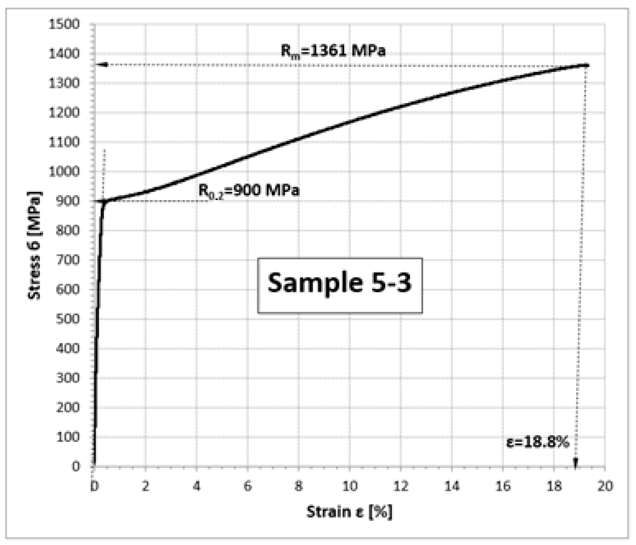
| 5-3 | 1.76 | 4.12 | 900 | 1361 | 18.8 |
| Distance from the Disc Foot Plate [mm] | Rp0.2 [MPa] | Rm [MPa] | A [%] |
|---|---|---|---|
| 23 (area 1) | 894.7 ± 0.9 | 1386.7 ± 11.4 | 20.9 ± 1.9 |
| 63 (area 2) | 907.7 ± 0.5 | 1417.7 ± 3.4 | 24.1 ± 1.0 |
| 85 (area 3) | 913.3 ± 4.0 | 1375.3 ± 50.2 | 20.3 ± 3.3 |
| 128 (area 4) | 914.7 ± 2.6 | 1403.7 ± 13.8 | 20.2 ± 0.2 |
| 175 (area 5) | 905.3 ± 4.5 | 1384.0 ± 16.7 | 18.8 ± 0.7 |
| Parameter | Tested Disc Material | EP741NP Generation 1981 [16] | EP741NP Generation 1995 [16] | EP741NP [24] | |
|---|---|---|---|---|---|
| Rm [MPa] | r = 23 | 1387 | 1355 | 1420 | 1560 |
| r = 63 | 1418 | ||||
| r = 85 | 1375 | ||||
| r = 128 | 1403 | ||||
| r = 175 | 1384 | ||||
| R0.2 [MPa] | r = 23 | 895 | 885 | 1025 | 1020 |
| r = 63 | 908 | ||||
| r = 85 | 913 | ||||
| r = 128 | 915 | ||||
| r = 175 | 905 | ||||
| A[%] | r = 23 | 21 | 17 | 20 | 19 |
| r = 63 | 24 | ||||
| r = 85 | 20 | ||||
| r = 128 | 20 | ||||
| r = 175 | 19 | ||||
Disclaimer/Publisher’s Note: The statements, opinions and data contained in all publications are solely those of the individual author(s) and contributor(s) and not of MDPI and/or the editor(s). MDPI and/or the editor(s) disclaim responsibility for any injury to people or property resulting from any ideas, methods, instructions or products referred to in the content. |
© 2023 by the authors. Licensee MDPI, Basel, Switzerland. This article is an open access article distributed under the terms and conditions of the Creative Commons Attribution (CC BY) license (https://creativecommons.org/licenses/by/4.0/).
Share and Cite
Jóźwiak, S.; Kozakiewicz, A.; Kachel, S.; Zasada, D. Operational and Material Causes of High-Pressure Turbine Disc Damage in the RD-33 Engine. Materials 2023, 16, 5939. https://doi.org/10.3390/ma16175939
Jóźwiak S, Kozakiewicz A, Kachel S, Zasada D. Operational and Material Causes of High-Pressure Turbine Disc Damage in the RD-33 Engine. Materials. 2023; 16(17):5939. https://doi.org/10.3390/ma16175939
Chicago/Turabian StyleJóźwiak, Stanisław, Adam Kozakiewicz, Stanisław Kachel, and Dariusz Zasada. 2023. "Operational and Material Causes of High-Pressure Turbine Disc Damage in the RD-33 Engine" Materials 16, no. 17: 5939. https://doi.org/10.3390/ma16175939
APA StyleJóźwiak, S., Kozakiewicz, A., Kachel, S., & Zasada, D. (2023). Operational and Material Causes of High-Pressure Turbine Disc Damage in the RD-33 Engine. Materials, 16(17), 5939. https://doi.org/10.3390/ma16175939