Article

Enhancing the SCC Resistance of the Anchor Steel with Microalloying in a Simulated Mine Environment

1
School of Civil and Resource Engineering, University of Science and Technology Beijing, Beijing 100083, China
2
Technology Research Institute of Shanxi Jincheng Coal Group Co., Ltd., Jincheng 048000, China
3
National Materials Corrosion and Protection Scientific Data Center, Key Laboratory for Corrosion and Protection (MOE), University of Science and Technology Beijing, Beijing 100083, China
4
School of Energy and Mining Engineering, China University of Mining and Technology-Beijing, Beijing 100083, China
5
Hebei Special Equipment Supervision and Inspection Institute, Key Laboratory of Safety Evaluation of Steel Pipes and Fittings for State Market Regulation, Shijiazhuang 050061, China
*
Authors to whom correspondence should be addressed.
Materials 2023, 16(17), 5965; https://doi.org/10.3390/ma16175965
Submission received: 1 August 2023 / Revised: 25 August 2023 / Accepted: 29 August 2023 / Published: 31 August 2023
(This article belongs to the Topic Alloys and Composites Corrosion and Mechanical Properties)

Abstract

:
This work explored a new idea for enhancing the resistance to stress corrosion cracking (SCC) of mining anchor steel through microalloying. Microalloyed anchor steels with Nb, Cu, Ni, Sb, and C were prepared through vacuum smelting and hot rolling. Electrochemical measurements, slow strain rate tensile (SSRT) tests, and fracture morphology observations were used to study the electrochemical and SCC behavior in the simulated mine environment. The results proved that the microstructure of microalloyed steels varies slightly. Adding Ni, Cu, and Sb can improve the mechanical properties of the anchor steel, while reducing C content decreases tensile strength as a result of loss of the solution-strengthening effect. The addition of Sb, Cu, Ni, and reducing the content of C enhances the resistance to corrosion and SCC by mitigating anodic dissolution (AD), while adding Nb improves SCC resistance by inhibiting hydrogen embrittlement (HE). The combined addition of 1% Ni, 0.5% Cu, 0.05% Nb, 0.1% Sb, and 0.5% C presented the highest SCC resistance, which is a promising prospect for the development of high-performance, low-alloy anchor steels. The combined addition of 1% Ni, 0.5% Cu, 0.05% Nb, and 0.1% Sb resulted in the inhibition of electrochemical reactions and corrosion. As a result of the synergistic effect of the microalloy, both AD and HE mechanisms were simultaneously inhibited, which greatly enhanced SCC resistance.

1. Introduction

Anchoring technology has been widely used in all types of mines, but the service conditions of the anchor cables and rods have been deteriorating year by year due to the increasing mining depth and corrosion problems in various aggressive mine environments. According to reported statistics [1,2], 29% of anchor bolts and 25% of anchor cables in the Australian mining industries are subjected to corrosion failures, and corrosion has been recognized as one of the biggest threats to the life of anchor bolt structures buried in rock and soil layers. In addition, at external load or residual stress, stress corrosion cracking (SCC) and hydrogen embrittlement (HE) happen frequently and lead to abrupt failures [3,4,5]. Therefore, SCC and HE problems pose a serious threat to the safe service of anchor bolt structures and severely affect the development and application of anchor steels.
Studies have shown that high-strength anchor steels are vulnerable to SCC in chloride-containing environments [6,7]. The SCC mechanism is considered a mixture of anodic dissolution (AD) and hydrogen embrittlement (HE). Microalloying has become the mainstream method for optimizing corrosion and SCC resistance by inhibiting AD and HE. It has been reported that Ni, Nb, Cu, Sb, and C have a great impact on corrosion and SCC. In general, Ni, Cu, and Sb can mitigate AD, while adding Nb prevents HE. It has been reported that Ni can greatly enhance the corrosion resistance of steels by improving the compactness of the rust layer [8,9]. Adding Cu can improve corrosion resistance because it facilitates CuO formation and enhances the protective capacity of the corrosion product layer [8]. In addition, in Ni-bearing steels, a small amount of Cu addition can be beneficial to the function of Ni in improving the rust layer protectiveness [10]. Sb is an acid-resistant element and has a synergetic effect with Cu and Ni, which can inhibit AD and improve corrosion resistance [11]. Previous work has proved that Sb induces the enrichment of Cu and Ni and improves the resistance of the rust layer to corrosive chloride ions [11]. Therefore, the combined addition of Ni, Cu, and Sb should be effective at improving the SCC resistance of anchor steels by mitigating AD. Nb can mitigate hydrogen-induced cracking problems by inhibiting crack initiation and propagation [12] because Nb addition can facilitate the formation of nanoprecipitated Nb(C, N), which can act as hydrogen traps and prevent hydrogen diffusion [13]. Adding C can refine grains and improve the strength of steels by the solution-strengthening mechanism but has an opposite effect on corrosion behavior. C addition can facilitate carbide formation at grain boundaries and cause intergranular corrosion [14]. Hence, the addition of Nb and adjusting the content of C are also expected to enhance the resistance to corrosion and SCC. The above research has demonstrated that microalloying is feasible in mitigating the SCC of low-alloy steels. However, few studies have paid attention to the microalloy effect on the SCC behavior and mechanism of anchor steels.
Therefore, based on the above progress, in this work, a series of anchor cable steels were prepared by adding Nb, Sb, Cu, Ni, and reducing C content. The effect of microalloying on the SCC behavior and mechanism was analyzed systematically, which is anticipated to propose new ideas and theoretical support for the application and safe service of anchor steels.

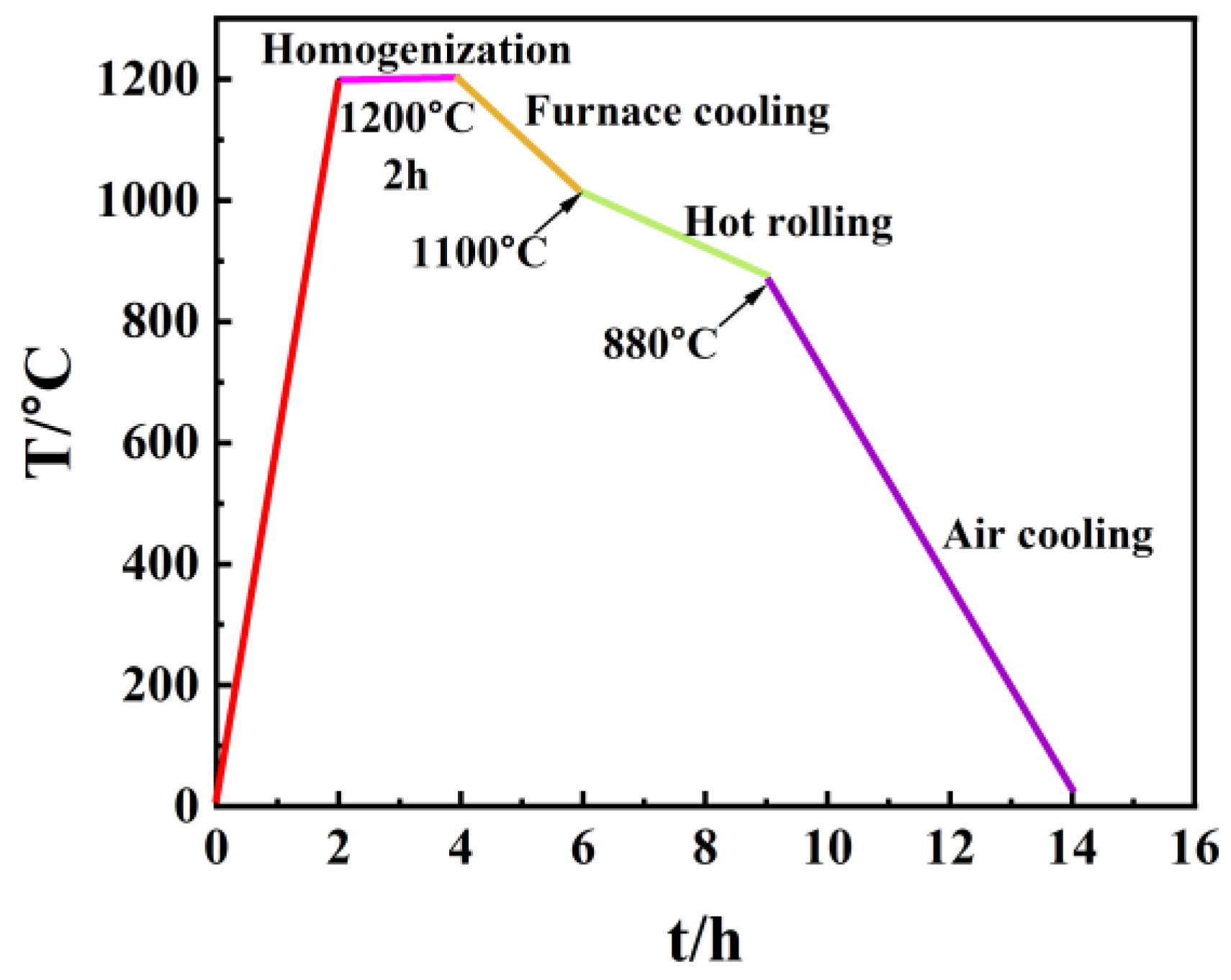
2. Experimental Procedures

2.1. Materials and Solution

Four types of low-alloy, ultra-high-strength anchor steels with different chemical compositions were prepared, and the chemical composition is listed in Table 1. Commercial YL82B steel was selected as the as-received material, which is labeled as the BM in this work. Three other kinds of steels were added to alloy elements compared to the BM. 0.5NiCu denotes the addition of 0.5% Ni with 0.5% Cu and other trace alloying elements (0.046% Nb + 0.11% Sb). 1NiCu represents the adjustment of Ni elements to 1% and the decrease in carbon content to 0.53% compared to 0.5NiCu. LNiCu represents the decrease in carbon content to 0.34% in comparison to 1NiCu as the decarburized version of 1NiCu. The ingots were prepared by vacuum smelting in a vacuum induction furnace, and the procedures are illustrated in Figure 1. As shown, the ingots were homogenized at 1200 °C for 2 h, furnace-cooled at 1010 °C, and then hot-rolled at the final temperature of 880 °C followed by air cooling. All the test specimens in this work were taken from the center thickness of the steel sheet to avoid the possible errors caused by surface decarburization during hot rolling.
The corrosive medium in this work was the simulated mine environment, and the chemical composition is shown in Table 2 according to the analysis of the chemical composition of the groundwater and soluble gas contents in underground coal mines. The solution pH was adjusted to 5.0 with acetic acid. All the ingredients were analytically pure for the preparation of the simulated solution, and all the tests were performed at ambient temperature.

2.2. Microstructural Analysis

Metallographic samples with size of 10 mm × 10 mm × 3 mm were cut from the rolling and transverse (RD–TD) planes. Then, all samples were ground to 3000 grits with SiC paper, mechanically polished to 1 μm, and chemically etched with 4% nital solution. The microstructure was observed with an FEI Quanta 250 scanning electron microscope (Eindhoven, The Netherlands) (SEM).

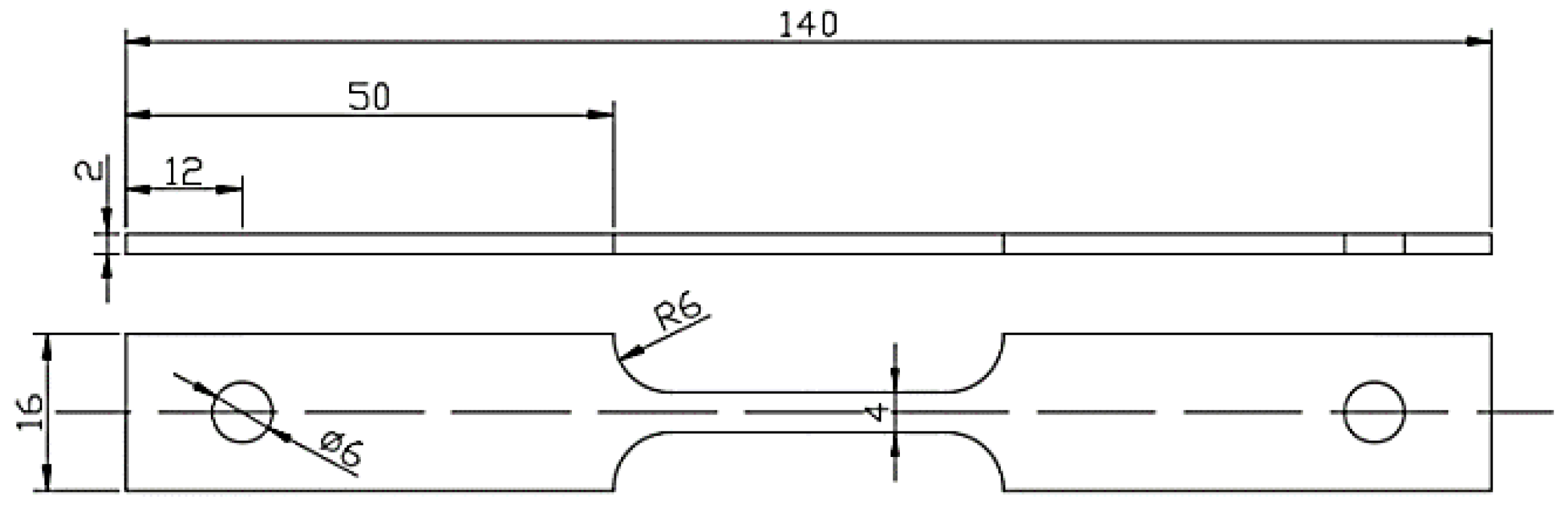
2.3. Mechanical Property Test

Tensile tests were carried out to study the mechanical properties of the test steels. The test specimens were cut from the rolling–transverse (TD–RD) plane along the rolling direction, and the dimensions are shown in Figure 2 in accordance with the Chinese National Standard GB/T228.1-2021 [15]. Prior to the test, the gauge length of the specimens was sequentially ground with SiC paper to 3000#, and the final grinding direction was parallel to the gauge length. The tensile tests were performed with an MTS-Landmark-730 hydraulic servo fatigue testing machine (Eden Prairie, MN, USA) with the tensile rate of 10−3 s−1. After fracture, the elongation and cross-sectional area were measured with a vernier caliper. All the tests were performed at least three times to ensure the repeatability and reliability of the results.

2.4. Electrochemical Measurements

The electrochemical properties of the test steels were measured with a VersaSTAT3 electrochemical workstation produced by Princeton Applied Research (Trenton, NJ, USA). The three-electrode system was applied, in which the saturated calomel electrode (SCE) was used as the reference electrode, a platinum plate as the counter electrode, and the test steel with the dimension of 10 mm × 10 mm × 3 mm as the working electrode. The test specimens were sealed with epoxy resin except for the 1 cm2 working area, and the working surface was ground with SiC paper sequentially to 3000 grits and washed with deionized water and alcohol, followed by blow drying. Prior to the test, the air-formed oxide film was removed through potentiostatic polarization at −1.2 V (vs. SCE) for 60 s, and then the open-circuit potential (OCP) was recorded for at least 30 min until reaching a steady state. The electrochemical impedance spectroscopy (EIS) measurements were performed at the AC excitation amplitude of 10 mV and the test frequency ranging from 100 kHz to 10 mHz. Potentiodynamic polarization measurements were conducted at the scan range of −1.2 V to −0.4 V (vs. SCE), and two scan rates were chosen: 0.5 mV/s to study the quasi-steady electrochemical process at the crack wall and 200 mV/s to study the non-steady electrochemical process at the crack tip [16]. All experiments were repeated more than three times in order to ensure repeatability and accuracy.

2.5. SSRT Tests

Slow strain rate tensile (SSRT) tests were performed to study the SCC susceptibility of the test steels. The dimension and the preparation of test specimens were the same as procedures described in Section 2.2. The SSRT tests were carried out at a strain rate of 10−6 s−1 with a WDML-30 kN material testing system. Each type of test steel was tested in air, under OCP and −1200 mV (vs. SCE) to study the SCC in the test solution without/with hydrogen charging. Prior to the test, specimens were preloaded with approximately 500 N for 12 h in the test solution in order to make sure that a uniform electrolyte film formed. For specimens tested at −1200 mV, potentiostatic polarization was imposed before and throughout the test. To ensure repeatability, all tests were performed at least three times. The elongation loss (Iσ) and the loss of the reduction in area (IΨ) were calculated with Equations (1) and (2) for characterizing the SCC susceptibility.
I σ = 1 δ s δ 0 × 100 %
I ψ = 1 ψ s ψ 0 × 100 %
where δs and δ0 are the elongation rates of specimens tested in solution and air, respectively; Ψs and Ψ0 are the reductions in area of the specimens tested in solution and air, respectively. However, the strengths of the four kinds of test steels are different, which makes the above equations fail to characterize the real SCC susceptibility differences among the different test steels. For example, under the same external stress, when the steel with a lower yield strength passes the yield point, the steel with a higher yield strength is below the yield point. This causes the steel with the higher yield strength to present lower Iσ and IΨ values than that with the lower yield strength. Therefore, we used the normalized elongation loss (Iσx) and the normalized loss of the reduction in area (IΨx) to evaluate SCC susceptibility, and the formulas for calculating them are as shown in (3) and (4):
I σ x = I σ σ s x / σ s 0   ( x = 1 , 2 , 3 )
I Ψ x = I Ψ σ s x / σ s 0   ( x = 1 , 2 , 3 )
where σsx (x = 1, 2, 3) is the yield strength of the 0.5NiCu, 1NiCu, and LNiCu anchor steel; σs0 is the yield strength of the BM.
After the SSRT tests, the fracture surface was cut for the morphology observation, and then the corrosion products were removed by ultrasonic cleaning in the mixed solution of 500 mL HCl + 500 mL H2O + 5 g hexamethylenetetramine for about 4~8 s. The fracture surface morphology and secondary cracks were observed with an FEI Quanta 250 SEM.

3. Results

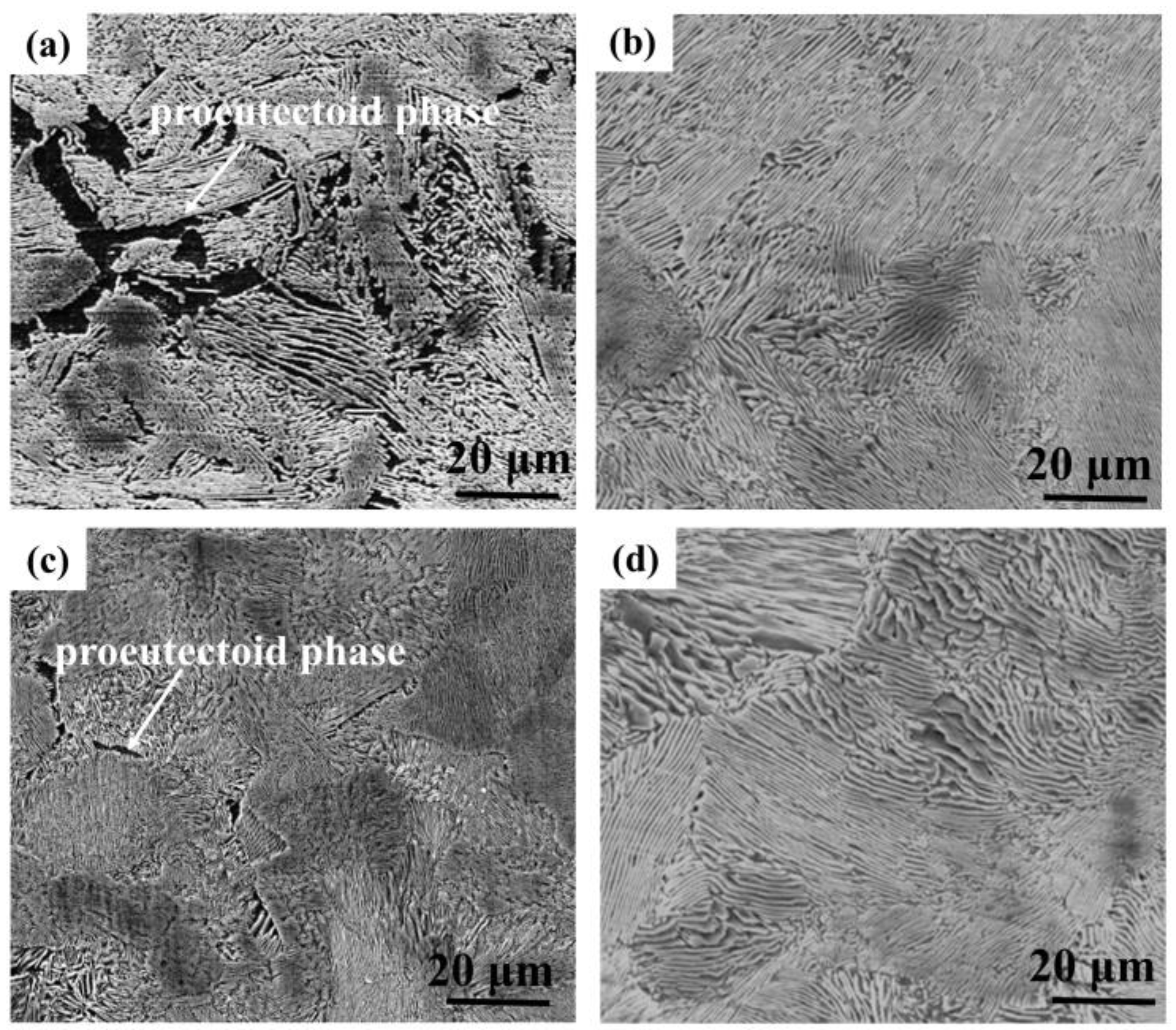
3.1. Microstructural Characterization

The microstructure of the test steels is shown in Figure 3. The microstructure of the four kinds of anchor bolt steels is mainly composed of pearlite, which appears as a fine lamellar structure. A small amount proeutectoid phase also exists and is inhomogeneously distributed as a result of the proeutectoid phase transformation, which is common in hypoeutectoid steels [17,18]. The results indicated that microalloying and decarburization (as represented by LNiCu) had no obvious influence on the steel microstructure.

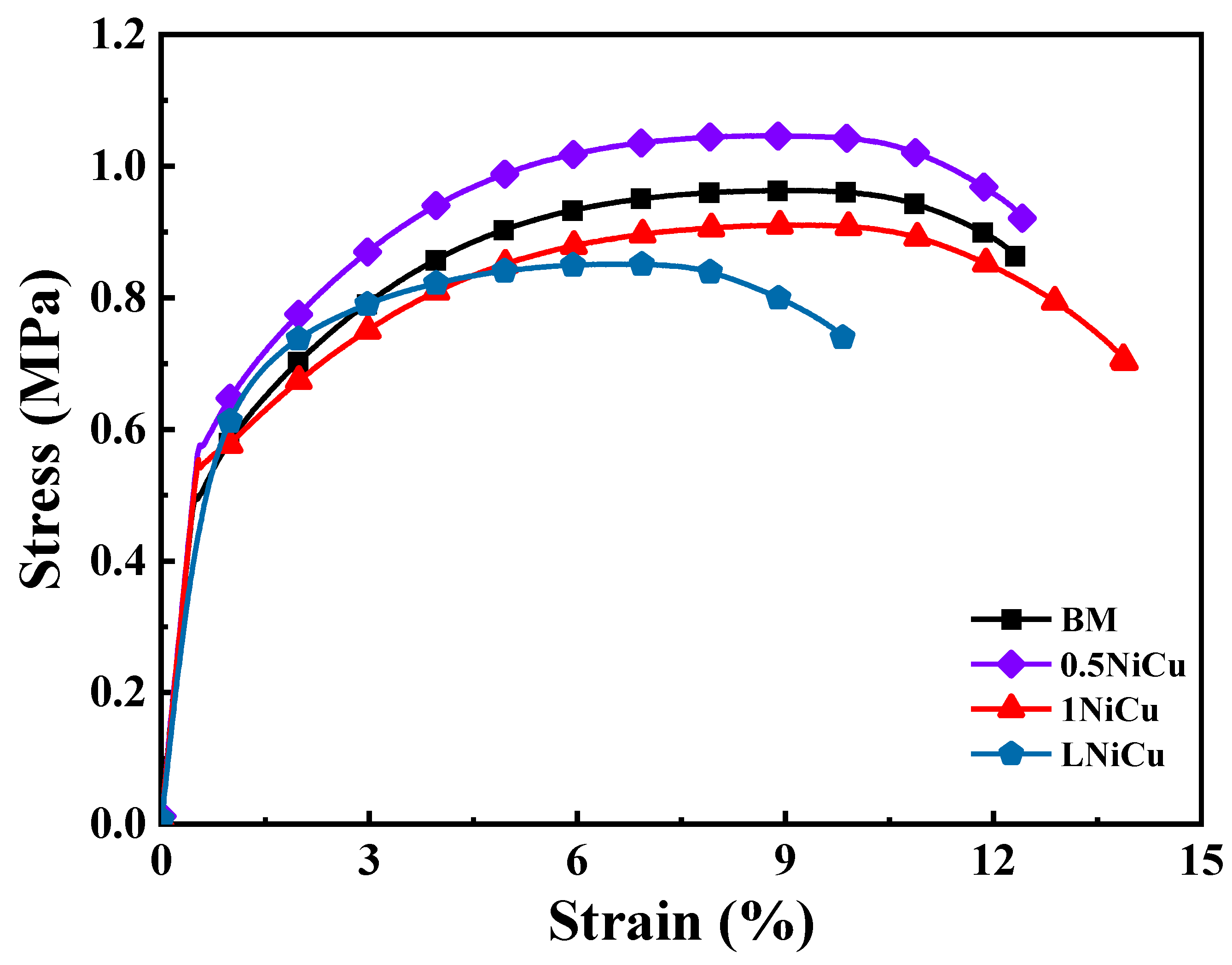
3.2. Mechanical Properties

Stress–strain curves for the four test steels are shown in Figure 4, and the mechanical properties are listed in Table 3. The tensile strength of 0.5NiCu is the highest (1046 MPa), while the elongation decreases slightly compared to the BM. Due to the addition of the alloying elements Cu, Nb, Ni, and Sb, the microalloyed anchor steels present a higher yield ratio. The tensile strength of the 1NiCu and LNiCu is slightly lower than that of the BM, and the tensile strength of the LNiCu is the lowest due to the loss of the solution-strengthening effect as a result of the decreased C content [19]. Therefore, decarburization causes a decrease in the tensile strength. The mechanical properties of the various designed microalloyed steels satisfy the basic requirements compared to the BM.

3.3. Electrochemical Properties
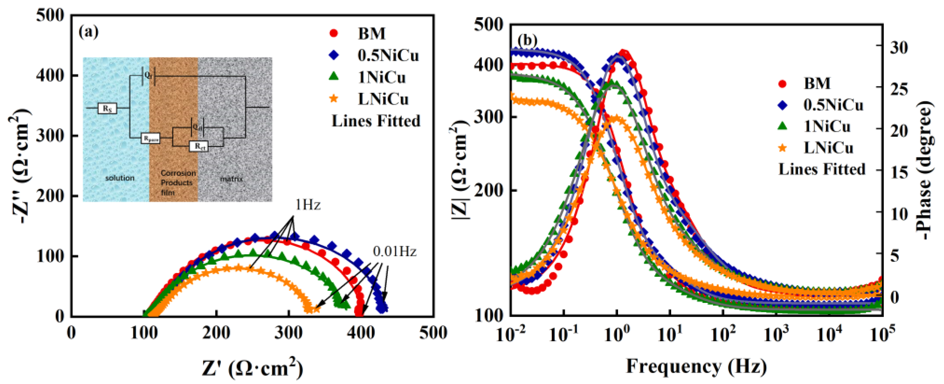
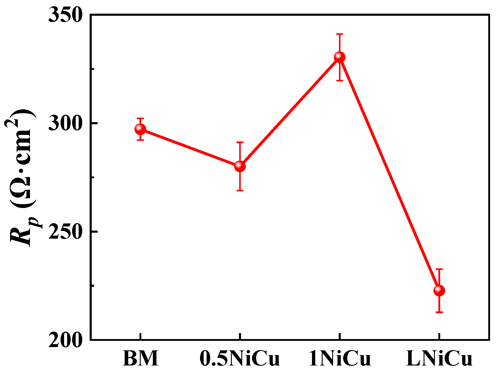
3.3.1. EIS Analysis

The EIS test results of the four test steels in the simulated mine environment are shown in Figure 5. All the Nyquist plots present a compressed semicircle, indicating a similar electrochemical mechanism. The semicircle radius of the 1NiCu steel is the biggest, which indicates that 1NiCu exerts the highest corrosion resistance. The Bode diagram indicates the existence of two time constants, and the Bode phase angle in Figure 5b is approximately 30° and far less than 90° on account of the porous corrosion product layer. Therefore, the equivalent electric circuit in the inset in Figure 5a with two time constants is used to fit the EIS curves, where Rs represents the solution resistance, and Rct and Rpore are the charge transfer resistance and corrosion product film resistance. Qdl and Qf are the constant-phase elements (CPEs) of the electric double layer and the corrosion product film, and the corresponding n values describe the deviation from an ideal capacitor caused by the inhomogeneity of the electrodes [20,21].
The fitted EIS values are listed in Table 4. The χ2 values are all at the 10−4 level, which indicates a high fitting quality. The values of Rct increase as a result of microalloying. In comparison to 1NiCu, Rct of LNiCu decreases and is lower than the BM. Therefore, it can be deduced that microalloying can suppress the charge transfer process, while decarburization accelerates charge transfer. The polarization resistance Rp (Rct + Rf) is used to characterize the corrosion resistance of the test steels, and the values are shown in Figure 6. It has been widely acknowledged that Rp is inversely proportional to the corrosion rate, so higher Rp values indicate a higher corrosion resistance [22]. By comparing Rp, we can conclude that 1NiCu presents the highest Rp value and corrosion resistance, and LNiCu exerts the lowest Rp and the worst corrosion resistance. In addition, 0.5NiCu exhibits a lower corrosion resistance than the BM, for Cu accelerates the generation of corrosion products and the corrosion process in the initial corrosion stage [23,24]. As a result, the corrosion resistance of Cr-bearing steels may decline. In addition, the beneficial effect of Cu on corrosion resistance makes a difference only when the content exceeds a certain value, so the corrosion resistance for 0.5NiCu is not markedly improved. The reason for the corrosion resistance differences is discussed thoroughly in the Discussion.

3.3.2. Polarization Curve Analysis

Potentiodynamic polarization curves for the anchor steels at the 0.5 mV/s scan rate are shown in Figure 7. All the curves present a similar shape, which is an indication of a similar corrosion mechanism. The anodic curves present the active dissolution reaction, and the cathodic branches exert a combination of the oxygen reduction reaction and hydrogen evolution reaction. The inset figures show that the anodic curve shifts to the left with the effect of alloy elements and decarburization in comparison to the BM, which indicates that both the microalloy and reducing the carbon content inhibit anodic dissolution. As for the cathodic branch, the cathodic polarization curves of 0.5NiCu and 1NiCu shift to the right, while the curve of LNiCu almost overlaps with that of the BM. Considering the opposite variation tendency of the cathodic branch and the anodic branch, we did not conduct Tafel fitting for corrosion rates as referred to in the literature [25]. The polarization curves of the three kinds of microalloyed steels vary slightly.

3.4. SSRT Results

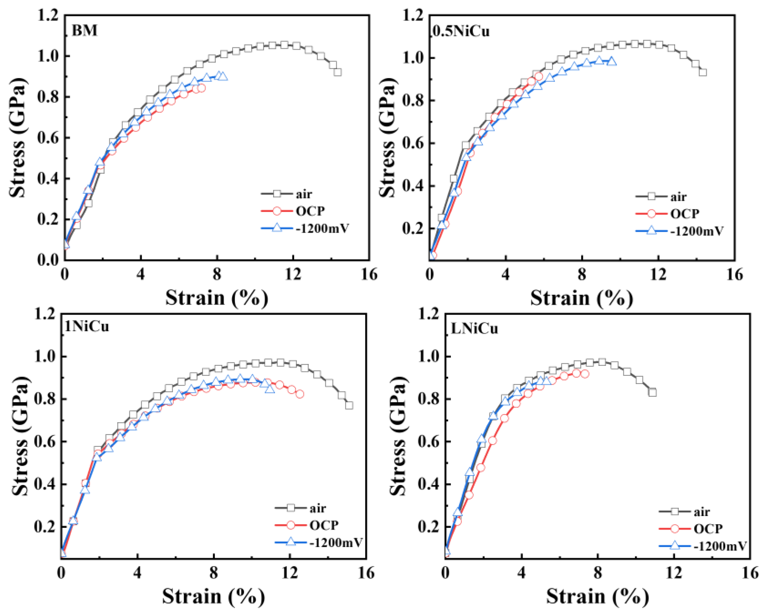
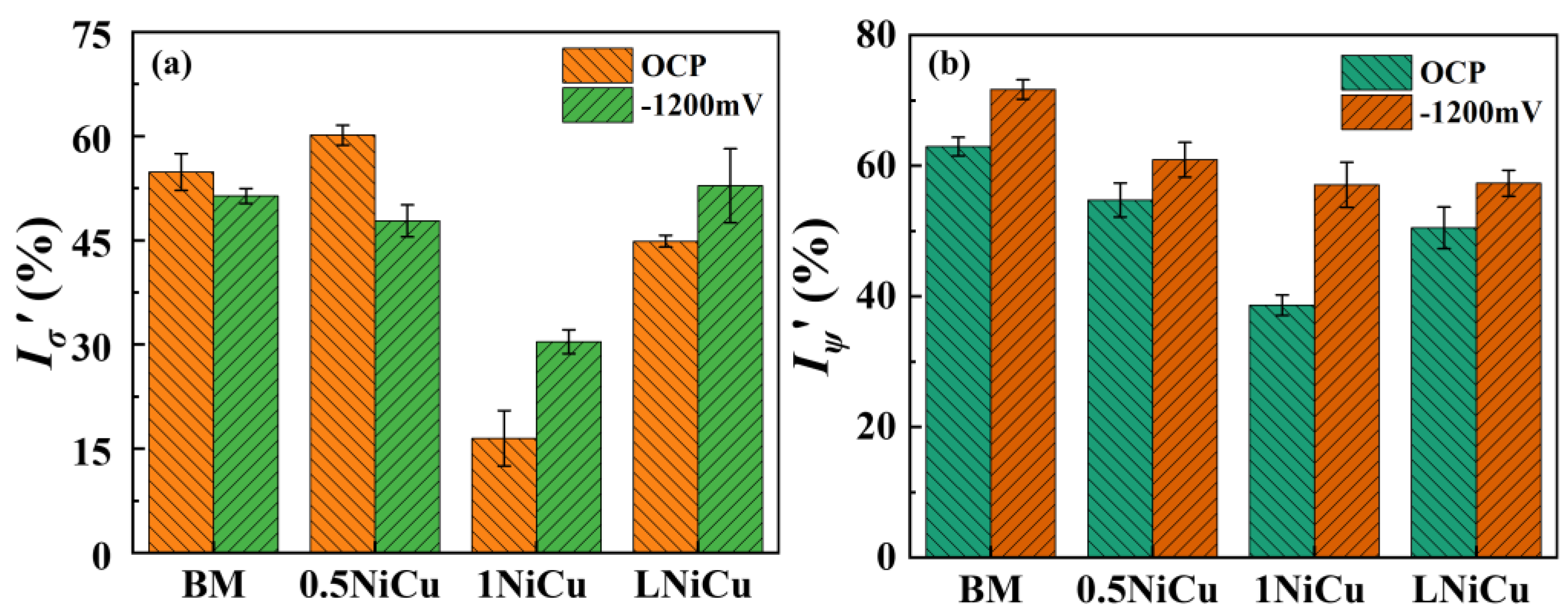
3.4.1. Stress–Strain Curves and SCC Susceptibility

Figure 8 shows the SSRT stress–strain curves of the test anchor steels. In addition, the elongation loss of 1NiCu is the lowest in the test solution, indicating the highest SCC resistance. It is worth noting that the elongation of 0.5NiCu at −1200 mV is significantly higher than that at OCP, which is probably due to the hydrogen-induced plasticity effect. This phenomenon has been observed in previous work, which proves that hydrogen can release stress concentration at crack initiation sites, decreases the stress intensity, and postpones SCC initiation at the applied cathodic polarization [26,27].
The normalized SCC susceptibility results of the test anchor steels are shown in Figure 9. When tested at −1200 mV, all microalloyed steels are less SCC-susceptible compared to the BM. Additionally, 1NiCu presents the highest SCC resistance at OCP and −1200 mV. Compared to the BM, the Iσ’ of 1NiCu reduces by over 70% when tested at OCP, and reduces by 45% when tested at −1200 mV. LNiCu presents higher SCC susceptibility than 1NiCu. The reason is that the excessively low carbon content is harmful to the stability of austenite [28], which also causes microstructure degradation during phase transformation and deformation, leading to lower SCC susceptibility.

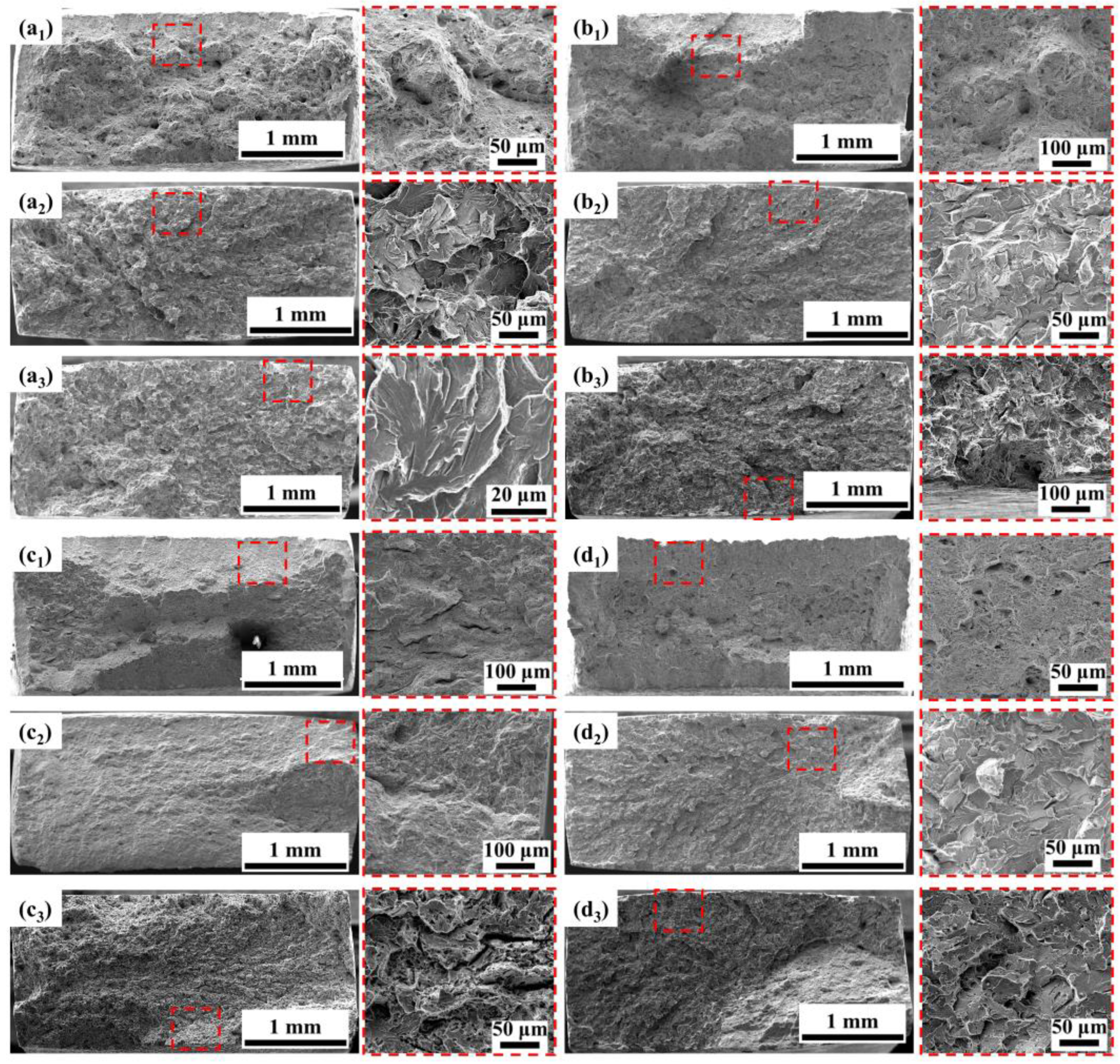
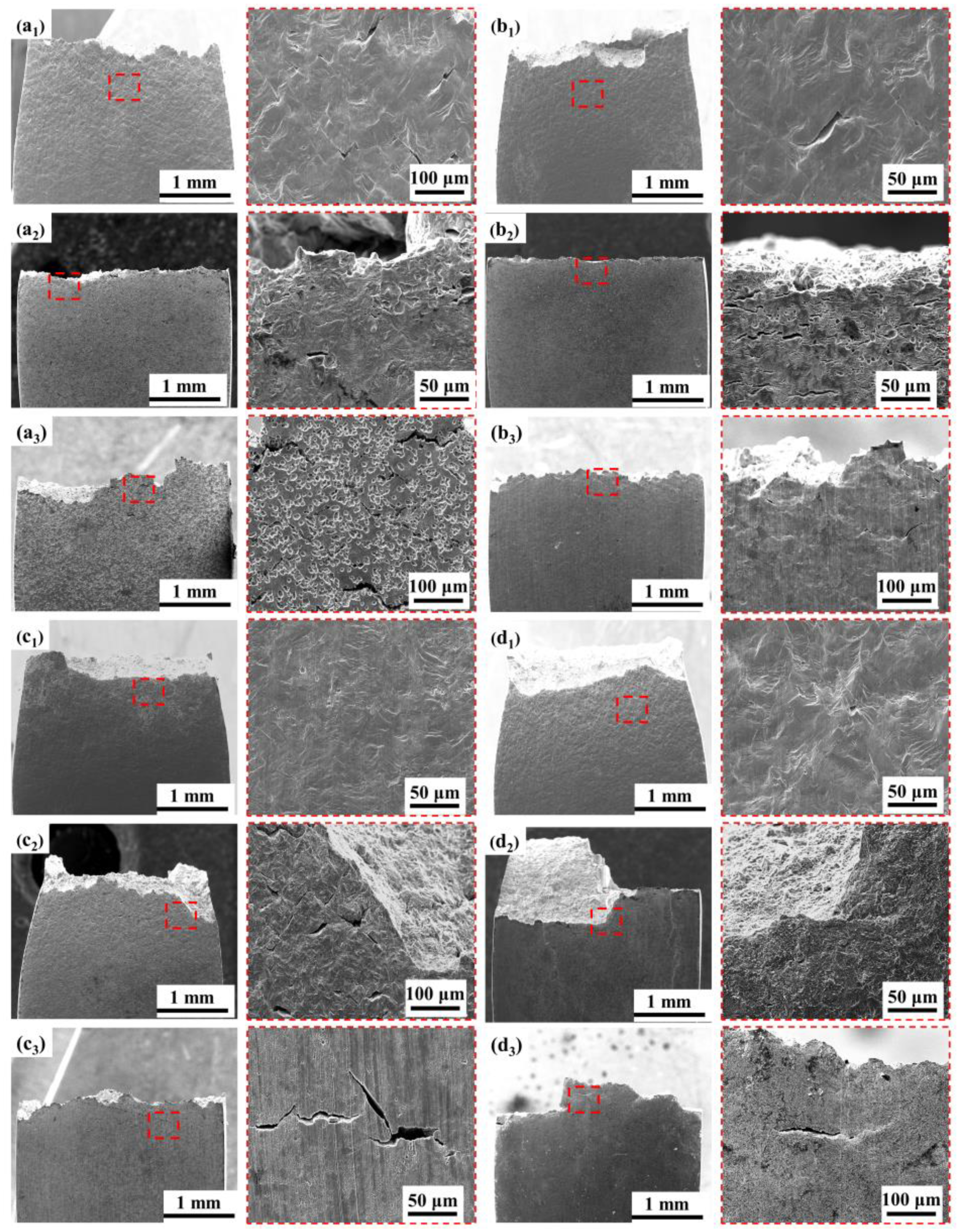
3.4.2. Fracture Analysis

After the SSRT tests, the fracture morphology of the anchor steels was carefully observed as shown in Figure 10. When the BM is tested in the air, there is obvious necking. In addition, dimples of different sizes are observed in the magnified view in Figure 10(a1), which are typical ductile fracture features. When tested in solution at OCP, the size and number of dimples decrease sharply, and brittle characteristics appear, indicating high SCC susceptibility. At −1200 mV, the brittle characteristics become more obvious. The SCC initiation site at the edge of the specimen is characterized by river-like patterns with distinct tear ridges, which is typical of a quasi-cleavage fracture. In addition, the fracture morphology of the BM and 0.5NiCu under OCP exhibits a convergence of extended cracks in the center of the fracture. It is speculated that there are multiple crack initiation sites at the edge of the fracture, which propagate to the interior of the specimens and result in the final fracture at the center. In addition, at OCP, the fracture surface of the BM, 0.5NiCu, and LNiCu is flat, while the fracture morphology of 1NiCu still exhibits necking, demonstrating the highest SCC resistance, which is consistent with the results of SCC susceptibility in Figure 9.
Secondary cracks of the test anchor steels were also carefully analyzed after the SSRT tests, as seen in Figure 11, which shows the side surface of the specimens. When tested in air, secondary cracks are present on the side face of the tested BM specimen but are not apparent on the microalloyed steels. When tested in solution, secondary cracks can be observed in all test specimens. At OCP, cracks with a big, open mouth can be observed, which is a sign of SCC caused by localized AD [29]. When tested at −1200 mV, the cracks are thin and shallow, which are typical of hydrogen-induced cracking (HIC) [30]. In addition, at OCP, the BM and 0.5NiCu show obvious pitting corrosion, which is less evident in the 1NiCu and LNiCu specimens as more Ni and Cu inhibit localized AD. At −1200 mV, in comparison to 1NiCu, the secondary cracks of LNiCu are longer and deeper, which indicates that the decreased C content deteriorates HE resistance. In summary, 1NiCu possesses the highest SCC resistance for inhibiting both AD and HE.

4. Discussion

4.1. Effect of Alloy Elements on the Electrochemical Mechanism

The underground mine environment is a harsh corrosive medium with multiphase flow containing CO2, SO2, and H2S. These gases are dissolved in water and form CO32− and HSO3. Therefore, the steel surface is covered with an acidic electrolyte film, which facilitates corrosion. In the coal mine environment, H2S and SO2 dissolve in the thin liquid film and form HSO3, which acidifies the electrolyte film [11,31]. Additionally, HSO3 is unstable and can be easily oxidized to H2SO4, which further acidifies the electrolyte film, as shown in chemical reaction Equation (5) [32].
2HSO3 + O2 → SO42− + 2H+
In consequence, anchor steels suffer from severe corrosion problems, and the electrochemical process is as follows. The anodic reaction is the dissolution of iron:
Fe + 2e → Fe2+
The cathodic reaction is the combination of oxygen reduction and hydrogen evolution:
O2 + 4e + 4H+ → 2H2O
2H+ + 2e → H2
The results in this work prove that microalloying improves corrosion resistance by making a difference in the electrochemical process, which inhibits anodic dissolution and accelerates the cathodic process as illustrated in Figure 7. Compared to the BM, the microalloyed steels Sb, Nb, Ni, and Cu were added, and the content of C was reduced in 1NiCu and LNiCu. The role of the discrete alloying elements is discussed as follows.
As for the effect of Sb, based on the Pourbaix diagram [33], Sb mainly exists in the form of Sb2O3 and Sb2O5 in the rust layer [34,35]. The reaction of Sb in the corrosion process is as follows:
2Sb + 3H2O → Sb2O3 + 6H+ + 6e
Sb2O3 + 2H2O → Sb2O5 + 4H+ + 4e
During the process, H+ can be produced simultaneously, which can inhibit the anodic reactions and reduction of HSO3. Thus, Sb inhibits anodic dissolution and enhances corrosion resistance. Additionally, Sb can interact with Cu and facilitate the formation of Cu-containing compounds in the product film, as reported in Le’s work [36], inhibiting the anodic dissolution process. Nb can form NbC nanoprecipitates, which act as hydrogen traps and improve HE resistance.
As for Cu effects, Cu inhibits anodic dissolution by promoting the formation of protective corrosion product film, but the improvement is obvious only when the addition exceeds a critical value. In addition, at the early stage of corrosion before forming the protective rust layer, Cu accelerates the corrosion process. As a result, the polarization resistance of 0.5NiCu is lower than the BM. 1NiCu exhibits a high resistance to corrosion and SCC with greater Cu and Ni contents. Ni is present in the rust layer as protective divalent products, including NiFe2O4, which has a negative electrical effect [37]. NiFe2O4 can make the inner rust layer generate cation selectivity to effectively resist corrosive ions and significantly alleviate the corrosion behavior of low-alloy, high-strength steel [38].
As for the effect of C, studies have shown that many hydrogen defects appear in the microstructure of high-strength steel after fracture in a humid environment. Thus, hydrogen entering the matrix will accumulate in special microstructures, such as carbides, reduce the interface bonding force, increase the cracking tendency of the interface, and promote the initiation and expansion of microcracks under the action of tensile stress. When the carbides grow, the large matrix–carbide boundary becomes a strong hydrogen trap, so the susceptibility to hydrogen embrittlement increases [39,40]. Figure 11 proves that the BM steel has many deep corrosion pits, possibly due to the presence of carbides, and preferential corrosion occurs around the carbides. 0.5NiCu steel without decarburization treatment shows the same problem. After the decarburization treatment of 1NiCu and LNiCu, the number of corrosion pits on the side of the fracture significantly decreases. Therefore, the decarburization treatment helps to reduce the hydrogen collection in the matrix.

4.2. Effect of Alloy Elements on the SCC Mechanism

Potentiodynamic curves at the slow scan rate of 0.5 mV/s and fast scan rate of 200 mV/s were used to clarify the effect of microalloying on electrochemical factors. The potentiodynamic polarization curves are shown in Figure 12. The comparison of the steady state and steady-state stress corrosion mechanisms identifies three regions with different corrosion mechanisms: AD, AD + HE, and HE [41,42].
Liu [42] proposed to quickly predict the potential range of each mechanism through the fast and slow sweep polarization curves and preliminarily determine the stress corrosion mechanism. According to Figure 12, the potential ranges that correspond to the stress corrosion mechanisms of the four low-alloy, high-strength steels can be determined as shown in Figure 12, and the specific data are shown in Table 5. Adding microalloying elements increases the potential range of the AD mechanism, indicating that Ni, Nb, and Sb have an inhibitory effect on anodic dissolution ability. In a similar study, Zhang [43] found that bainitic steels were more resistant to HE after adding 0.055% Nb. Both reversible and irreversible hydrogen traps are increased by Nb in steels [44,45]. It is speculated that the improvement of the hydrogen evolution corrosion potential largely depends on Nb.
With the decrease in carbon content, the anodic dissolution potential range of the 0.5NiCu and LNiCu low-alloy steels hardly changes, which indicates that the decarburization treatment does not significantly affect the anodic dissolution. With the addition of microalloying elements, the potential range of the HE mechanism slightly increases. With identical microalloying, the potential range of the HE mechanism significantly moves up in the decarburization treatment, which indicates that decarburization has a certain inhibitory effect on hydrogen embrittlement. Studies have shown that the formation of crack-sensitive paths in the process of stress corrosion may be closely related to C atoms from grain boundary defects. The presence of carbon or transition carbides at grain boundaries increases the stress corrosion sensitivity. It inhibits the dislocation movement away from the plastic deformation region associated with the crack, so it provides an adsorption site for anions on the crack surface, reduces the binding of adjacent iron atoms, and causes rapid failure.

5. Conclusions

Several conclusions can be drawn from the results and discussion:
(1)
The four kinds of anchor steels have a similar microstructure, which is mainly composed of pearlite.
(2)
The combined addition Ni, Cu, and Sb can improve the mechanical properties of the anchor steel, while reducing C content decreases tensile strength as a result of the loss of the solution-strengthening effect.
(3)
The addition of Sb, Cu, Ni, and reducing the content of C enhances the resistance to corrosion and SCC by mitigating AD, while adding Nb improves SCC by inhibiting HE. The combined action of 1% Ni, 0.5% Cu, 0.05% Nb, 0.1% Sb, and 0.5% C presents the highest SCC resistance.

Author Contributions

Methodology, H.D.; Validation, Y.P.; Formal analysis, Y.L.; Investigation, H.D., X.W., Z.L., A.J. and Y.P.; Resources, X.W. and Y.L.; Data curation, X.W.; Writing—original draft, H.D. and N.A.; Writing—review & editing, Z.L. and Y.P.; Visualization, N.A., Y.L. and A.J.; Supervision, Z.L.; Project administration, R.Y. and X.L.; Funding acquisition, R.Y. and X.L. All authors have read and agreed to the published version of the manuscript.

Funding

This research was funded by the National Natural Science Foundation of China (No. 52071017) and National Science and Technology Plan Projects of State Administration for Market Regulation (No. 2021MK021).

Institutional Review Board Statement

Not applicable.

Informed Consent Statement

Not applicable.

Data Availability Statement

The raw/processed data required to reproduce these findings cannot be shared at this time as the data is related to an ongoing study.

Conflicts of Interest

The authors declare that they have no known competing financial interest or personal relationships that could have appeared to influence the work reported in this paper.

References

  1. Li, X.; Zhang, D.; Liu, Z.; Li, Z.; Du, C.; Dong, C. Share Corrosion Data. Nature 2015, 527, 441–442. [Google Scholar] [CrossRef] [PubMed]
  2. Wang, Y.; Sun, X.; Ren, A. Investigations of Rock Anchor Corrosion and Its Influence Factors by Exhumations in Four Typical Field Sites. Eng. Fail. Anal. 2019, 101, 357–382. [Google Scholar] [CrossRef]
  3. Ananda Rao, M.; Sekhar Babu, R.; Pavan Kumar, M.V. Stress Corrosion Cracking Failure of a SS 316L High Pressure Heater Tube. Eng. Fail. Anal. 2018, 90, 14–22. [Google Scholar] [CrossRef]
  4. Bestautte, J.; Kalácska, S.; Béchet, D.; Obadia, Z.; Christien, F. Investigation of Quasi-Cleavage in a Hydrogen Charged Maraging Stainless Steel. Corros. Sci. 2023, 218, 111163. [Google Scholar] [CrossRef]
  5. Das, T.; Brahimi, S.V.; Song, J.; Yue, S. A Fast Fracture Approach to Assess Hydrogen Embrittlement (HE) Susceptibility and Mechanism(s) of High Strength Martensitic Steels. Corros. Sci. 2021, 190, 109701. [Google Scholar] [CrossRef]
  6. Yang, L.; Liu, Z.; Yang, X.; Xu, X.; Cheng, X.; Li, X. Behavior and Evaluation of Stress Corrosion Cracking of Typical Anchor Bolt Steel in Simulated Crevice Environment. J. Mater. Res. Technol. 2023, 25, 7430–7443. [Google Scholar] [CrossRef]
  7. Matos, T.S.; Portella, K.F.; Henke, S.L.; Bragança, M.O.G.P.; Galvão, M.P.; Dias, B.G.; Lagoeiro, L.; Almeida, L.M. Analysis of Anchor Rod Failure in a Guyed Transmission Tower: Influence of Microstructures and Corrosion Mechanisms. Eng. Fail. Anal. 2021, 121, 105166. [Google Scholar] [CrossRef]
  8. Cano, H.; Díaz, I.; De La Fuente, D.; Chico, B.; Morcillo, M. Effect of Cu, Cr and Ni Alloying Elements on Mechanical Properties and Atmospheric Corrosion Resistance of Weathering Steels in Marine Atmospheres of Different Aggressivities. Mater. Corros. 2018, 69, 8–19. [Google Scholar] [CrossRef]
  9. Zhou, Y.; Chen, J.; Xu, Y.; Liu, Z. Effects of Cr, Ni and Cu on the Corrosion Behavior of Low Carbon Microalloying Steel in a Cl− Containing Environment. J. Mater. Sci. Technol. 2013, 29, 168–174. [Google Scholar] [CrossRef]
  10. Cano, H.; Neff, D.; Morcillo, M.; Dillmann, P.; Diaz, I.; De La Fuente, D. Characterization of Corrosion Products Formed on Ni 2.4 wt%–Cu 0.5 wt%–Cr 0.5 wt% Weathering Steel Exposed in Marine Atmospheres. Corros. Sci. 2014, 87, 438–451. [Google Scholar] [CrossRef]
  11. Wu, W.; Liu, Z.; Wang, Q.; Li, X. Improving the Resistance of High-Strength Steel to SCC in a SO2-Polluted Marine Atmosphere through Nb and Sb Microalloying. Corros. Sci. 2020, 170, 108693. [Google Scholar] [CrossRef]
  12. Zhang, C.; Hui, W.; Zhao, X.; Zhang, Y.; Zhao, X. The Potential Significance of Microalloying with Nb in Enhancing the Resistance to Hydrogen-Induced Delayed Fracture of 1300-MPa-Grade High-Strength Bolt Steel. Eng. Fail. Anal. 2022, 135, 106144. [Google Scholar] [CrossRef]
  13. Shi, R.; Ma, Y.; Wang, Z.; Gao, L.; Yang, X.-S.; Qiao, L.; Pang, X. Atomic-Scale Investigation of Deep Hydrogen Trapping in NbC/α-Fe Semi-Coherent Interfaces. Acta Mater. 2020, 200, 686–698. [Google Scholar] [CrossRef]
  14. Chen, W.; Zhou, R.; Li, W.; Chen, Y.-H.; Chou, T.-H.; Wang, X.; Liu, Y.; Zhu, Y.; Huang, J.C. Effect of Interstitial Carbon and Nitrogen on Corrosion of FeCoCrNi Multi-Principal Element Alloys Made by Selective Laser Melting. J. Mater. Sci. Technol. 2023, 148, 52–63. [Google Scholar] [CrossRef]
  15. GB/T 228.1-2021; Metallic materials—Tensile testing—Part 1: Method of test at room temperature. Standardization Administration of the People’s Republic of China: Beijing, China, 2021.
  16. Parkins, R.N. Predictive Approaches to Stress Corrosion Cracking Failure. Corros. Sci. 1980, 20, 147–166. [Google Scholar] [CrossRef]
  17. Ding, Z.; Liang, B.; Xu, Z.; Tian, R.; Dong, L.; Zhao, J. Formation and Morphology of Grain Boundary Proeutectoid Pearlite in 100Mn13 Steel during Low Temperature Aging Treatment. Mater. Today Commun. 2022, 33, 104887. [Google Scholar] [CrossRef]
  18. Jung, M.; Cho, W.; Park, J.; Jung, J.-G.; Lee, Y.-K. Variation of Carbon Concentration in Proeutectoid Ferrite during Austenitization in Hypoeutectoid Steel. Mater. Charact. 2014, 94, 161–169. [Google Scholar] [CrossRef]
  19. Xiong, J.; Liu, E.; Zhang, C.; Kong, L.; Yang, H.; Zhang, X.; Wang, Y. Tuning Mechanical Behavior and Deformation Mechanisms in High-Manganese Steels via Carbon Content Modification. Mater. Sci. Eng. A 2023, 881, 145401. [Google Scholar] [CrossRef]
  20. Qiao, C.; Wang, M.; Hao, L.; Jiang, X.; Liu, X.; Thee, C.; An, X. In-Situ EIS Study on the Initial Corrosion Evolution Behavior of SAC305 Solder Alloy Covered with NaCl Solution. J. Alloys Compd. 2021, 852, 156953. [Google Scholar] [CrossRef]
  21. Brug, G.J.; van den Eeden, A.L.; Sluyters-Rehbach, M.; Sluyters, J.H. The Analysis of Electrode Impedances Complicated by the Presence of a Constant Phase Element. J. Electroanal. Chem. Interfacial Electrochem. 1984, 176, 275–295. [Google Scholar] [CrossRef]
  22. Sun, B.; Pan, Y.; Yang, J.; Guo, J.; Zhao, B.; Liu, X.; Liu, Z.; Li, X. Microstructure Evolution and SSCC Behavior of Strain-Strengthened 304 SS Pre-Strained at Room Temperature and Cryogenic Temperature. Corros. Sci. 2023, 210, 110855. [Google Scholar] [CrossRef]
  23. Zhang, T.; Liu, W.; Dong, B.; Yang, W.; Chen, L.; Sun, Y.; Li, H.; Zhang, B. Clarifying the Effect of Cu Element on the Corrosion Properties of Ni-Mo Low Alloy Steel in Marine Environment. Corros. Sci. 2023, 216, 111107. [Google Scholar] [CrossRef]
  24. Zhang, T.; Liu, W.; Dong, B.; Mao, R.; Sun, Y.; Chen, L. Corrosion of Cu-Doped Ni–Mo Low-Alloy Steel in a Severe Marine Environment. J. Phys. Chem. Solids 2022, 163, 110584. [Google Scholar] [CrossRef]
  25. Tian, H.; Cui, Z.; Ma, H.; Zhao, P.; Yan, M.; Wang, X.; Cui, H. Corrosion Evolution and Stress Corrosion Cracking Behavior of a Low Carbon Bainite Steel in the Marine Environments: Effect of the Marine Zones. Corros. Sci. 2022, 206, 110490. [Google Scholar] [CrossRef]
  26. Liu, Z.Y.; Wang, X.Z.; Du, C.W.; Li, J.K.; Li, X.G. Effect of Hydrogen-Induced Plasticity on the Stress Corrosion Cracking of X70 Pipeline Steel in Simulated Soil Environments. Mater. Sci. Eng. A 2016, 658, 348–354. [Google Scholar] [CrossRef]
  27. Pan, Y.; Liu, Z.; Zhang, Y.; Li, X.; Du, C. Effect of AC Current Density on the Stress Corrosion Cracking Behavior and Mechanism of E690 High-Strength Steel in Simulated Seawater. J. Mater. Eng. Perform. 2019, 28, 6931–6941. [Google Scholar] [CrossRef]
  28. Seol, J.-B.; Jung, J.E.; Jang, Y.W.; Park, C.G. Influence of Carbon Content on the Microstructure, Martensitic Transformation and Mechanical Properties in Austenite/ε-Martensite Dual-Phase Fe–Mn–C Steels. Acta Mater. 2013, 61, 558–578. [Google Scholar] [CrossRef]
  29. Liu, X.; Wu, M.; Wang, X.; Gong, K.; Du, J.; Huang, J.C.; Hu, M. Stress Corrosion Cracking Behavior of X80 Steel under the Combined Effects of Sulfide and Cathodic Potential. J. Mater. Res. Technol. 2023, 24, 3925–3936. [Google Scholar] [CrossRef]
  30. Pan, Y.; Sun, B.; Liu, Z.; Wu, W.; Li, X. Hydrogen Effects on Passivation and SCC of 2205 DSS in Acidified Simulated Seawater. Corros. Sci. 2022, 208, 110640. [Google Scholar] [CrossRef]
  31. Li, K.; Zeng, Y. Long-Term Corrosion and Stress Corrosion Cracking of X65 Steel in H2O-Saturated Supercritical CO2 with SO2 and O2 Impurities. Constr. Build. Mater. 2023, 362, 129746. [Google Scholar] [CrossRef]
  32. Niu, J.; Tang, Z.; Huang, H.; Pei, J.; Zhang, H.; Yuan, G.; Ding, W. Research on a Zn-Cu Alloy as a Biodegradable Material for Potential Vascular Stents Application. Mater. Sci. Eng. C 2016, 69, 407–413. [Google Scholar] [CrossRef]
  33. Gu, T.; Teng, W.; Liu, A.; Deng, Z.; Ling, L.; Zhang, W. Transformation of Nanoscale Zero-Valent Iron with Antimony: Effects of the Sb Spatial Configuration. Chem. Eng. J. 2021, 416, 129073. [Google Scholar] [CrossRef]
  34. Yang, Y.; Cheng, X.; Zhao, J.; Fan, Y.; Li, X. A Study of Rust Layer of Low Alloy Structural Steel Containing 0.1% Sb in Atmospheric Environment of the Yellow Sea in China. Corros. Sci. 2021, 188, 109549. [Google Scholar] [CrossRef]
  35. Li, J.; Chen, J.; Song, J.; Zhang, X.; Li, Z.; Luo, H.; Yu, W.; Dong, C.; Xiao, K. Research on Corrosion Behavior of Truck Body Steel in Chlorine-Containing Sulfuric Acid Environment. J. Mater. Res. Technol. 2022, 21, 1878–1889. [Google Scholar] [CrossRef]
  36. Le, D.P.; Ji, W.S.; Kim, J.G.; Jeong, K.J.; Lee, S.H. Effect of Antimony on the Corrosion Behavior of Low-Alloy Steel for Flue Gas Desulfurization System. Corros. Sci. 2008, 50, 1195–1204. [Google Scholar] [CrossRef]
  37. Wang, Y.; Li, J.; Zhang, L.; Zhang, L.; Wang, Q.; Wang, T. Structure of the Rust Layer of Weathering Steel in A High Chloride Environment: A Detailed Characterization via HRTEM, STEM-EDS, and FIB-SEM. Corros. Sci. 2020, 177, 108997. [Google Scholar] [CrossRef]
  38. Yu, Q.; Yang, X.; Dong, W.; Wang, Q.; Zhang, F.; Gu, X. Layer-by-Layer Investigation of the Multilayer Corrosion Products for Different Ni Content Weathering Steel via a Novel Pull-off Testing. Corros. Sci. 2022, 195, 109988. [Google Scholar] [CrossRef]
  39. Maetz, J.-Y.; Douillard, T.; Cazottes, S.; Verdu, C.; Kléber, X. M23C6 Carbides and Cr2N Nitrides in Aged Duplex Stainless Steel: A SEM, TEM and FIB Tomography Investigation. Micron 2016, 84, 43–53. [Google Scholar] [CrossRef] [PubMed]
  40. Wang, T.; Zhang, H.; Liang, W. Hydrogen Embrittlement Fracture Mechanism of 430 Ferritic Stainless Steel: The Significant Role of Carbides and Dislocations. Mater. Sci. Eng. A 2022, 829, 142043. [Google Scholar] [CrossRef]
  41. Song, L.; Liu, Z.; Li, X.; Du, C. Characteristics of Hydrogen Embrittlement in High-PH Stress Corrosion Cracking of X100 Pipeline Steel in Carbonate/Bicarbonate Solution. Constr. Build. Mater. 2020, 263, 120124. [Google Scholar] [CrossRef]
  42. Liu, Z.Y.; Lu, L.; Huang, Y.Z.; Du, C.W.; Li, X.G. Mechanistic Aspect of Non-Steady Electrochemical Characteristic During Stress Corrosion Cracking of an X70 Pipeline Steel in Simulated Underground Water. Corrosion 2014, 70, 678–685. [Google Scholar] [CrossRef] [PubMed]
  43. Zhang, S.; Zhao, Q.; Liu, J.; Huang, F.; Huang, Y.; Li, X. Understanding the Effect of Niobium on Hydrogen-Induced Blistering in Pipeline Steel: A Combined Experimental and Theoretical Study. Corros. Sci. 2019, 159, 108142. [Google Scholar] [CrossRef]
  44. Vercruysse, F.; Claeys, L.; Depover, T.; Verleysen, P.; Petrov, R.H.; Verbeken, K. The Effect of Nb on the Hydrogen Embrittlement Susceptibility of Q&P Steel under Static and Dynamic Loading. Mater. Sci. Eng. A 2022, 852, 143652. [Google Scholar] [CrossRef]
  45. Samanta, S.; Gangavarapu, S.; Jayabalan, B.; Makineni, S.K.; Dutta, M.; Singh, S.B. Atomic-Scale Investigation of H-Trapping by Fine NbC Precipitates in a Low C Ferritic Steel. Scr. Mater. 2023, 234, 115537. [Google Scholar] [CrossRef]
Figure 1. Schematic diagram of the heat treatment process for the prepared low-alloy anchor steels.
Materials 16 05965 g001
Figure 2. Schematic diagram of tensile specimens.
Materials 16 05965 g002
Figure 3. Microstructures of the prepared low-alloy, high-strength anchor steels: (a) BM; (b) 0.5NiCu; (c) 1NiCu; (d) LNiCu.
Materials 16 05965 g003
Figure 4. Stress–strain curves of the four kinds of anchor steels.
Materials 16 05965 g004
Figure 5. (a) Nyquist and (b) Bode plots of the prepared microalloyed anchor steels in a coal mine environment.
Materials 16 05965 g005
Figure 6. Statistical results of polarization resistance of the four kinds of anchor steels.
Materials 16 05965 g006
Figure 7. Polarization curves of the prepared microalloyed anchor steels in a coal mine environment.
Materials 16 05965 g007
Figure 8. Stress–strain curves of the anchor steels after SSRT tests in air and simulated mine environment.
Materials 16 05965 g008
Figure 9. Normalized SCC susceptibility of the test anchor steels (a) I σ x and (b) I Ψ x .
Materials 16 05965 g009
Figure 10. Fracture morphology of different test steels after SSRT tests in various test conditions: (a1) BM in air; (a2) BM at OCP; (a3) BM at −1200 mV; (b1) 0.5NiCu in air; (b2) 0.5NiCu at OCP; (b3) 0.5NiCu at −1200 mV; (c1) 1NiCu in air; (c2) 1NiCu at OCP; (c3) 1NiCu at −1200 mV; (d1) LNiCu in air; (d2) LNiCu at OCP; (d3) LNiCu at −1200 mV (The red squares show the crack initiation sites and the typical morphology).
Materials 16 05965 g010
Figure 11. Morphology of secondary cracks of different test steels after SSRT tests in various test conditions: (a1) BM in air; (a2) BM at OCP; (a3) BM at −1200 mV; (b1) 0.5NiCu in air; (b2) 0.5NiCu at OCP; (b3) 0.5NiCu at −1200 mV; (c1) 1NiCu in air; (c2) 1NiCu at OCP; (c3) 1NiCu at −1200 mV; (d1) LNiCu in air; (d2) LNiCu at OCP; (d3) LNiCu at −1200 mV (The red tangles are key observation areas and the morphology at magnified view).
Materials 16 05965 g011
Figure 12. Potentiodynamic polarization curves of prepared steels at 0.5 mV/s and 200 mV/s sweep speeds.
Materials 16 05965 g012
Table 1. The chemical compositions (wt.%) of the tested anchor steels.
CSiMnCrNiCuNbSbPS
BM0.710.210.800.2000000.0180.002
0.5NiCu0.710.210.800.200.490.510.0460.110.0210.016
1NiCu0.530.210.800.200.980.510.0460.110.0220.012
LNiCu0.340.210.800.200.980.510.0460.110.0150.014
Table 2. The chemical composition of the simulated mine environment (g/L).
NaClKNO3Na2SO4NaHCO3NaHSO3
0.250.10.501.001.00
Table 3. The mechanical properties of the test steels.
SteelsTensile Strength (MPa)Yield Strength (MPa)Elongation Rate (%)Reduction in Area (%)
BM962 ± 85525 ± 579.14 ± 1.531.97 ± 2.9
0.5NiCu1046 ± 99604 ± 788.65 ± 1.232.73 ± 3.8
1NiCu907 ± 83557 ± 559.30 ± 2.045.65 ± 5.5
LNiCu856 ± 89551 ± 657.60 ± 1.537.01 ± 3.5
Table 4. Fitting results of the EIS curves of all test steels.
Steel Rs/Ω·cm2Qf × 10−4−1cm−2snnfRpore/Ω·cm2Qdl × 10−4−1cm−2snndlRct/Ω·cm2χ2 × 10−4
BM105.53.990.9357.375.940.95239.83.64
0.5NiCu 103.47.550.8232.2310.430.83247.81.53
1NiCu 107.14.770.8649.257.370.90281.12.05
LNiCu 111.76.930.8227.2211.90.82195.51.12
Table 5. Potential range corresponding to three stress corrosion mechanisms of the anchor steels (V vs. SCE).
SteelsADAD + HEHE
BM>−0.712 V−0.712~−0.867 V<−0.867 V
0.5NiCu>−0.692 V−0.857~−0.692 V<−0.857 V
1NiCu>−0.687 V−0.858~−0.687 V<−0.858 V
LNiCu>−0.689 V−0.836~−0.688 V<−0.836 V
Disclaimer/Publisher’s Note: The statements, opinions and data contained in all publications are solely those of the individual author(s) and contributor(s) and not of MDPI and/or the editor(s). MDPI and/or the editor(s) disclaim responsibility for any injury to people or property resulting from any ideas, methods, instructions or products referred to in the content.

