
Effect of Silane Coupling Agent Treatment of Aggregates on Mortar Workability, Strength and Interfacial Microscopic Properties

Abstract
:1. Introduction
2. Experiments
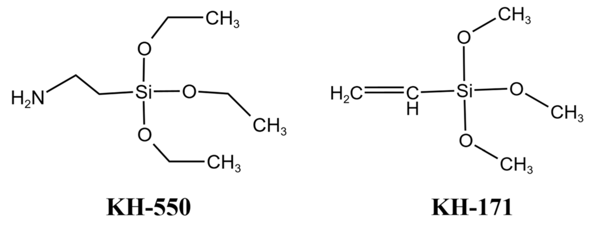
2.1. Materials
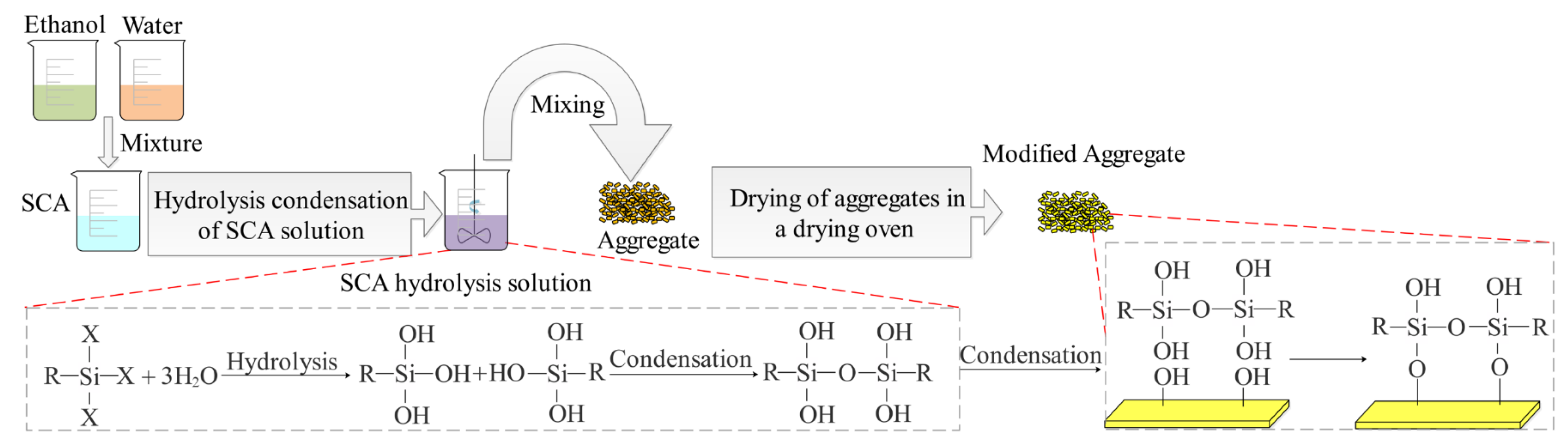
2.2. Surface Modification of Aggregates
2.3. Preparation and Curing of Mortar
2.4. Test Methods
2.4.1. X-ray Diffraction (XRD)
2.4.2. Fourier Transform Infrared Spectroscopy (FT-IR)
2.4.3. X-ray Photoelectron Spectroscopy (XPS)
2.4.4. Contact Angle
2.4.5. Fluidity
2.4.6. Mercury Intrusion Porosimeter (MIP)
2.4.7. SEM and Backscattered Electron Imaging (BSE)
2.4.8. Nanoindentation
2.4.9. Mechanical Properties
3. Results and Discussion
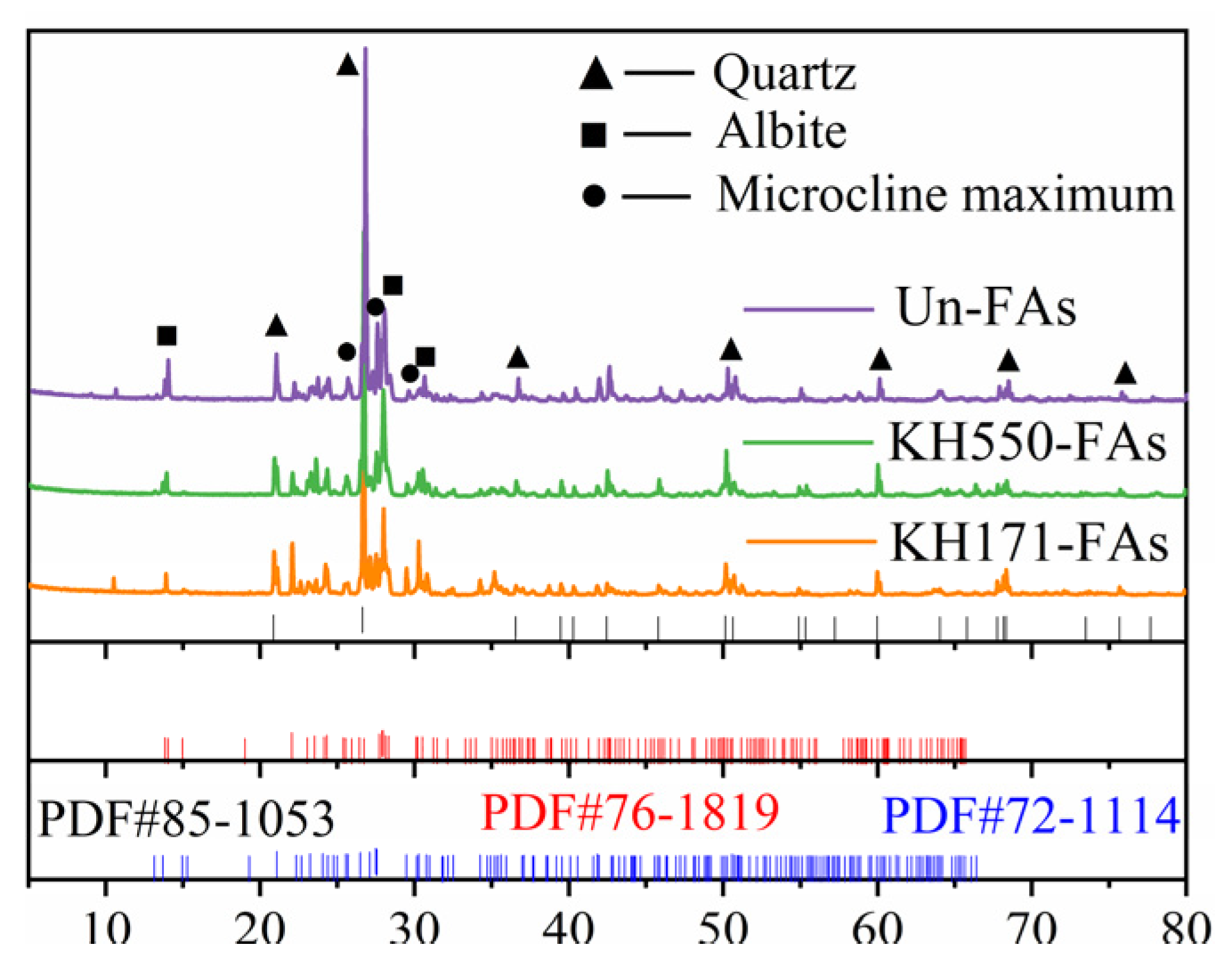
3.1. XRD
3.2. FT-IR
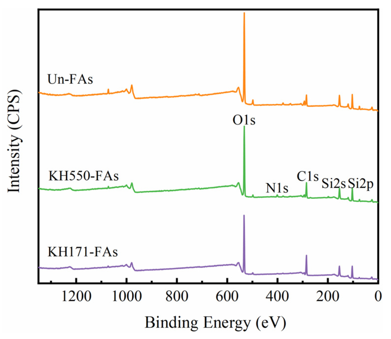
3.3. XPS
3.4. Contact Angle of Aggregate Surface
3.5. Water Absorption Rate of Aggregates
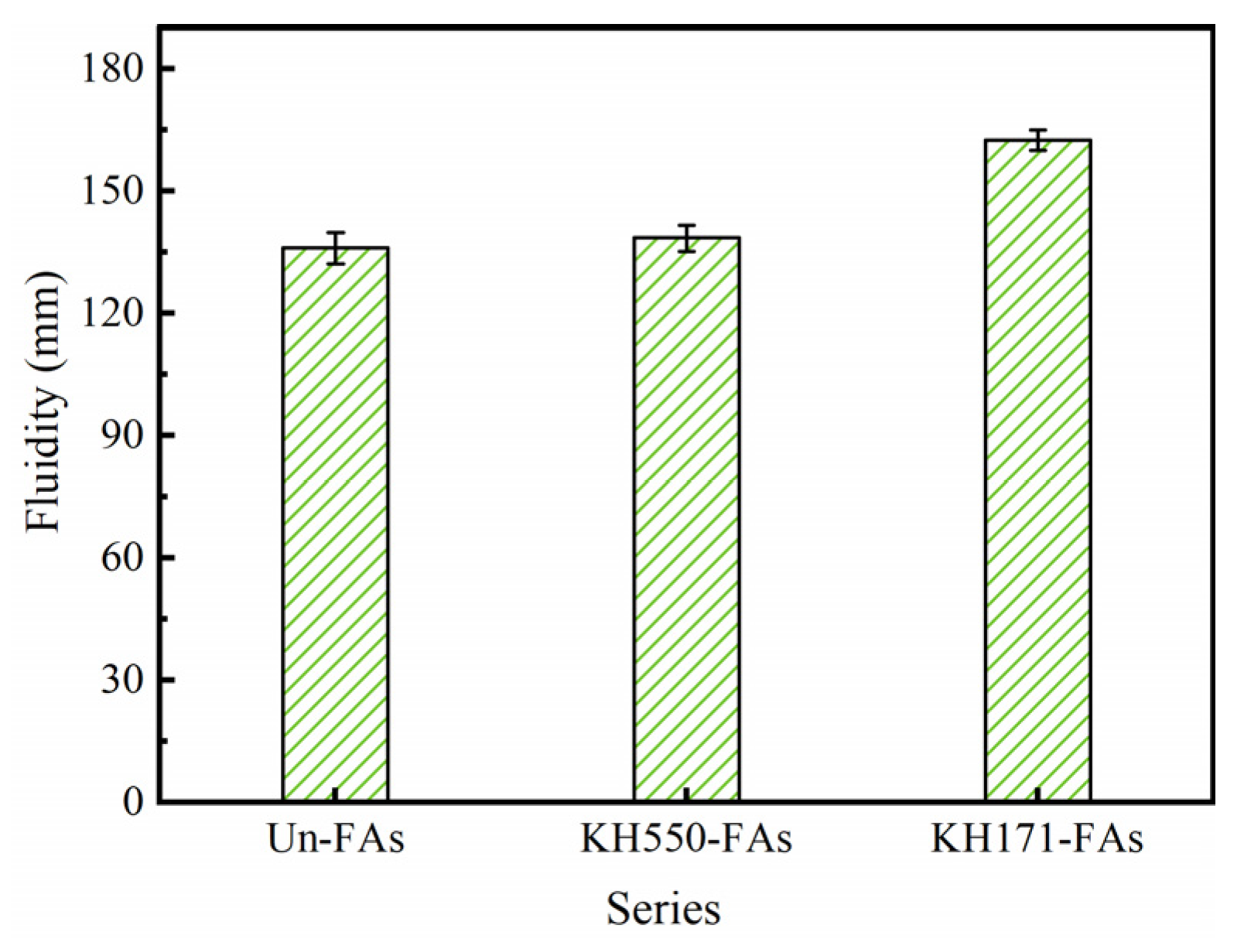
3.6. Fluidity of Mortar
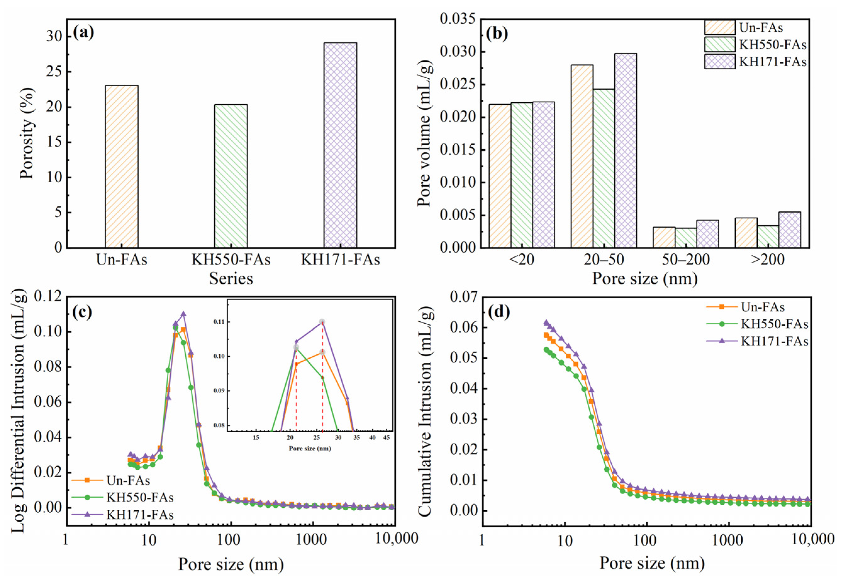
3.7. Porosity of Mortar
3.8. Microstructure of the Interface Transition Zone in Mortar
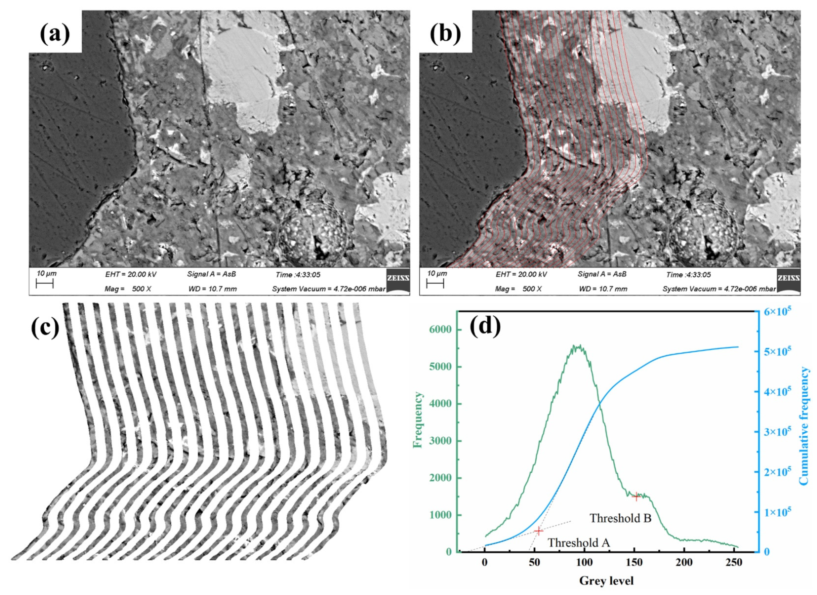
3.9. Backscattered Electron Imaging (BSE)
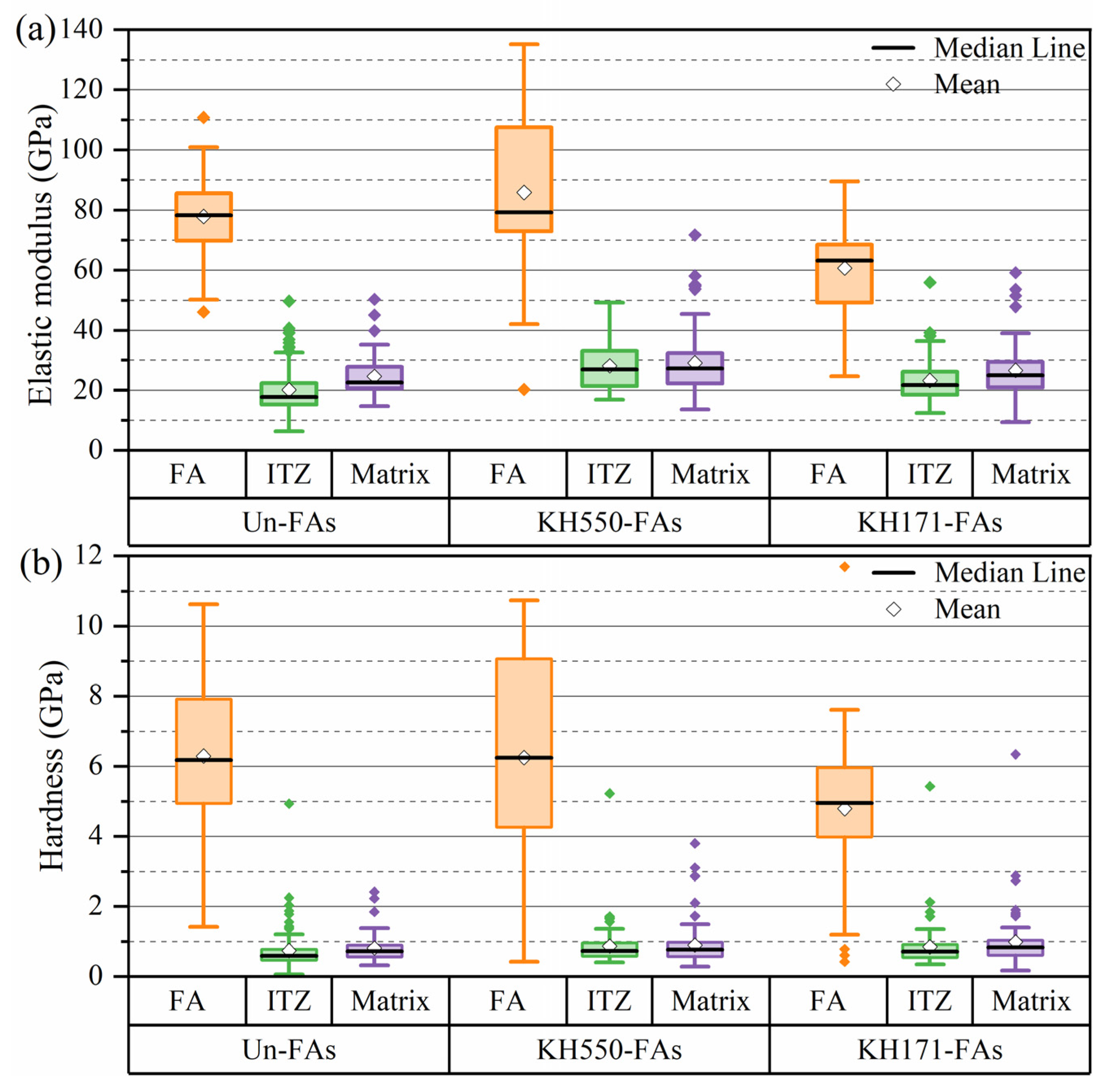
3.10. Nanoindentation
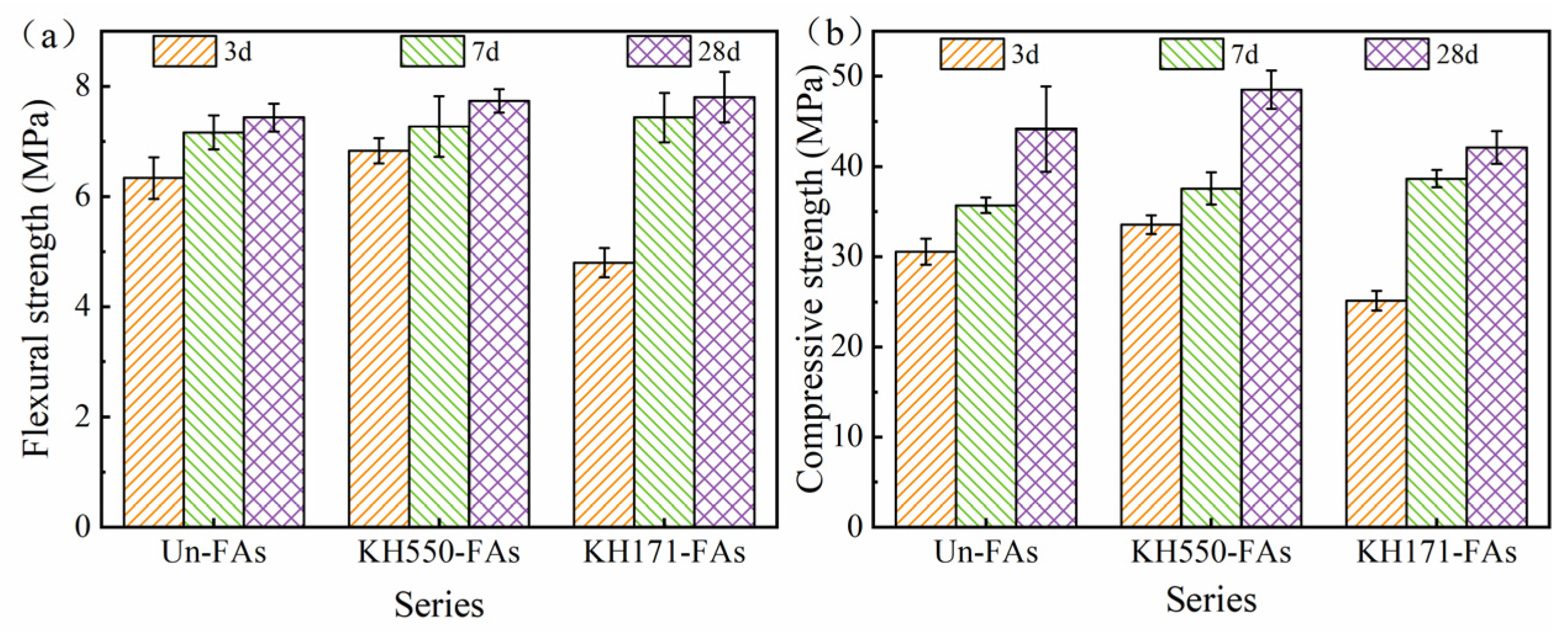
3.11. Mechanical Properties of Mortar
4. Conclusions
- The surface wettability of an aggregate affects the interface bonding property between the aggregate and the cement matrix. The order of the interfacial bond strength of different aggregate surface wettability is 59° > 23° > 91°. Therefore, an appropriate reduction in aggregate surface hydrophilicity can improve the interface bonding property.
- The mechanism of reducing the surface hydrophilicity of aggregates to improve the interface bonding property is as follows: After modifying the aggregates with KH550, the hydrophilicity of the aggregate surface decreases, resulting in a reduced ability to adsorb water on the surface. This leads to a decrease in the water content on the aggregate surface, which lowers the water-to-cement ratio at the interface and consequently reduces the porosity of the ITZ. The reduction in the water content on the aggregate surface allows the cementitious matrix to obtain more water for cement hydration, thereby enhancing the degree of hydration of the cementitious matrix.
- The microscopic test results show that the interfacial bonding properties and mechanical properties are enhanced by appropriately reducing the surface hydrophilicity of the aggregates. The variation in the pore volume fraction with a distance from the aggregate surface of 60 μm was quantitatively analyzed with backscattered electron images. The research shows that the hydrophilicity of the aggregate surface can reduce the interfacial porosity and improve the interfacial performance.
- The surface wettability of the aggregate changes from hydrophilic to hydrophobic, the interface bonding performance deteriorates, and the interface porosity increases. This is mainly due to the poor wettability of the aggregate surface. On the one hand, the addition of hydrophobic aggregates to the cement slurry introduces air bubbles, leading to interface discontinuity. On the other hand, the hydrophobic nature of the aggregates makes it difficult for water to spread onto the aggregate surface, resulting in poor interfacial bonding performance.
Author Contributions
Funding
Institutional Review Board Statement
Informed Consent Statement
Data Availability Statement
Conflicts of Interest
References
- Fu, C.Q.; Ling, Y.F.; Wang, K.J. An innovation study on chloride and oxygen diffusions in simulated interfacial transition zone of cementitious material. Cem. Concr. Compos. 2020, 110, 103585. [Google Scholar] [CrossRef]
- Prokopski, G.; Halbiniak, J. Interfacial transition zone in cementitious materials. Cem. Concr. Res. 2000, 30, 579–583. [Google Scholar] [CrossRef]
- Li, M.; Chen, H.; Qing, L.; Lin, J. Generalized implicit solution of ITZ percolation threshold and its effect on the diffusivity of concrete: Influence of aggregate shape- and size-polydispersities. Int. J. Heat Mass Transf. 2023, 200, 123514. [Google Scholar] [CrossRef]
- Sun, D.; Shi, H.; Wu, K.; Miramini, S.; Li, B.; Zhang, L. Influence of aggregate surface treatment on corrosion resistance of cement composite under chloride attack. Constr. Build. Mater. 2020, 248, 118636. [Google Scholar] [CrossRef]
- Zhang, S.; Liu, R.; Lu, C.; Gao, Y.; Xu, J.; Yao, L.; Chen, Y. Application of digital image correlation to study the influence of the water/cement ratio on the interfacial transition zone in cement-based materials. Constr. Build. Mater. 2023, 367, 130167. [Google Scholar] [CrossRef]
- Jalilifar, H.; Sajedi, F. Micro-structural analysis of recycled concretes made with recycled coarse concrete aggregates. Constr. Build. Mater. 2021, 267, 121041. [Google Scholar] [CrossRef]
- Li, C.-Z.; Song, X.-B.; Gu, X.-L. Modeling and experimental study on chloride migration of interfacial transition zone based on its pore structure. Constr. Build. Mater. 2022, 333, 127383. [Google Scholar] [CrossRef]
- Zhang, X.; Zhou, S.; Zhou, H.; Li, D. The effect of the modification of graphene oxide with γ-aminopropyltriethoxysilane (KH550) on the properties and hydration of cement. Constr. Build. Mater. 2022, 322, 126497. [Google Scholar] [CrossRef]
- Cheng, X.; Liu, J.; Han, C.; Zhang, X.; Wu, Z. Silane coupling agent impact on surface features of modification of basalt fibers and the rheological properties of basalt fiber reinforced asphalt. Constr. Build. Mater. 2023, 366, 130182. [Google Scholar] [CrossRef]
- Zhang, J.; Huang, F.; Wu, Y.; Fu, T.; Huang, B.; Liu, W.; Qiu, R. Mechanical properties and interface improvement of bamboo cellulose nanofibers reinforced autoclaved aerated concrete. Cem. Concr. Compos. 2022, 134, 104760. [Google Scholar] [CrossRef]
- Jiang, D.; Lv, S.; Jiang, D.; Xu, H.; Kang, H.; Song, X.; He, S. Effect of modification methods on water absorption and strength of wheat straw fiber and its cement-based composites. J. Build. Eng. 2023, 71, 106466. [Google Scholar] [CrossRef]
- Wang, J.; Wang, S.; Zuo, Y.; Xiao, J.; Wu, Y. Construction of compatible interface of straw/magnesium oxychloride lightweight composites by coupling agents. Constr. Build. Mater. 2021, 281, 122600. [Google Scholar] [CrossRef]
- Tian, S.; He, H.; Yu, P.; Zhou, L.; Luo, Y.; Jia, D. Sustainable utilization of waste printed circuit boards powders in HDPE-wood composites: Synergistic effects of multicomponents on structure and properties. J. Clean. Prod. 2017, 164, 840–847. [Google Scholar] [CrossRef]
- Chen, K.; Li, P.; Li, X.; Liao, C.; Li, X.; Zuo, Y. Effect of silane coupling agent on compatibility interface and properties of wheat straw/polylactic acid composites. Int. J. Biol. Macromol. 2021, 182, 2108–2116. [Google Scholar] [CrossRef]
- Zou, D.; Wang, D.; Zhang, S.; Li, H. Influence of self-dispersing particles on workability, hydration and strength of ultra-high-performance concrete. Constr. Build. Mater. 2022, 326, 126727. [Google Scholar] [CrossRef]
- Su, J.; Liu, M.; Lin, L.; Pu, X.; Ge, C.; Zhang, T.; Liu, G. Sulfonated lignin modified with silane coupling agent as biodegradable shale inhibitor in water-based drilling fluid. J. Pet. Sci. Eng. 2022, 208, 109618. [Google Scholar] [CrossRef]
- Min, Y.; Fang, Y.; Huang, X.; Zhu, Y.; Li, W.; Yuan, J.; Tan, L.; Wang, S.; Wu, Z. Surface modification of basalt with silane coupling agent on asphalt mixture moisture damage. Appl. Surf. Sci. 2015, 346, 497–502. [Google Scholar] [CrossRef]
- Li, H.; Wang, R.; Hu, H.; Liu, W. Surface modification of self-healing poly(urea-formaldehyde) microcapsules using silane-coupling agent. Appl. Surf. Sci. 2008, 255, 1894–1900. [Google Scholar] [CrossRef]
- Peng, C.; Chen, P.; You, Z.; Lv, S.; Zhang, R.; Xu, F.; Zhang, H.; Chen, H. Effect of silane coupling agent on improving the adhesive properties between asphalt binder and aggregates. Constr. Build. Mater. 2018, 169, 591–600. [Google Scholar] [CrossRef]
- Cui, B.; Wang, H. Molecular interaction of Asphalt-Aggregate interface modified by silane coupling agents at dry and wet conditions. Appl. Surf. Sci. 2021, 572, 151365. [Google Scholar] [CrossRef]
- Feng, B.; Liu, J.; Chen, Y.; Tan, X.; Zhang, M.; Sun, Z. Properties and microstructure of self-waterproof metakaolin geopolymer with silane coupling agents. Constr. Build. Mater. 2022, 342, 128045. [Google Scholar] [CrossRef]
- Sánchez, R.Z.; González-Coneo, J.; Luna, M.; Díaz, A.; Mosquera, M.J. Studying the bulk hydrophobization of cement mortars by the combination of alkylalkoxysilane admixture and fluoropolymer-functionalized aggregate. J. Build. Eng. 2023, 65, 105771. [Google Scholar] [CrossRef]
- Maso, J.C. The bond between aggregates and hydrated cement pastes. In Proceedings of the 7th International Congress on the Chemistry of Cement, Paris, France, , Paris, France, 30 June 1980; Editions Septima: Paris, France, 1980; pp. 85–89. [Google Scholar]
- Feng, C.; Cui, B.; Wang, J.; Guo, H.; Zhang, W.; Zhu, J. Changing the soaking method of microbially induced calcium carbonate precipitation technology to improve the reinforcement effect of recycled concrete aggregates. J. Build. Eng. 2023, 68, 106128. [Google Scholar] [CrossRef]
- GB/T 2419-2005; Test Method for Fluidity of Cement Mortar. Standardization Administration of China SAC: Beijing, China, 2005.
- Yao, S.; Zhang, H.; Pan, C.; Zhou, W.; Wang, K.; Hou, C.; Guo, C.; Guan, X.; Zou, D. Activation behavior of the novel CO2 foaming agent for mining on fly ash. Waste Manag. 2023, 171, 32–42. [Google Scholar] [CrossRef] [PubMed]
- Chang, X.; Liu, S.; Zhang, C.; Shen, P.; Xuan, D.; Guan, X.; Shi, C. Carbonation-hardening properties and ITZ microstructure of low-calcium CO2 sequestration binder mortar. Constr. Build. Mater. 2022, 336, 127589. [Google Scholar] [CrossRef]
- Li, Y.; Liu, S.; Guan, X. Multitechnique investigation of concrete with coal gangue. Constr. Build. Mater. 2021, 301, 124114. [Google Scholar] [CrossRef]
- GB/T 17671-2021; Test Method of Cement Mortar Strength (ISO Method). Standardization Administration of China SAC: Beijing, China, 2021.
- Chen, H.; Sun, Z.; Shao, J. Investigation on FT-IR Spectroscopy for Eight Different Sources of SiO2. B Chin. Ceram. Soc. 2011, 30, 934–937. [Google Scholar] [CrossRef]
- Bórquez-Mendivil, A.; Hurtado-Macías, A.; Leal-Pérez, J.E.; Flores-Valenzuela, J.; Vargas-Ortíz, R.; Cabrera-Covarrubias, F.G.; Almaral-Sánchez, J.L. Hybrid Coatings of SiO2–Recycled PET Unsaturated Polyester Resin by Sol-Gel Process. Polymers 2022, 14, 3280. [Google Scholar] [CrossRef]
- Pan, L.; Guo, H.; Zhong, L.; Wang, M.; Xue, P.; Yuan, X. Influence of surface-modified glass fibers on interfacial properties of GF/PEEK composites using molecular dynamics. Comput. Mater. Sci. 2021, 188, 110216. [Google Scholar] [CrossRef]
- Tunega, D.; Šolc, R.; Grančič, P.; Gerzabek, M.H.; Goebel, M.-O.; Guggenberger, G.; Bachmann, J.; Woche, S.K. Wettability of siloxane surfaces assessed by molecular dynamics, contact angle determination, and X-ray photoelectron spectroscopy. Appl. Surf. Sci. 2023, 611, 155680. [Google Scholar] [CrossRef]
- Shang, X.; Zhu, Y.; Li, Z. Surface modification of silicon carbide with silane coupling agent and hexadecyl iodiele. Appl. Surf. Sci. 2017, 394, 169–177. [Google Scholar] [CrossRef]
- Liang, S.; Li, C.; Dai, L.; Tang, Q.; Cai, X.; Zhen, B.; Xie, X.; Wang, L. Selective modification of kaolinite with vinyltrimethoxysilane for stabilization of Pickering emulsions. Appl. Clay Sci. 2018, 161, 282–289. [Google Scholar] [CrossRef]
- Liu, J.; Ju, B.; Yin, Q.; Xie, W.; Xiao, H.; Dong, S.; Yang, W. Properties of Concrete Prepared with Silane Coupling Agent-Impregnated Coral Aggregate and Coral Concrete. Materials 2021, 14, 6454. [Google Scholar] [CrossRef] [PubMed]
- Sun, K.; Wang, S.; Zeng, L.; Peng, X. Effect of styrene-butadiene rubber latex on the rheological behavior and pore structure of cement paste. Compos. Part B Eng. 2019, 163, 282–289. [Google Scholar] [CrossRef]
- Xu, X.; Cui, S.; Xu, L.; Zeng, G.; Wang, X. Effect of different fiber sizing on basalt fiber-reinforced cement-based materials at low temperature: From macro mechanical properties to microscopic mechanism. Constr. Build. Mater. 2023, 392, 131773. [Google Scholar] [CrossRef]
- Ren, F.; Mo, J.; Wang, Q.; Ho, J.C.M. Crumb rubber as partial replacement for fine aggregate in concrete: An overview. Constr. Build. Mater. 2022, 343, 128049. [Google Scholar] [CrossRef]
- Zhang, J.; Tan, H.; He, X.; Zhao, R.; Yang, J.; Su, Y. Nano particles prepared from hardened cement paste by wet grinding and its utilization as an accelerator in Portland cement. J. Clean. Prod. 2021, 283, 124632. [Google Scholar] [CrossRef]
- Kashani, A.; Ngo, T.D.; Hemachandra, P.; Hajimohammadi, A. Effects of surface treatments of recycled tyre crumb on cement-rubber bonding in concrete composite foam. Constr. Build. Mater. 2018, 171, 467–473. [Google Scholar] [CrossRef]
- Chen, A.; Han, X.; Wang, Z.; Zhang, Q.; Xia, X.; Ji, Y.; Li, K. Analytical evaluation of compressive strength for concrete with rubber fine aggregates and the predictive model. Constr. Build. Mater. 2022, 345, 128359. [Google Scholar] [CrossRef]
- Guo, L.; Wu, J.; Wang, H. Mechanical and perceptual characterization of ultra-high-performance cement-based composites with silane-treated graphene nano-platelets. Constr. Build. Mater. 2019, 240, 117926. [Google Scholar] [CrossRef]
- Dong, Y.; Yang, H.; Zhang, L.; Lin, Y. Effects of Aggregate Interface Characteristics on the Mechanical Property of Concrete. J. Build. Mater. 2014, 17, 598–605. [Google Scholar] [CrossRef]
- Shi, H.; Sun, D.; Wu, K. Development on Microstructure and Numerical Simulation of Interfacial Transition Zone. J. Chin. Ceramic. Soc. 2016, 44, 678–685. [Google Scholar] [CrossRef]
- Li, Y.; Lu, X.; Feng, Y.; Xiong, G. Forming mechanism of granite/silane coupling agent/cement paste interface. Chin. J. Mater. Res. 2007, 21, 140–144. [Google Scholar]
- Guo, B.; Chu, G.; Yu, R.; Wang, Y.; Yu, Q.; Niu, D. Effects of sufficient carbonation on the strength and microstructure of CO2-cured concrete. J. Build. Eng. 2023, 76, 107311. [Google Scholar] [CrossRef]
- Wong, H.; Buenfeld, N. Determining the water–cement ratio, cement content, water content and degree of hydration of hardened cement paste: Method development and validation on paste samples. Cem. Concr. Res. 2009, 39, 957–965. [Google Scholar] [CrossRef]
- Wong, H.; Buenfeld, N. Euclidean Distance Mapping for computing microstructural gradients at interfaces in composite materials. Cem. Concr. Res. 2006, 36, 1091–1097. [Google Scholar] [CrossRef]
- Hu, S.; Yuan, P.; Wang, F.; Nie, S.; Liu, Y.; Zhu, Y.; Ye, J. Application of Backscattered Electron Imaging and Image Analysis in the Research of Pore Structure of Cement-Based Materials. J. Build. Mater. 2017, 20, 316–320. [Google Scholar] [CrossRef]
- Xiong, G.; Luo, B.; Wu, X.; Li, G.; Chen, L. Influence of silane coupling agent on quality of interfacial transition zone between concrete substrate and repair materials. Cem. Concr. Compos. 2005, 28, 97–101. [Google Scholar] [CrossRef]
- Luo, Z.; Li, W.; Wang, K.; Castel, A.; Shah, S.P. Comparison on the properties of ITZs in fly ash-based geopolymer and Portland cement concretes with equivalent flowability. Cem. Concr. Res. 2021, 143, 106392. [Google Scholar] [CrossRef]
- Liu, T.; Bai, R.; Chen, Z.; Li, Y.; Yang, Y. Tailoring of polyethylene fiber surface by coating silane coupling agent for strain hardening cementitious composite. Constr. Build. Mater. 2021, 278, 122263. [Google Scholar] [CrossRef]


| Composition | SiO2 | Al2O3 | Fe2O3 | CaO | MgO | SO3 | Loss |
|---|---|---|---|---|---|---|---|
| Mass fraction | 20.96 | 4.13 | 3.03 | 62.32 | 2.90 | 2.38 | 2.14 |
| Silane Coupling Agent | Molecular Weight | Purity | Melting Point | Boiling Point | Flash Point | Refractive Index | Density (g/cm3) |
|---|---|---|---|---|---|---|---|
| KH-550 | 221.37 | 98% | −70 °C | 217 °C | 96 °C | 1.42–1.422 | 0.95 |
| Silane Coupling Agent | Molecular Weight | Purity | Melting Point | Boiling Point | Flash Point | Refractive Index | Density (g/cm3) |
|---|---|---|---|---|---|---|---|
| KH-171 | 148.23 | 98% | <−70 °C | 123 °C | 26 °C | 1.392–1.394 | 0.97 |
| NO. | Aggregate/g | KH550/g | KH171/g | Ethanol/g | Deionized Water/g |
|---|---|---|---|---|---|
| KH550-FAs | 1350 | 0.27 | - | 2.673 | 24.057 |
| KH171-FAs | 1350 | - | 1.62 | 8.461 | 16.919 |
| NO. | Hydrolysis | Modification | Heating |
|---|---|---|---|
| KH550-FAs | 30 °C, 20 min | 30 °C, 20 min | 100 °C, 3 h |
| KH171-FAs | 30 °C, 2 h | 30 °C, 20 min | 100 °C, 40 min |
| Elements | Un-FAs/% | KH550-FAs/% | KH171-FAs/% |
|---|---|---|---|
| Si | 34.87 | 33.73 | 33.6 |
| C | 14.65 | 24.18 | 31.03 |
| O | 50.48 | 39.35 | 35.37 |
| N | - | 2.74 | - |
Disclaimer/Publisher’s Note: The statements, opinions and data contained in all publications are solely those of the individual author(s) and contributor(s) and not of MDPI and/or the editor(s). MDPI and/or the editor(s) disclaim responsibility for any injury to people or property resulting from any ideas, methods, instructions or products referred to in the content. |
© 2023 by the authors. Licensee MDPI, Basel, Switzerland. This article is an open access article distributed under the terms and conditions of the Creative Commons Attribution (CC BY) license (https://creativecommons.org/licenses/by/4.0/).
Share and Cite
Hou, C.; Zhang, H. Effect of Silane Coupling Agent Treatment of Aggregates on Mortar Workability, Strength and Interfacial Microscopic Properties. Materials 2023, 16, 7458. https://doi.org/10.3390/ma16237458
Hou C, Zhang H. Effect of Silane Coupling Agent Treatment of Aggregates on Mortar Workability, Strength and Interfacial Microscopic Properties. Materials. 2023; 16(23):7458. https://doi.org/10.3390/ma16237458
Chicago/Turabian StyleHou, Chengyan, and Haibo Zhang. 2023. "Effect of Silane Coupling Agent Treatment of Aggregates on Mortar Workability, Strength and Interfacial Microscopic Properties" Materials 16, no. 23: 7458. https://doi.org/10.3390/ma16237458