
Research Progress of Aluminum Alloy Welding/Plastic Deformation Composite Forming Technology in Achieving High-Strength Joints

Abstract
:1. Introduction
2. Plastic Deformation Welding
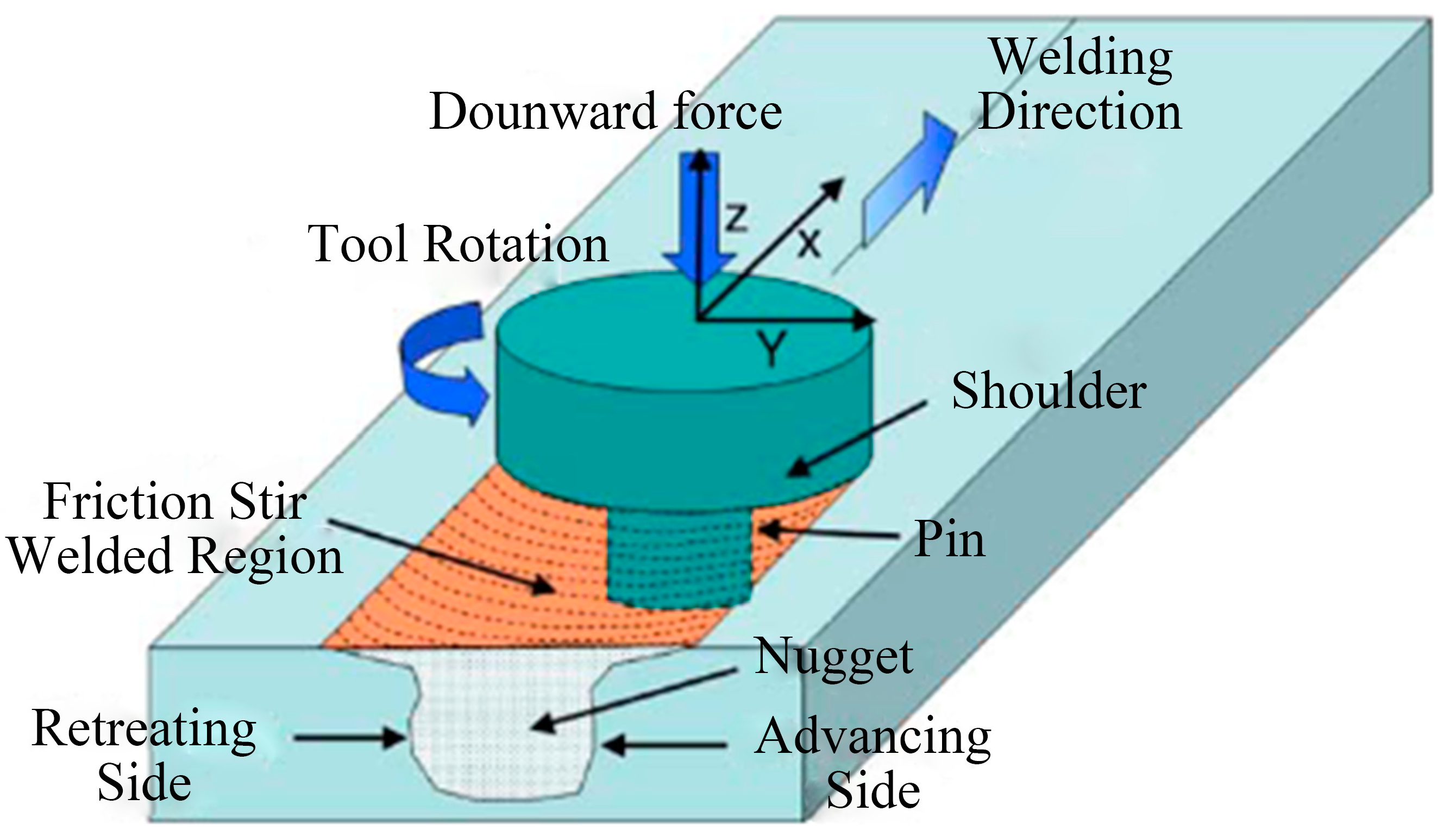
2.1. Friction Stir Welding
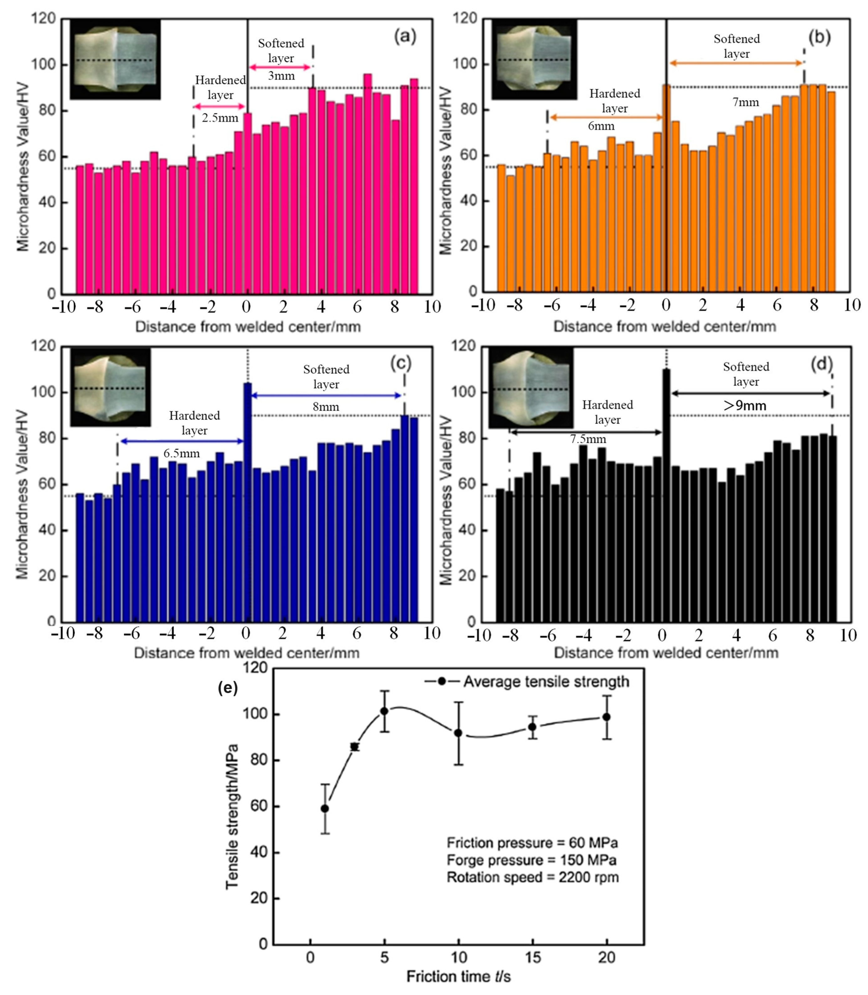
2.2. Friction Welding
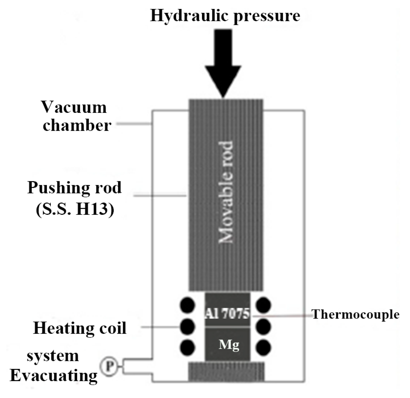
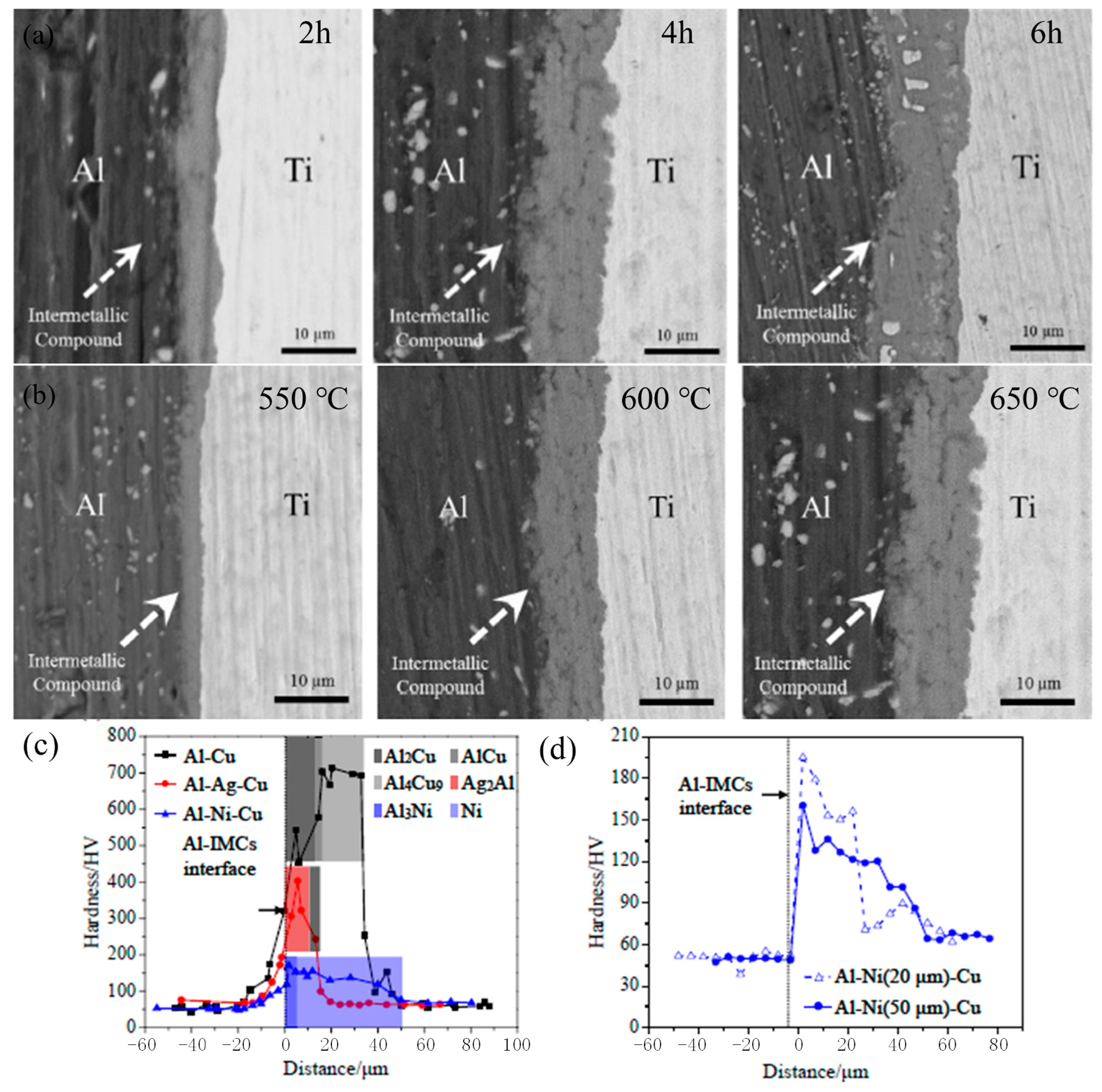
2.3. Diffusion Welding
2.4. Superplastic Solid-State Welding
2.5. Explosive Welding
2.6. Electromagnetic Pulse Welding
3. Plastic Deformation Strengthening
3.1. Physical Surface Modification
3.2. Large-Scale Plastic Deformation Technology
4. Summary
5. Conclusions
Author Contributions
Funding
Conflicts of Interest
References
- Dubourg, L.; Merati, A.; Jahazi, M. Process optimisation and mechanical properties of friction stir lap welds of 7075-T6 stringers on 2024-T3 skin. Mater. Des. 2010, 31, 3324–3330. [Google Scholar] [CrossRef]
- Lequeu, P.; Smith, K.P.; Danielou, A. Aluminum-Copper-Lithium Alloy 2050 Developed for Medium to Thick Plate. J. Mater. Eng. Perform. 2010, 19, 841–847. [Google Scholar] [CrossRef]
- Mathers, G. The Welding of Aluminium and Its Alloys; Woodhead Publishing Ltd.: Abington Hall, UK, 2002. [Google Scholar]
- Vargas, J.A.; Torres, J.E.; Pacheco, J.A.; Hernandez, R.J. Analysis of heat input effect on the mechanical properties of Al-6061-T6 alloy weld joints. Mater. Des. 2013, 52, 556–564. [Google Scholar] [CrossRef]
- Lu, H.; Shi, L.; Dong, H.; Li, S.; Guo, D.; Tao, C. Influence of flame rectification on mechanical properties of Al–Zn–Mg alloy. J. Alloys Compd. 2016, 689, 278–286. [Google Scholar] [CrossRef]
- Zhang, K.; Chen, J.; Ma, P.; Zhang, X. Effect of welding thermal cycle on microstructural evolution of Al–Zn–Mg–Cu alloy. Mater. Sci. Eng. A 2018, 717, 85–94. [Google Scholar] [CrossRef]
- Ma, T.; Den Ouden, G. Softening behaviour of Al–Zn–Mg alloys due to welding. Mater. Sci. Eng. A 1999, 266, 198–204. [Google Scholar] [CrossRef]
- Zhang, X.; Chen, J.; Zhang, K.; Chen, H. The softening effect of heat-treated strengthened Al–Zn–Mg alloy in welding process. Int. J. Mod. Phys. B 2017, 31, 1744039. [Google Scholar] [CrossRef]
- Wu, S.; Yu, X.; Zuo, R.; Zhang, W.; Xie, H.; Jiang, J. Porosity, element loss, and strength model on softening behavior of hybrid laser arc welded Al-Zn-Mg-Cu alloy with synchrotron radiation analysis. Weld. J. 2013, 92, 64–71. [Google Scholar]
- Wu, S.; Hu, Y.; Song, X.; Xue, Y.; Peng, J. On the microstructural and mechanical characterization of hybrid laser-welded Al-Zn-Mg-Cu alloys. J. Mater. Eng. Perform. 2015, 24, 1540–1550. [Google Scholar] [CrossRef]
- Ahn, J.; Chen, L.; He, E.; Davies, C.; Dear, J. Effect of filler metal feed rate and composition on microstructure and mechanical properties of fibre laser welded AA 2024-T3. J. Manuf. Process. 2017, 25, 26–36. [Google Scholar] [CrossRef]
- Chen, C.; Sun, G.; Zhao, Y.; Chen, F.; Zhang, H.; Liu, J. Microstructure and mechanical properties of 2A12 aluminum alloy welded joint through CMT double side welding. CIRP J. Manuf. Sci. Technol. 2022, 37, 258–266. [Google Scholar] [CrossRef]
- Bunaziv, I.; Akselsen, O.M.; Ren, X.; Nyhus, B.; Eriksson, M. Laser beam and laser-arc hybrid welding of aluminium alloys. Metals 2021, 11, 1150. [Google Scholar] [CrossRef]
- Xu, L.; Tian, Z.; Peng, Y.; Zhang, X. Comparison of MIG welding and laser-MIG welding of high strength aluminum alloy. Trans. China Weld. Inst. 2007, 2, 38–42. [Google Scholar]
- Kuo, T.; Lin, H. Effects of pulse level of Nd-YAG laser on tensile properties and formability of laser weldments in automotive aluminum alloys. Mater. Sci. Eng. A 2006, 416, 281–289. [Google Scholar] [CrossRef]
- Wang, H.; Cen, S. Research on microstructure and mechanical properties of CMT and MIG welded joints of A6N01 aluminum alloy. In Proceedings of the International Conference on Advanced Technologies and Applications of Modern Industry, Wuhan, China, 19–21 November 2021; p. 012051. [Google Scholar]
- Naing, T.H.; Muangjunburee, P. Metallurgical and mechanical characterization of MIG welded repair joints for 6082-T6 aluminum alloy with ER 4043 and ER 5356. Trans. Indian Inst. Met. 2022, 75, 1583–1593. [Google Scholar] [CrossRef]
- Zhong, S.; Han, S.; Chen, J.; Ren, J.; Zhou, Z.; Wen, F.; Qi, L.; Guan, R. Microstructure and properties of 7075 aluminum alloy welding joint using different filler metals. Mater. Today Commun. 2022, 31, 103260. [Google Scholar] [CrossRef]
- Luo, G.; Cheng, M.; Liu, C.; Li, S.; Wang, X.; Song, L. Improving mechanical properties of quasi-continuous-wave laser beam welded 7075 aluminum alloy through microstructural refinement and homogenization of the fusion zone. Opt. Laser Technol. 2022, 153, 108221. [Google Scholar] [CrossRef]
- Wang, J. Investigation on the Process and Microstructure Properties of the Double Wire MIG Welding for 7N01 High Strength Aluminum Alloy. Master’s Thesis, Shenyang Aerospace University, Shenyang, China, 2019. [Google Scholar]
- Zhang, L. Research on the Process of Thick 7A52 Aluminum Alloy by Laser-MIG Hybrid Welding. Master’s Thesis, Nanjing University of Science & Technology, Nanjing, China, 2018. [Google Scholar]
- Ko, Y.G.; Chaudry, U.M.; Hamad, K. Microstructure and mechanical properties of AA6061 alloy deformed by differential speed rolling. Mater. Lett. 2020, 259, 126870. [Google Scholar] [CrossRef]
- Yang, Q.; Zhou, Y.; Tan, Y.; Xiang, S.; Ma, M.; Zhao, F. Effects of microstructure, texture evolution and strengthening mechanisms on mechanical properties of 3003 aluminum alloy during cryogenic rolling. J. Alloys Compd. 2021, 884, 161135. [Google Scholar] [CrossRef]
- Wang, T.; Huang, Y.; Ma, Y.; Wu, L.; Yan, H.; Liu, C.; Liu, Y.; Liu, B.; Liu, W. Microstructure and mechanical properties of powder metallurgy 2024 aluminum alloy during cold rolling. J. Mater. Res. Technol. 2021, 15, 3337–3348. [Google Scholar] [CrossRef]
- Yu, P.; Wu, C.; Shi, L. Analysis and characterization of dynamic recrystallization and grain structure evolution in friction stir welding of aluminum plates. Acta Mater. 2021, 207, 116692. [Google Scholar] [CrossRef]
- Mehri, A.; Abdollah-zadeh, A.; Habibi, N.; Hajian, M.; Wang, J.T. The effects of rotational speed on microstructure and mechanical properties of friction stir-welded 7075-T6 thin sheet. J. Mater. Eng. Perform. 2020, 29, 2316–2323. [Google Scholar] [CrossRef]
- Won, S.; Seo, B.; Park, J.M.; Kim, H.K.; Song, K.H.; Min, S.-H.; Ha, T.K.; Park, K. Corrosion behaviors of friction welded dissimilar aluminum alloys. Mater. Charact. 2018, 144, 652–660. [Google Scholar] [CrossRef]
- Meisnar, M.; Baker, S.; Bennett, J.; Bernad, A.; Mostafa, A.; Resch, S.; Fernandes, N.; Norman, A. Microstructural characterisation of rotary friction welded AA6082 and Ti-6Al-4V dissimilar joints. Mater. Des. 2017, 132, 188–197. [Google Scholar] [CrossRef]
- Habisch, S.; Böhme, M.; Peter, S.; Grund, T.; Mayr, P. The effect of interlayer materials on the joint properties of diffusion-bonded aluminium and magnesium. Metals 2018, 8, 138. [Google Scholar] [CrossRef]
- Golden Renjith Nimal, R.; Sivakumar, M.; Arungalai Vendan, S.; Esakkimuthu, G. Effect of mechanical and metallurgical analysis of magnesium and aluminium alloys using diffusion bonding. In Proceedings of the Advanced Manufacturing and Materials Science, Kochi, India, 15–16 January 2018; pp. 395–401. [Google Scholar]
- Wu, H. Influence of process variables on press bonding of superplastic 8090 Al–Li alloy. Mater. Sci. Eng. A 1999, 264, 194–200. [Google Scholar] [CrossRef]
- Pilling, J.; Ridley, N. Solid state bonding of superplastic AA 7475. Mater. Sci. Technol. 1987, 3, 353–359. [Google Scholar] [CrossRef]
- Findik, F. Recent developments in explosive welding. Mater. Des. 2011, 32, 1081–1093. [Google Scholar] [CrossRef]
- Göbel, G.; Kaspar, J.; Herrmannsdörfer, T.; Brenner, B.; Beyer, E. Insights into intermetallic phases on pulse welded dissimilar metal joints. In Proceedings of the 4th International Conference on High-Speed Forming, Columbus, OH, USA, 9–10 March 2010. [Google Scholar]
- Xie, S.; Xia, Z.; Ding, R.; Li, H.; Bowen, P. Microstructure and mechanical properties of two Al alloys welded by linear friction weld. Mater. Sci. Eng. A 2021, 816, 141261. [Google Scholar] [CrossRef]
- Chen, Y.; Jiang, Y.; Ding, H.; Zhao, J.; Li, J. Effects of friction-stir processing with water cooling on the properties of an Al–Zn–Mg–Cu alloy. Mater. Sci. Technol. 2018, 34, 153–160. [Google Scholar] [CrossRef]
- Wang, J.; Yang, J.; Zhang, J.; Dong, Z.; Fang, H.; Gang, T. A new weld shaping method with trailing impact rolling andtensile and fatigue properties for equal load-carrying capacity joints. Trans. China Weld. Inst. 2012, 11, 35–38. [Google Scholar]
- Wang, C.; Wan, Z.; Zhao, M. Effect of peening on property of welded joint of aluminum alloy. J. Harbin Inst. Technol. 2002, 34, 864–868. [Google Scholar]
- Fang, H.; Dong, Z.; Xu, W. Process of avoiding welding hot cracking of thin plate with trailing peening. Welding 2002, 3, 17–20. [Google Scholar]
- Xie, W.; Huang, T.; Yang, C.; Fan, C.; Lin, S.; Xu, W. Comparison of microstructure, mechanical properties, and corrosion behavior of Gas Metal Arc (GMA) and Ultrasonic-wave-assisted GMA (U-GMA) welded joints of Al–Zn–Mg alloy. J. Mater. Process. Technol. 2020, 277, 116470. [Google Scholar] [CrossRef]
- Zhang, L.; Li, X.; Nie, Z.; Huang, H.; Sun, J. Softening behavior of a new Al-Zn-Mg-Cu alloy due to TIG welding. J. Mater. Eng. Perform. 2016, 25, 1870–1879. [Google Scholar] [CrossRef]
- Li, S.; Xu, W.; Xiao, G.; Zhou, Z.; Su, F.; Feng, J. Effects of Sc on laser hot-wire welding performance of 7075 aluminum alloy. Mater. Res. Express. 2020, 7, 106506. [Google Scholar] [CrossRef]
- Selvamani, S.; Govindarajan, P.; Ajaymohan, M.; Hariharan, S.; Vigneshwar, M. Developing empirical relationship to predict maximum tensile strength on AA 7075 CMT welded Al alloy. In Proceedings of the 3rd International Conference on Materials and Manufacturing Engineering, Kancheepuram, India, 8–9 March 2018; p. 012060. [Google Scholar]
- Song, G.; Wang, Z.; Liu, Z.; Liu, L. Effect of partial rolling on the microstructure and mechanical properties of laser-TIG hybrid welded joints of 7075-T6 aluminum alloy. Int. J. Adv. Manuf. Technol. 2022, 121, 589–599. [Google Scholar] [CrossRef]
- Mishra, R.S.; Ma, Z. Friction stir welding and processing. Mater. Sci. Eng. R. 2005, 50, 1–78. [Google Scholar] [CrossRef]
- Prabha, K.A.; Putha, P.K.; Prasad, B.S. Effect of tool rotational speed on mechanical properties of aluminium alloy 5083 weldments in friction stir welding. Mater. Today Proc. 2018, 5, 18535–18543. [Google Scholar] [CrossRef]
- Trueba, L.; Torres, M.A.; Johannes, L.B.; Rybicki, D. Process optimization in the self-reacting friction stir welding of aluminum 6061-T6. Int. J. Mater. Form. 2018, 11, 559–570. [Google Scholar] [CrossRef]
- Rasaee, S.; Mirzaei, A.; Almasi, D.; Hayati, S. A comprehensive study of parameters effect on mechanical properties of butt friction stir welding in aluminium 5083 and copper. Trans. Indian Inst. Met. 2018, 71, 1553–1561. [Google Scholar] [CrossRef]
- Napitupulu, R.A.; Simanjuntak, S.L.; Manurung, C.; Hutabarat, C.; Sitompul, S.; Aoh, J. Friction stir welding of aluminium alloy 6061-t651. In Proceedings of the Tarumanagara International Conference on the Applications of Technology and Engineering, Jakarta, Indonesia, 22–23 November 2018; p. 012064. [Google Scholar]
- Srinivasan, R.; Ramesh, A.; Athithanambi, A. Effect of axial force on microstructure and mechanical properties of friction stir welded squeeze cast A413 aluminium alloy. Mater. Today Proc. 2018, 5, 13486–13494. [Google Scholar] [CrossRef]
- Sinhmar, S.; Dwivedi, D.K. A study on corrosion behavior of friction stir welded and tungsten inert gas welded AA2014 aluminium alloy. Corros. Sci. 2018, 133, 25–35. [Google Scholar] [CrossRef]
- IbrahimMarhoon, I.; Al-Kamal, A.K.; Abdulrehman, M.A. Studying the mechanical properties for 5086 aluminum alloy welded plates by friction stir welding (FSW). In Proceedings of the 1st International Conference on Materials Engineering and Science, Istanbul Aydin University, Istanbul, Turkey, 8–9 August 2018; p. 012084. [Google Scholar]
- Huang, C.; Mao, Y.; Chen, Y.; Liu, Q.; Ke, L. Effect of welding parameters on microstructure and mechanical properties of friction stir welded joints of 2060 aluminum lithium alloy. Int. J. Adv. Manuf. Technol. 2015, 81, 1419–1431. [Google Scholar]
- Zhang, J.; Feng, X.; Gao, J.; Huang, H.; Ma, Z.; Guo, L. Effects of welding parameters and post-heat treatment on mechanical properties of friction stir welded AA219S-T8 Al-Li alloy. J. Mater. Sci. Technol. 2018, 34, 219–227. [Google Scholar] [CrossRef]
- Rajakumar, S.; Balasubramanian, V. Establishing relationships between mechanical properties of aluminium alloys and optimised friction stir welding process parameters. Mater. Des. 2012, 40, 17–35. [Google Scholar] [CrossRef]
- Gadakh, V.; Kumar, A. Modelling and microstructure of friction stir welds of AA2014 alloy: Different tool pin profiles. Mater. Today Proc. 2018, 5, 7447–7456. [Google Scholar] [CrossRef]
- Ma, H.; Wang, Y.; Tian, Z.; Xiong, L.; Zhang, Y. Gap-tolerance control for friction stir butt welding of 2A14 aluminium alloy. Measurement 2019, 148, 106915. [Google Scholar] [CrossRef]
- Palanivel, R.; Laubscher, R.; Vigneshwaran, S.; Dinaharan, I. Prediction and optimization of the mechanical properties of dissimilar friction stir welding of aluminum alloys using design of experiments. Proc. Inst. Mech. Eng. Part B 2018, 232, 1384–1394. [Google Scholar] [CrossRef]
- Singh, A.; Kumar, V.; Grover, N.K. Influence of tool pin profiles on friction stir welding with a gap for AA6082-T6 aluminium alloy. Mater. Res. Express. 2019, 6, 086543. [Google Scholar] [CrossRef]
- Khan, N.Z.; Siddiquee, A.N.; Khan, Z.A.; Ubaid, M.; Bajaj, D.; Atif, M.; Khan, A. Microstructure evolution of friction stir welded dissimilar aerospace aluminium alloys. In Proceedings of the 1st International Conference on Contemporary Research in Mechanical Engineering with Focus on Materials and Manufacturing Lucknow, India, 6–7 April 2018; p. 012002. [Google Scholar]
- Sunnapu, C.; Kolli, M. Tool shoulder and pin geometry’s effect on friction stir welding: A study of literature. Mater. Today Proc. 2021, 39, 1565–1569. [Google Scholar] [CrossRef]
- Rao, C.V.; Reddy, G.M.; Rao, K.S. Influence of tool pin profile on microstructure and corrosion behaviour of AA2219 Al–Cu alloy friction stir weld nuggets. Def. Technol. 2015, 11, 197–208. [Google Scholar]
- Lu, X.; Meng, X.; Ma, C.; Sun, S.; Liang, S.Y. Microstructure and mechanical properties of FSW medium thickness 2219 aluminum alloy. Proc. Inst. Mech. Eng. Part C 2022, 236, 9072–9080. [Google Scholar] [CrossRef]
- Fang, Y.; Zhang, H. Microstructure and mechanical properties for thick plate 5083 aluminum alloy friction stir welding joint along the thickness direction. J. Mech. Eng. 2022, 58, 94–101. [Google Scholar]
- Shen, H.; Yang, X.; Li, D.; Cui, L. Microstructures and mechanical properties of 6061-T6 aluminum alloy welded by stationary shoulder friction stir welding process. Trans. China Weld. Inst. 2016, 37, 119–123. [Google Scholar]
- Anil Kumar, H.; Venkata Ramana, V.; Pawar, M. Experimental study on dissimilar friction stir welding of aluminium alloys (5083-H111 and 6082-T6) to investigate the mechanical properties. In Proceedings of the International Conference on Recent Advances in Materials, Mechanical and Civil Engineering, Hyderabad, India, 1–2 June 2017; p. 012076. [Google Scholar]
- Chen, Y.; Li, H.; Wang, X.; Ding, H.; Zhang, F. A comparative investigation on conventional and stationary shoulder friction stir welding of Al-7075 butt-lap structure. Metals 2019, 9, 1264. [Google Scholar] [CrossRef]
- Bocchi, S.; D’Urso, G.; Giardini, C. The effect of heat generated on mechanical properties of friction stir welded aluminum alloys. Int. J. Adv. Manuf. Technol. 2021, 112, 1513–1528. [Google Scholar] [CrossRef]
- Peng, G.; Yan, Q.; Hu, J.; Chen, P.; Chen, Z.; Zhang, T. Effect of forced air cooling on the microstructures, tensile strength, and hardness distribution of dissimilar friction stir welded AA5A06-AA6061 joints. Metals 2019, 9, 304. [Google Scholar] [CrossRef]
- Singh, A.; Kumar, V.; Grover, N.K. A study of microstructure and mechanical properties of friction stir welding aluminium alloy AA6082 with Zn interlayer. Mater. Res. Express. 2019, 6, 116596. [Google Scholar] [CrossRef]
- Mokabberi, S.; Movahedi, M.; Kokabi, A. Effect of interlayers on softening of aluminum friction stir welds. Mater. Sci. Eng. A 2018, 727, 1–10. [Google Scholar] [CrossRef]
- Yadav, D.; Bauri, R.; Chawake, N. Fabrication of Al-Zn solid solution via friction stir processing. Mater. Charact. 2018, 136, 221–228. [Google Scholar] [CrossRef]
- Bocchi, S.; D’Urso, G.; Giardini, C. Preliminary study of the mechanical characteristics implementation of friction stir welded AA2024 joints by adding pure copper. Mater. Res. Proc. 2023, 25, 213–220. [Google Scholar]
- Fu, B.; Qin, G.; Li, F.; Meng, X.; Zhang, J.; Wu, C. Friction stir welding process of dissimilar metals of 6061-T6 aluminum alloy to AZ31B magnesium alloy. J. Mater. Process. Technol. 2015, 218, 38–47. [Google Scholar] [CrossRef]
- Zhao, Y.; Jiang, S.; Yang, S.; Lu, Z.; Yan, K. Influence of cooling conditions on joint properties and microstructures of aluminum and magnesium dissimilar alloys by friction stir welding. Int. J. Adv. Manuf. Technol. 2016, 83, 673–679. [Google Scholar] [CrossRef]
- Firouzdor, V.; Kou, S. Al-to-Mg friction stir welding: Effect of material position, travel speed, and rotation speed. Metall. Mater. Trans. A 2010, 41, 2914–2935. [Google Scholar] [CrossRef]
- Liu, Z.; Ji, S.; Meng, X. Joining of magnesium and aluminum alloys via ultrasonic assisted friction stir welding at low temperature. Int. J. Adv. Manuf. Technol. 2018, 97, 4127–4136. [Google Scholar] [CrossRef]
- Luo, L.; Yang, B.; Quan, Q.; Yang, X.; Liu, X.; Wang, J. Effect of rapid cooling on the microstructure and properties of fine-grained 7075 aluminium alloy under friction stir welding. Mater. Res. Express. 2022, 9, 056521. [Google Scholar] [CrossRef]
- Pinheiro, M.A.; Bracarense, A.Q. Influence of initial contact geometry on mechanical properties in friction welding of dissimilar materials aluminum 6351 T6 and SAE 1020 steel. Adv. Mater. Sci. Eng. 2019, 2019, 1759484. [Google Scholar] [CrossRef]
- Fuji, A.; Kimura, M.; North, T.; Ameyama, K.; Aki, M. Mechanical properties of titanium-5083 aluminium alloy friction joints. Mater. Sci. Technol. 1997, 13, 673–678. [Google Scholar] [CrossRef]
- Fukumoto, S.; Tsubakino, H.; Okita, K.; Aritoshi, M.; Tomita, T. Friction welding process of 5052 aluminium alloy to 304 stainless steel. Mater. Sci. Technol. 1999, 15, 1080–1086. [Google Scholar] [CrossRef]
- Akca, E.; Gürsel, A. Solid state welding and application in aeronautical industry. Period. Eng. Nat. Sci. 2016, 4, 1–8. [Google Scholar] [CrossRef]
- Liang, Z.; Qin, G.; Geng, P.; Yang, F.; Meng, X. Continuous drive friction welding of 5A33 Al alloy to AZ31B Mg alloy. J. Manuf. Process. 2017, 25, 153–162. [Google Scholar] [CrossRef]
- Buffa, G.; Cammalleri, M.; Campanella, D.; La Commare, U.; Fratini, L. Linear friction welding of dissimilar AA6082 and AA2011 aluminum alloys: Microstructural characterization and design guidelines. Int. J. Mater. Form. 2017, 10, 307–315. [Google Scholar] [CrossRef]
- Bouarroudj, E.-O.; Chikh, S.; Abdi, S.; Miroud, D. Thermal analysis during a rotational friction welding. Appl. Therm. Eng. 2017, 110, 1543–1553. [Google Scholar] [CrossRef]
- Selvamani, S.; Palanikumar, K. Optimizing the friction welding parameters to attain maximum tensile strength in AISI 1035 grade carbon steel rods. Measurement 2014, 53, 10–21. [Google Scholar] [CrossRef]
- Meengam, C.; Chainarong, S.; Muangjunburee, P. Friction welding of semi-solid metal 7075 aluminum alloy. Mater. Today Proc. 2017, 4, 1303–1311. [Google Scholar] [CrossRef]
- Li, X.; Li, J.; Liao, Z.; Jin, F.; Xiong, J.; Zhang, F. Effect of rotation speed on friction behavior and radially non-uniform local mechanical properties of AA6061-T6 rotary friction welded joint. J. Adhes. Sci. Technol. 2018, 32, 1987–2006. [Google Scholar] [CrossRef]
- Wan, L.; Huang, Y. Friction welding of AA6061 to AISI 316L steel: Characteristic analysis and novel design equipment. Int. J. Adv. Manuf. Technol. 2018, 95, 4117–4128. [Google Scholar] [CrossRef]
- Guo, W.; You, G.; Yuan, G.; Zhang, X. Microstructure and mechanical properties of dissimilar inertia friction welding of 7A04 aluminum alloy to AZ31 magnesium alloy. J. Alloys Compd. 2017, 695, 3267–3277. [Google Scholar] [CrossRef]
- Kimura, M.; Inui, Y.; Kusaka, M.; Kaizu, K. Effects of friction welding conditions on tensile strength of friction welded joint between 5052 Al alloy and pure copper. Mech. Eng. J. 2018, 5, 17-00398. [Google Scholar] [CrossRef]
- Alex, A.J.; Padmanaban, R.; Govindaraju, M. Effect of Fe particles on the microstructural evolution and mechanical properties of friction welded Al-Cu components. Aust. J. Mech. Eng. 2022, 20, 855–865. [Google Scholar] [CrossRef]
- Geng, P.; Qin, G.; Zhou, J.; Li, C. Parametric optimization and microstructural characterization of friction welded aeronautic aluminum alloy 2024. Trans. Nonferrous Met. Soc. China 2019, 29, 2483–2495. [Google Scholar] [CrossRef]
- Musin, F.F.; Medvedev, A.Y.; Bolshakov, B.O. Linear Friction Welding of a Commercial Aluminum Alloy. Mater. Sci. Forum 2016, 870, 608–613. [Google Scholar] [CrossRef]
- Selvamani, S.T.; Divagar, S.; Vigneshwar, M. Optimizing the Friction Welding Process Parameter to Obtain the Maximum Tensile Strength in AA 2024 Grade High Strength Aluminum Alloy Joints. Int. J. Eng. Res. Afr. 2016, 25, 11–19. [Google Scholar] [CrossRef]
- Assari, A.H.; Eghbali, B. Solid state diffusion bonding characteristics at the interfaces of Ti and Al layers. J. Alloys Compd. 2019, 773, 50–58. [Google Scholar] [CrossRef]
- Afghahi, S.S.S.; Jafarian, M.; Paidar, M.; Jafarian, M. Diffusion bonding of Al 7075 and Mg AZ31 alloys: Process parameters, microstructural analysis and mechanical properties. Trans. Nonferrous Met. Soc. China 2016, 26, 1843–1851. [Google Scholar] [CrossRef]
- Ma, Y.; Wu, L.; Long, L.; Liu, W.; Liu, C. Microstructure and mechanic property of Mg/Al joints obtained by vacuum diffusion bonding. Trans. Nonferrous Met. Soc. China 2017, 27, 1083–1090. [Google Scholar]
- Varmazyar, J.; Khodaei, M. Diffusion bonding of aluminum-magnesium using cold rolled copper interlayer. J. Alloys Compd. 2019, 773, 838–843. [Google Scholar] [CrossRef]
- Azizi, A.; Alimardan, H. Effect of welding temperature and duration on properties of 7075 Al to AZ31B Mg diffusion bonded joint. Trans. Nonferrous Met. Soc. China 2016, 26, 85–92. [Google Scholar] [CrossRef]
- Kundu, S.; Ghosh, M.; Laik, A.; Bhanumurthy, K.; Kale, G.; Chatterjee, S. Diffusion bonding of commercially pure titanium to 304 stainless steel using copper interlayer. Mater. Sci. Eng. A 2005, 407, 154–160. [Google Scholar] [CrossRef]
- Rajakumar, S.; Balasubramanian, V. Diffusion bonding of titanium and AA 7075 aluminum alloy dissimilar joints—Process modeling and optimization using desirability approach. Int. J. Adv. Manuf. Technol. 2016, 86, 1095–1112. [Google Scholar] [CrossRef]
- Xiong, J.; Peng, Y.; Zhang, H.; Li, J.; Zhang, F. Microstructure and mechanical properties of Al-Cu joints diffusion-bonded with Ni or Ag interlayer. Vacuum 2018, 147, 187–193. [Google Scholar] [CrossRef]
- Liu, L.; Zhao, L.; Xu, R. Effect of interlayer composition on the microstructure and strength of diffusion bonded Mg/Al joint. Mater. Des. 2009, 30, 4548–4551. [Google Scholar] [CrossRef]
- Teng, Q.; Li, X.; Wei, Q. Diffusion bonding of Al 6061 and Cu by hot isostatic pressing. J. Wuhan Univ. Technol. 2020, 35, 183–191. [Google Scholar] [CrossRef]
- Elsa, M.; Khorram, A.; Ojo, O.; Paidar, M. Effect of bonding pressure on microstructure and mechanical properties of aluminium/copper diffusion-bonded joint. Sadhana 2019, 44, 126. [Google Scholar] [CrossRef]
- Huang, Y.; Ma, L. Supperplastic forming with diffusion boding (SPF/DB) of aluminum alloys. Mater. Sci. Prog. 1988, 2, 11–17. [Google Scholar]
- Song, X.; Du, S.; Jiang, Z. Research development of superplastic solid-state welding. New Technol. New Process. 2013, 3, 99–101. [Google Scholar]
- Mofidi, H.; Nishihara, T. Effect of friction stir processing on superplastic behavior of Zn-22Al alloy. In Proceedings of the 1st International Joint Symposium on Joining and Welding, Osaka, Japan, 6–8 November 2013; pp. 383–387. [Google Scholar]
- Wu, H.; Lee, S.; You, Y. Genuine solid-state bonding characteristics of superplastic Al-alloys. J. Mater. Process. Technol. 2002, 122, 226–231. [Google Scholar] [CrossRef]
- Wu, H.; Lee, S. Effect of bonding variables on bonding mechanisms in press bonding superplastic 8090 aluminium alloy. Mater. Sci. Technol. 2001, 17, 906–911. [Google Scholar] [CrossRef]
- Liu, J.; Chakrabarti, D. Grain structure and microtexture evolution during superplastic forming of a high strength Al Zn Mg Cu alloy. Acta Mater. 1996, 44, 4647–4661. [Google Scholar] [CrossRef]
- Huang, Y.; Ridley, N.; Humphreys, F.; Cui, J.-Z. Diffusion bonding of superplastic 7075 aluminium alloy. Mater. Sci. Eng. A 1999, 266, 295–302. [Google Scholar] [CrossRef]
- Wilkinson, D.; Caceres, C. An evaluation of available data for strain-enhanced grain growth during superplastic flow. J. Mater. Sci. Lett. 1984, 3, 395–399. [Google Scholar] [CrossRef]
- Lavernia, E.J.; Grant, N.J. Aluminium-lithium alloys. J. Mater. Sci. 1987, 22, 1521–1529. [Google Scholar] [CrossRef]
- Garmong, G.; Paton, N.; Argon, A.S. Attainment of full interfacial contact during diffusion bonding. Metall. Trans. A 1975, 6, 1269–1279. [Google Scholar] [CrossRef]
- Li, S. Research on Superplastic Forming/Diffusion Bonding of 5A70 Aluminum Alloy. Master Thesis, University of Science and Technology Beijing, Beijing, China, 2019. [Google Scholar]
- Huang, Y.; Cui, J.; Ma, L. Diffusion bonding of superplastic 7075 aluminum alloy. In Proceedings of the Symposium at the 1990 Spring Meeting of the Materials Research Society, Superplasticity in Metals, Ceramics, and Intermetallics, San Francisco, CA, USA, 16–20 April 1990. [Google Scholar]
- Zhang, J.; Zhou, Y.; Niu, J. Superplastic forming and diffusion bonding of Al-6Mg alloy. J. Mater. Eng. 1995, 4, 35–37. [Google Scholar]
- Jiang, S.; Jia, Y.; Lu, Z.; Shi, C.; Zhang, K. Superplastic forming/diffusion bonding without interlayer of 5A90 Al-Li alloy hollow double-layer structure. J. Mater. Eng. Perform. 2017, 26, 4265–4273. [Google Scholar] [CrossRef]
- Li, Y.; Wang, H.; Niu, T.; Zhang, H.; Yuan, M. Study on SPF/DB Technology for Two-Sheet Hollow Structure of 1420 Al-Li Alloy. Metals 2022, 12, 389. [Google Scholar] [CrossRef]
- Gao, Y.; Nakata, K.; Nagatsuka, K.; Liu, F.C.; Liao, J. Interface microstructural control by probe length adjustment in friction stir welding of titanium and steel lap joint. Mater. Des. 2015, 65, 17–23. [Google Scholar] [CrossRef]
- Guo, X.; Tao, J.; Yuan, Z.; Zhang, L.; Sun, X. Investigation on interface and performance of explosive welded SS316L/Al clad tube. Rare Metal Mat. Eng. 2012, 41, 4. [Google Scholar]
- Honarpisheh, M.; Asemabadi, M.; Sedighi, M. Investigation of annealing treatment on the interfacial properties of explosive-welded Al/Cu/Al multilayer. Mater. Des. 2012, 37, 122–127. [Google Scholar] [CrossRef]
- Zhang, T.; Wang, W.; Yuan, X.; Liu, R.; Xie, R. Interface Bonding Mechanism of Mg/Al Alloy Explosive Welded. J. Mech. Eng. 2016, 52, 7. [Google Scholar] [CrossRef]
- Wang, J.; Deng, G.; Hou, F. Experimental studies on explosive welding of magnesium alloy(AZ31)/aluminum alloy(7A52) composite joints. Dev. Appl. Mater. 2011, 26, 5. [Google Scholar]
- Wang, J.; Zhang, Y.; Wang, Y.; Zhu, X. Explosive mass-bonding property in aluminum alloy-steel explosive welding. J. Mater. Eng. 2009, 2, 443–447. [Google Scholar]
- Wang, J.; Zhu, X.; Liu, R. Influencing factors of wave parameters for the explosive welded bonding interface. Chin. J. Eng. 2008, 30, 636–639. [Google Scholar]
- Chi, L.; Huang, Y.; Xu, H.; Gu, L.; Zhang, Y.; Ran, Y.; Wu, J. Analysis on interface characteristics and metal particle distributions in electromagnetic pulse welding with aluminum to steel. Trans. China Weld. Inst. 2023, 44, 36–43. [Google Scholar]
- Xu, Z. Numerical and Experimental Investigation on 3A21 Aluminum Alloy and 20 Steel Tube Magnetic Pulse Welding. Master’s Thesis, Harbin Institute of Technology, Harbin, China, 2013. [Google Scholar]
- Lee, K.J.; Kumai, S.; Arai, T.; Aizawa, T. Interfacial microstructure and strength of steel/aluminum alloy lap joint fabricated by magnetic pressure seam welding. Mater. Sci. Eng. A 2007, 471, 95–101. [Google Scholar] [CrossRef]
- Nassiri, A.; Chini, G.; Kinsey, B. Spatial stability analysis of emergent wavy interfacial patterns in magnetic pulsed welding. CIRP Ann.-Manuf. Technol. 2014, 63, 245–248. [Google Scholar] [CrossRef]
- Zhang, Y.; Babu, S.S.; Prothe, C.; Blakely, M.; Kwasegroch, J.; Laha, M.; Daehn, G.S. Application of high velocity impact welding at varied different length scales. J. Mater. Process. Technol. 2011, 211, 944–952. [Google Scholar] [CrossRef]
- Abdulstaar, M.A.; Al-Fadhalah, K.J.; Wagner, L. Microstructural variation through weld thickness and mechanical properties of peened friction stir welded 6061 aluminum alloy joints. Mater. Charact. 2017, 126, 64–73. [Google Scholar] [CrossRef]
- Sun, G.; Fang, X.; Tong, Z.; Ni, Z.; Lu, Y. Effect of laser shock peening on aluminium alloy laser-welds. Surf. Eng. 2016, 32, 943–948. [Google Scholar] [CrossRef]
- Liu, P.; Sun, S.; Xu, S.; Li, Y.; Ren, G. Microstructure and properties in the weld surface of friction stir welded 7050-T7451 aluminium alloys by laser shock peening. Vacuum 2018, 152, 25–29. [Google Scholar] [CrossRef]
- Chao, C.; Furong, C.; Huijing, Z. Surface nanocrystallization of 7A52 aluminum alloy welded joint by aging and ultrasonic impact compound treatment. Rare Met. Mat. Eng. 2018, 47, 2637–2641. [Google Scholar] [CrossRef]
- He, Y.; Wang, D.; Wang, Y.; Zhang, H. Correction of buckling distortion by ultrasonic shot peening treatment for 5A06 aluminum alloy welded structure. Trans. Nonferrous Met. Soc. China 2016, 26, 1531–1537. [Google Scholar] [CrossRef]
- Lu, J.; Luo, K.; Zhang, Y.; Cui, C.; Sun, G.; Zhou, J.; Zhang, L.; You, J.; Chen, K.; Zhong, J. Grain refinement of LY2 aluminum alloy induced by ultra-high plastic strain during multiple laser shock processing impacts. Acta Mater. 2010, 58, 3984–3994. [Google Scholar] [CrossRef]
- Xie, R.; Qiu, X.; Chen, F.; Shi, Z. Surface nanocrystallization of 7A52 aluminum alloy welded joint using ultrasonic impact treatment. Trans. China Weld. Inst. 2014, 35, 35–38. [Google Scholar]
- Chen, F.; Liu, C. Improving the properties of laser-welded Al–Zn–Mg–Cu alloy joints by aging and double-sided ultrasonic impact compound treatment. Materials 2021, 14, 2742. [Google Scholar] [CrossRef]
- Utne, S.C. Fatigue of Welded AA6082 Alloys-Effects of PWHT and Shot Peening. Master’s Thesis, Norwegian University of Science and Technology, Trondheim, Norway, 2013. [Google Scholar]
- Živković, D.; Anzulović, B. The fatigue of 5083 aluminium alloy welds with the shot-peened crater hot-cracks. Mater. Des. 2005, 26, 247–250. [Google Scholar] [CrossRef]
- Yang, J.; Wang, J.; Dong, Z.; Fang, H.; Zhou, L. Influence of weld shaping with trailing impact rolling on hardness and residual stress of under-matched equal load-carrying joint. Trans. China Weld. Inst. 2013, 34, 37–40. [Google Scholar]
- Chun, S. Investigation on fatigue Performance and Life Extension Mechanism of Aluminium Alloy Weldments Subjected to Warm Laser Peening. Master’s Thesis, Jiangsu University, Zhenjiang, China, 2017. [Google Scholar]
- Chen, F.; Liu, C. Improving the low-cycle fatigue properties of laser-welded Al–Zn–Mg–Cu alloy joints using double-sided ultrasonic impact treatment. Mater. Res. Express. 2021, 8, 096509. [Google Scholar] [CrossRef]
- Liu, W.; Tian, X.; Zhang, X. A new method for prevention of weld hot cracking. Trans. China Weld. Inst. 1995, 16, 106–111. [Google Scholar]
- Fan, C.; Fang, H.; Tian, Y.; Li, M. Influence on metallographic structure and mechanical properties of LY12CZ welded jointed with weld with trailing impactive rolling. J. Mater. Eng. 2004, 10, 24–28. [Google Scholar]
- Li, J.; Yang, J.; Lu, H.; Weng, L.; Fang, H. Controlling welding distortion of aluminum alloythin plates with rotating extrusion. Mater. Sci. Technol. 2010, 20, 293–296. [Google Scholar]
- Peng, Y.; Tian, X.; Zhong, G. Moire fringe simulation and experiment of synchronous rolling for preventing welding hot crack of aluminum alloy. Phys. Exam. Test. 1995, 2, 8–11. [Google Scholar]
- Cozzolino, L.D.; Coules, H.E.; Colegrove, P.A.; Wen, S. Investigation of post-weld rolling methods to reduce residual stress and distortion. J. Mater. Process. Technol. 2017, 247, 243–256. [Google Scholar] [CrossRef]
- Liu, W.; Tian, X.; Zhang, X.; Yu, Z. An investigation on improving mechanical properties of LY12CZ welded joints by synchronous rolling the weld. Met. Sci. Technol. 1992, 11, 114–119. [Google Scholar]
- Liu, W.; Tian, X.; Zhang, X. Preventing weld hot cracking by synchronous rolling during welding. Weld. J. 1996, 75, 297s. [Google Scholar]
- Zhao, Z.; Li, J.; Li, M. Process optimization on TIG welding of LY12CZ aluminum alloy with hammering and rolling technique. Rare Metal Mat. Eng. 2008, 37, 525–529. [Google Scholar]
- Ozaki, H.; Hayashi, S.; Kutsuna, M. Laser roll welding of dissimilar metal joint of titanium to aluminium alloy. Weld. Int. 2009, 23, 501–509. [Google Scholar] [CrossRef]
- Kurkin, S.; Anufriev, V. Preventing distortion of welded thin-walled members of AMg 6 and 1201 aluminium alloys by rolling the weld with a roller behind the welding arc. Weld. Prod. 1984, 31, 52–55. [Google Scholar]
- Wang, Z.; Zhang, Z.; Lang, Q.; Song, G.; Liu, L. Microstructure evolution and deformation behavior of TIG welded 7075-T6 aluminum alloy followed by partial hot rolling. J. Manuf. Process. 2023, 94, 524–538. [Google Scholar] [CrossRef]
- Du, C.; Pan, Q.; Chen, S.; Tian, S. Effect of rolling on the microstructure and mechanical properties of 6061-T6 DS-FSW plate. Mater. Sci. Eng. A 2020, 772, 138692. [Google Scholar] [CrossRef]
- Jin, Y.; Wu, Y.; Wang, X.; Guo, T. Effect of rolling on friction stir welded joints of aluminumalloy. Trans. China Weld. Inst. 2019, 40, 50–54. [Google Scholar]
- Hao, Z.; Li, X.; Li, Y.; Liu, P. Effect of multiple rotating rolling on the surface of friction stir weld of aluminum alloy. Trans. China Weld. Inst. 2017, 38, 125–128. [Google Scholar]
- Cheng, J.; Zhang, Z.; Dong, X.; Song, G.; Liu, L. A novel post-weld composite treatment process for improving the mechanical properties of AA 6061-T6 aluminum alloy welded joints. J. Manuf. Process. 2022, 82, 15–22. [Google Scholar] [CrossRef]
- Casalino, G.; El Mehtedi, M.; Forcellese, A.; Simoncini, M. Effect of cold rolling on the mechanical properties and formability of FSWed sheets in AA5754-H114. Metals 2018, 8, 223. [Google Scholar] [CrossRef]
- Wang, Z.; Zhang, Z.; Cheng, J.; Song, G.; Liu, L. Simultaneously increased strength and plasticity of TIG-welded 7075-T6 aluminum alloy joints via a novel post-weld composite treatment process. J. Mater. Res. Technol. 2023, 26, 542–555. [Google Scholar] [CrossRef]
- Cheng, J.; Song, G.; Zhang, Z.; Khan, M.S.; Dong, X.; Liu, L. Investigating the multiscale effects of a novel post–weld composite processing treatment on minimizing weld softening in AA6061-T6 Al–alloy. J. Mater. Res. Technol. 2022, 20, 4392–4408. [Google Scholar] [CrossRef]
- Gabrielli, F.; Forcellese, A.; El Mehtedi, M.; Simoncini, M. Mechanical properties and formability of cold rolled friction stir welded sheets in AA5754 for automotive applications. In Proceedings of the 17th International Conference on Sheet Metal, University Palermo, Palermo, Italy, 10–12 April 2017; pp. 245–250. [Google Scholar]
- Baisukhan, A.; Nakkiew, W. Sequential effects of deep rolling and post-weld heat treatment on surface integrity of AA7075-T651 aluminum alloy friction stir welding. Materials 2019, 12, 3510. [Google Scholar] [CrossRef]
- Zhang, H.; Zhao, X.; Liu, Y. Effect of high frequency impacting and rolling on fatigue crack growth of 2A12 aluminum alloy welded joint. Int. J. Fatigue 2021, 147, 106172. [Google Scholar] [CrossRef]
- Zhang, H.; Wang, X.; Wang, G.; Zhang, Y. Hybrid direct manufacturing method of metallic parts using deposition and micro continuous rolling. Rapid Prototyp. J. 2013, 19, 387–394. [Google Scholar] [CrossRef]
- Zhou, K.; Wang, S.; Zhang, H.; Wang, G.; Lai, X.; Wang, B. Effect of micro-casting and forging on microstructure and properties of 5A56 aluminum alloy produced by arc additive manufacturing. Hot Work. Technol. 2021. [Google Scholar] [CrossRef]
- Vimal, K.; Srinivas, M.N.; Rajak, S. Wire arc additive manufacturing of aluminium alloys: A review. Mater. Today Proc. 2021, 41, 1139–1145. [Google Scholar] [CrossRef]
- Gu, J.; Ding, J.; Williams, S.W.; Gu, H.; Bai, J.; Zhai, Y.; Ma, P. The strengthening effect of inter-layer cold working and post-deposition heat treatment on the additively manufactured Al–6.3Cu alloy. Mater. Sci. Eng. A 2016, 651, 18–26. [Google Scholar] [CrossRef]
- Huang, J.; Wang, R.; Zhang, H.; Wang, G. Study on the Strengthening Effect of Interlayer Micro-rolling on Additively Manufactured Al–4.7 Si Alloy. In Proceedings of the 10th International Conference on Advanced Manufacturing, Zhuhai, China, 24 March–26 March 2023; p. 012108. [Google Scholar]
- Xie, R.; Chen, X.; Shi, Y.; Yang, C.; Chen, S.; Liu, H. Printing high-strength high-elongation aluminum alloy using commercial ER2319 welding wires through deformation-based additive manufacturing. Mater. Sci. Eng. A 2023, 868, 144773. [Google Scholar] [CrossRef]
- Gu, J.; Yang, S.; Gao, M.; Bai, J.; Zhai, Y.; Ding, J. Micropore evolution in additively manufactured aluminum alloys under heat treatment and inter-layer rolling. Mater. Des. 2020, 186, 108288. [Google Scholar] [CrossRef]
- Eimer, E.; Ganguly, S.; Czink, S.; Dietrich, S.; Chehab, B.; Ding, J.; Williams, S. Effect of inter layer cold work on 2024 aluminium alloy produced by wire directed energy deposition. Mater. Sci. Eng. A 2023, 145272. [Google Scholar] [CrossRef]
- Gu, J.; Wang, X.; Bai, J.; Ding, J.; Williams, S.; Zhai, Y.; Liu, K. Deformation microstructures and strengthening mechanisms for the wire+ arc additively manufactured Al-Mg4. 5Mn alloy with inter-layer rolling. Mater. Sci. Eng. A 2018, 712, 292–301. [Google Scholar] [CrossRef]


| Base Metal | Welding Method | UTS of BM (MPa) | Elongation of BM | UTS of Joint (MPa) | Elongation of Joint (%) | Joint Efficiency (Joint/BM, %) | Ref. |
|---|---|---|---|---|---|---|---|
| AA2024 | LBW | 463 | 14.9 | 364 | 2.4 | 78.6 | [11] |
| AA2A12 | CMT | 300 | 16 | 220 | 10.0 | 73.3 | [12] |
| AA2060 | LBW | 495 | 13.9 | 304.4 | 7.6 | 61.5 | [13] |
| AA2519 | MIG | 479 | 11.2 | 275 | 3.0 | 57.4 | [14] |
| AA6022 | LBW | 233 | 28.5 | 170 | 2.5 | 72.9 | [15] |
| AA6N01 | CMT | 309 | 12.6 | 215 | 10.6 | 69.6 | [16] |
| AA6082 | MIG | 310 | 6.0 | 178 | 4.7 | 57.4 | [17] |
| AA7075 | TIG | 578 | 12.2 | 300 | 1.8 | 51.9 | [18] |
| AA7075 | LBW | 495 | 16.2 | 328 | 2.5 | 66.3 | [19] |
| AA7N01 | MIG | 406 | 16.3 | 289 | 4.7 | 71.2 | [20] |
| AA7A52 | Laser-MIG | 475 | 14.4 | 317 | 3.7 | 66.7 | [21] |
| Materials | UTS of BM (MPa) | El of BM (%) | UTS of Joint (MPa) | El of Joint (%) | Joint Efficiency (%) | Ref. |
|---|---|---|---|---|---|---|
| AA2A14 | 469 | 9.7 | 344 | 9.1 | 73.3 | [57] |
| AA2219 | 435 | 5.3 | 315 | 3.3 | 72.4 | [63] |
| AA5083 | 304 | 23.1 | 303 | 19.0 | 99.6 | [64] |
| AA6061 | 331 | 11.7 | 237 | 5.2 | 71.6 | [65] |
| AA6082 | 293 | 8.1 | 195 | 5.9 | 66.6 | [66] |
| AA7075 | 556 | 18.2 | 445 | 7.6 | 80.0 | [67] |
| Materials | FW Method | UTS of BM (MPa) | UTS of Joint (MPa) | Joint Efficiency (%) | Ref. |
|---|---|---|---|---|---|
| AA2024 | Continuous drive FW | 502 | 462 | 92.0 | [93] |
| AA2139 | Linear FW | 487 | 452 | 92.8 | [94] |
| AA2024 | Continuous drive FW | 450 | 390 | 86.7 | [95] |
| AA6061 | Rotary FW | 335 | 295 | 88.1 | [88] |
| Semi-solid metal 7075 | Rotary FW | / | 105 | / | [87] |
| AA5A33/AZ31B | Continuous drive FW | 352/271 | 101 | 37.3 | [83] |
| Materials | Welding Method | Physical Surface Modification | Test Conditions | Fatigue Properties of Welded Joint | Fatigue Properties of Treated Joint | Ref. |
|---|---|---|---|---|---|---|
| AA5083 | TIG | Shot peening | 105 cycles | 49 MPa | 78 MPa | [145] |
| 106 cycles | 28 MPa | 54 MPa | ||||
| AA6061-T6 | TIG | Warm laser peening | 172 MPa | 43,703 cycles | 75,683 cycles | [143] |
| 120 MPa | 87,850 cycles | 120,809 cycles | ||||
| AA6082.5-T6 | MIG | Shot peening | 106 cycles | 100 MPa | 138 MPa | [142] |
| AA7050-T7451 | FSW | Shock peening | 200 MPa | 10 × 105 cycles | 13 × 105 cycles | [136] |
| AA7075 | LBW | Ultrasonic impact | 2 × 10⁶ cycles | 48.6 MPa | 103.0 MPa | [146] |
| Deformation Technique | Purpose | Materials | Welding Method | Deformation Location | Ref. |
|---|---|---|---|---|---|
| Synchronous rolling during welding | Prevent hot cracks and improve mechanical performance | LY12CZ | TIG | Both sides of the weld, the weld beam | [147,152] |
| Synchronous rolling during welding | Prevent hot cracks | LY12CZ | Melt coating | Both sides of the weld | [150] |
| Synchronous rolling during welding | Prevent hot cracks | AA2024-T4 | TIG | Both sides of the weld | [153] |
| Welding with trailing impactive rolling | Control residual stress and hot cracks | LY12CZ | TIG | Weld bead and weld toe | [148] |
| Welding with rotating extrusion | Reduce residual distortion | AA2A12-T4 | TIG | Weld beam | [149] |
| Welding with trailing peening | Prevent hot cracks | AA2A12 | TIG | Both sides of the weld | [39] |
| Welding with hammering and rolling | Prevent hot cracks and welding distortion | LY12CZ | TIG | Weld beam | [154] |
| Laser roll welding | Produce Al/Steel dissimilar joints | AA5052 and SPCC steel | LBW | Overlap area | [154] |
| Laser roll welding | Produce Al/Ti dissimilar joints | AA5052 and H4600 Ti alloy | LBW | Overlap area | [155] |
| Welding with rolling | Prevent distortion | AMg6 Al alloy | TIG | Weld beam | [156] |
| Deformation Technique | Deformation Location | Materials | Welding Method | UTS of Welded Joints | UTS of Treated Joints | El of Welded Joints | El of Treated Joints | Ref. |
|---|---|---|---|---|---|---|---|---|
| Cold rolling | The whole joint | AA5754 | FSW | 220 | 270 | 12% | 5.8% | [162] |
| Cold rolling | The whole joint | AA5754 | FSW | 225 | 244 | / | / | [165] |
| Cold rolling | The whole joint | AA6061 | FSW | 229 | 369 | 20% | 6% | [158] |
| Cold rolling | Weld beam | AA7075 | Laser-TIG | 365 | 454 | 3.3% | 6.6% | [44] |
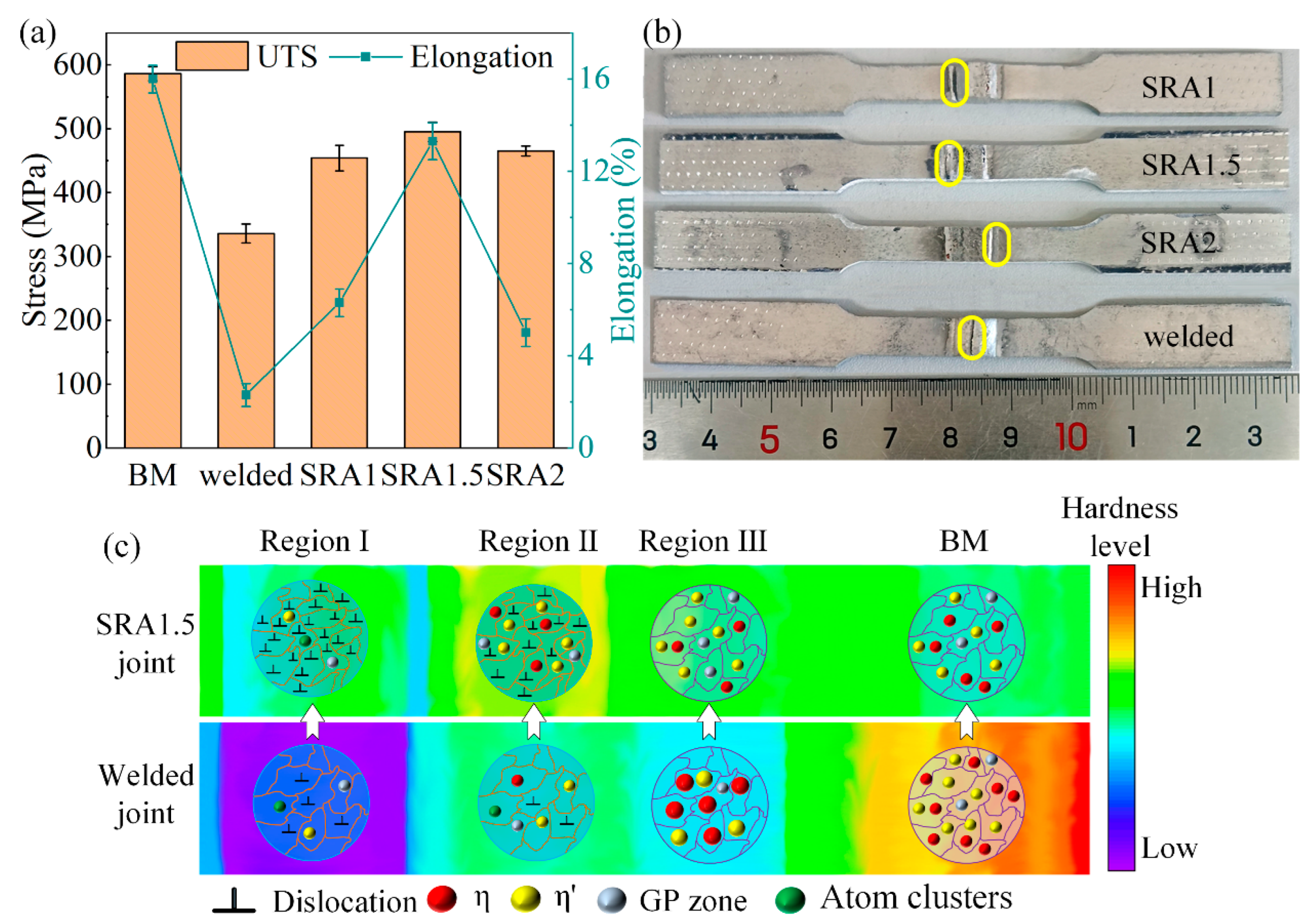
| Hot rolling then heat treatment | Weld beam | AA7075 | TIG | 336 | 479 | 2.3% | 3.9% | [157] |
| Cold rolling and heat treatment | Weld beam | AA7075 | TIG | 336 | 495 | 2.3% | 13.3% | [163] |
| Cold rolling then heat treatment | Weld beam | AA6061 | TIG | 214 | 305 | 6.4% | 9.8% | [164] |
| Fatigue life of welded joints (cycles) | Fatigue life of treated joints (cycles) | |||||||
| Rotation rolling | Weld beam | AA7050 | FSW | 3.6 × 10⁵ | 2.2 × 10⁶ | [159] | ||
| Heat treatment then deep rolling | The whole joint | AA7075 | FSW | 23,846 | 56,968 | [166] | ||
| High frequency impacting and rolling | The whole joint | AA2A12 | Plasma arc | 15,799 | 58,436 | [167] | ||
| Materials | Tensile Direction | UTS of Deposited (MPa) | YS of Deposited (MPa) | El of Deposited (%) | UTS of HDMR (MPa) | YS of HDMR (MPa) | El of HDMR (%) | Ref. |
|---|---|---|---|---|---|---|---|---|
| AA2319 | V | 314 | 244 | 6.2 | 262 | 130 | 15.5 | [171] |
| H | 325 | 250 | 8.5 | 263 | 135 | 18.6 | ||
| Al-4.7 Si | V | 134 | 52 | 12.3 | 159 | 72 | 16.2 | [172] |
| AA2319 | V | 267.8 | 109.4 | 14.5 | 293 | 119.9 | / | [173] |
| H | 296 | 111.3 | 23.0 | 324 | 122 | / | ||
| Al-Cu6.3 | V | 260 | / | / | 313.6 | / | / | [174] |
| Al-Mg4.5 | V | 290 | / | / | 342.8 | / | / | |
| AA2024 | H | 324 | 204 | 7.7 | 394 | 308 | 7.3 | [175] |
| V | 267 | 186 | 2.4 | 280 | 273 | 0.5 | ||
| AA5087 | H | 291 | 142 | 22.4 | 344 | 240 | 20.1 | [176] |
Disclaimer/Publisher’s Note: The statements, opinions and data contained in all publications are solely those of the individual author(s) and contributor(s) and not of MDPI and/or the editor(s). MDPI and/or the editor(s) disclaim responsibility for any injury to people or property resulting from any ideas, methods, instructions or products referred to in the content. |
© 2023 by the authors. Licensee MDPI, Basel, Switzerland. This article is an open access article distributed under the terms and conditions of the Creative Commons Attribution (CC BY) license (https://creativecommons.org/licenses/by/4.0/).
Share and Cite
Song, G.; Wang, Z.; Fan, X.; Liu, L. Research Progress of Aluminum Alloy Welding/Plastic Deformation Composite Forming Technology in Achieving High-Strength Joints. Materials 2023, 16, 7672. https://doi.org/10.3390/ma16247672
Song G, Wang Z, Fan X, Liu L. Research Progress of Aluminum Alloy Welding/Plastic Deformation Composite Forming Technology in Achieving High-Strength Joints. Materials. 2023; 16(24):7672. https://doi.org/10.3390/ma16247672
Chicago/Turabian StyleSong, Gang, Zejie Wang, Xiaoyu Fan, and Liming Liu. 2023. "Research Progress of Aluminum Alloy Welding/Plastic Deformation Composite Forming Technology in Achieving High-Strength Joints" Materials 16, no. 24: 7672. https://doi.org/10.3390/ma16247672