

The Historic Materials and Structures Due to the Aspect of Their Actual Challenges

Abstract
:1. Introduction
2. Materials and Methods
2.1. Loads
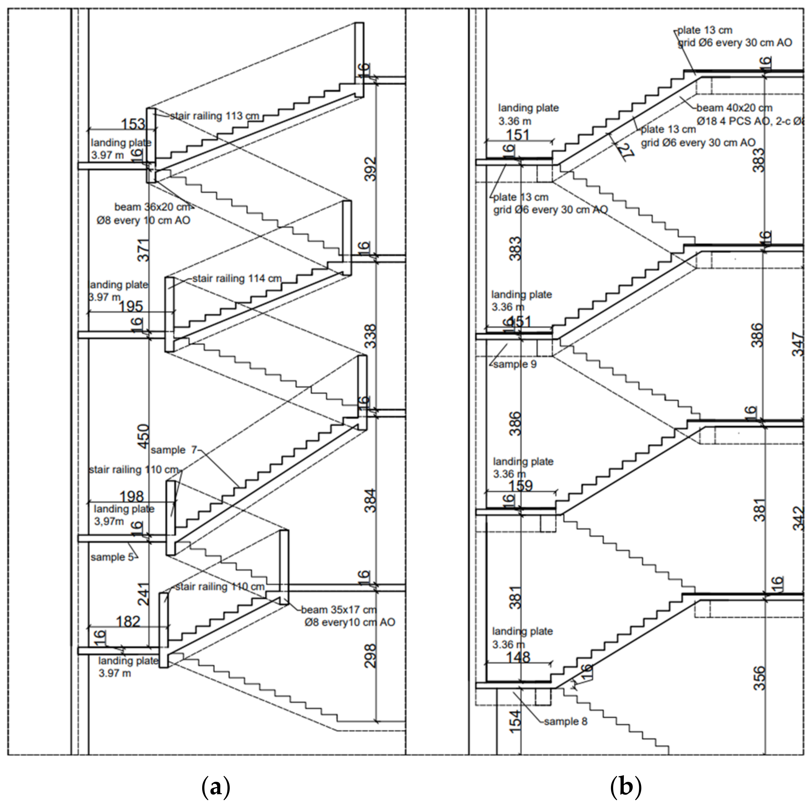
2.2. The Perfomance Technologies of Staircases
2.2.1. Concrete and Iron (Steel) for Reinforcement Bars—K1 and K2 Reinforced Concrete Staircase
“A derivation of formulas and calculation methods with small examplesA. Pure bending I. without considering concrete tensile stresses.(a) Simple reinforcement. The ratio of the modulus of elasticity of iron εe = 2,100,000 kg/cm2 to the modulus of elasticity of concrete εb = 140,000 kg/cm2εe/εb = n = 2,100,000/140,000 = 15”
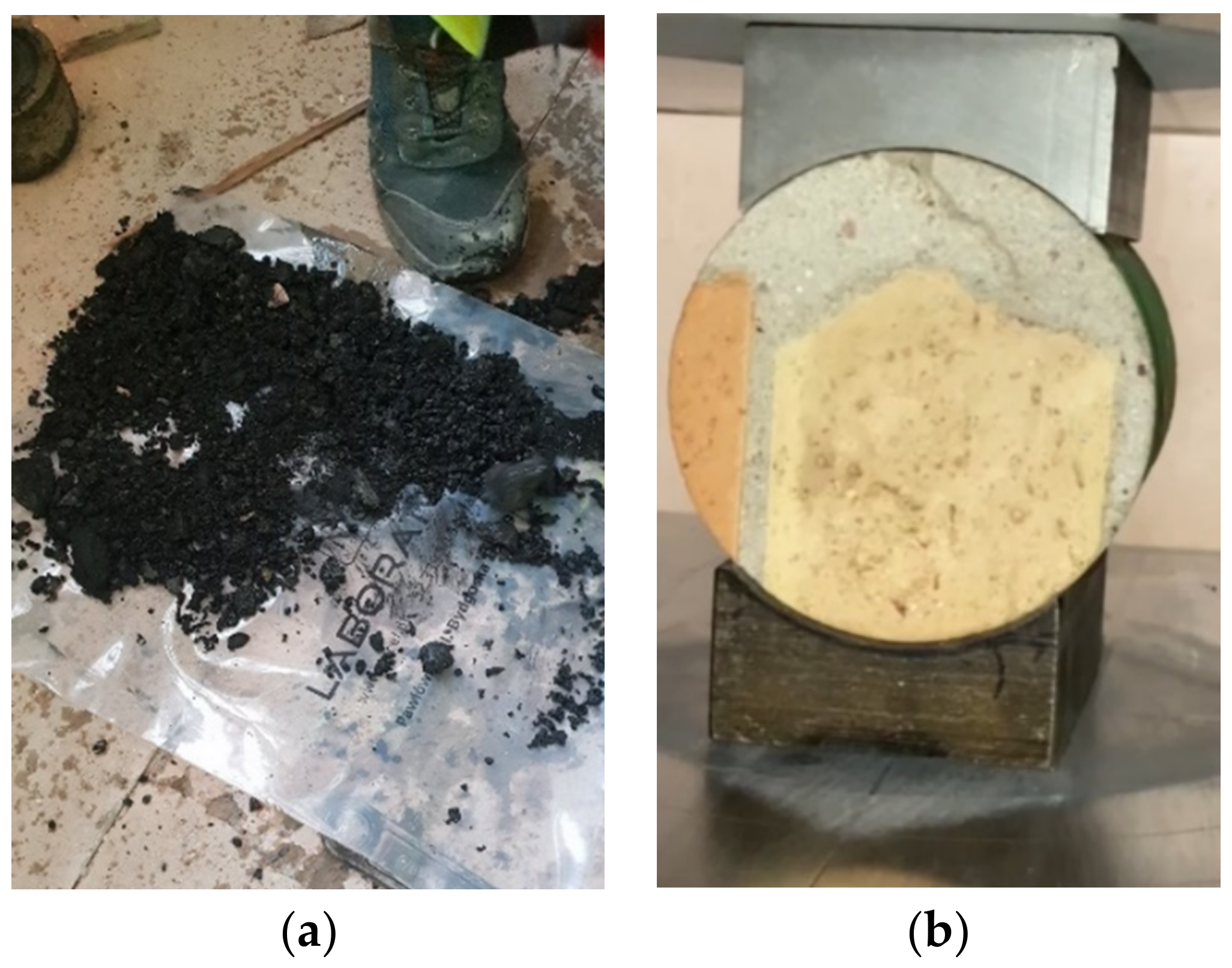
2.2.2. Ceramic K5 Staircase

| Sample No. | Sample Weight [kg] | Average Height of the Prepared Sample [mm] | Average Length of the Prepared Sample [mm] | Compression Strength f [N/mm2] |
|---|---|---|---|---|
| 1 (average-horizontal test) | 1.387 | 98 | 98 | 28.05 |
| 1a | 1.385 | 97 | 98 | 27.09 |
| 2a | 1.385 | 98 | 97 | 28.15 |
| 2b | 1.387 | 97 | 99 | 28.20 |
| 1d | 1.387 | 98 | 98 | 28.23 |
| 1e | 1.387 | 98 | 98 | 28.31 |
| 1f | 1.387 | 98 | 98 | 28.05 |
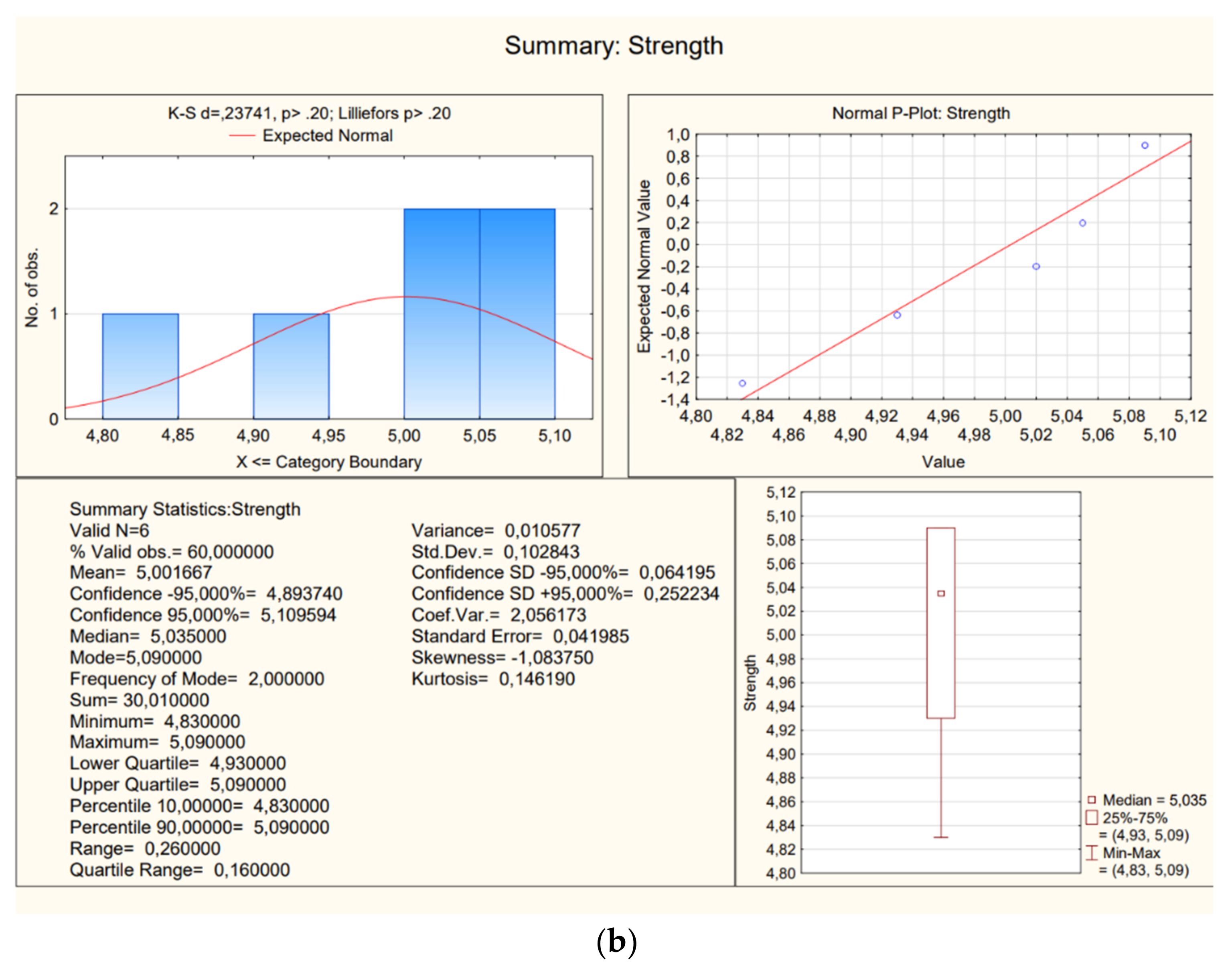
| 2 (average-vertical test) | 0.867 | 122 | 98 | 5.00 |
| 2a | 0.872 | 123 | 99 | 5.05 |
| 2b | 0.863 | 121 | 98 | 4.93 |
| 2c | 0.866 | 122 | 97 | 4.83 |
| 2d | 0.867 | 122 | 97 | 5.09 |
| 2e | 0.869 | 123 | 99 | 5.02 |
| 2f | 0.863 | 121 | 97 | 5.09 |
3. Results
3.1. K5 Ceramic Staircase
3.2. K1 Reinforced Concrete Staircase
| Sample No. | Sample Weight [kg] | Average Height of the Prepared Sample [mm] | Average Length of the Prepared Sample [mm] | Strength on Compression f [N/mm2] |
|---|---|---|---|---|
| 5 (average) | 1.480 | 98 | 85 | 36.4 |
| 5a | 1.45 | 99 | 83 | 36.3 |
| 5b | 1.5 | 96 | 86 | 35.9 |
| 5c | 1.49 | 97 | 86 | 37 |
| 5d | 1.48 | 98 | 84 | 36.5 |
| 5e | 1.48 | 98 | 86 | 36.4 |
| 5f | 1.46 | 99 | 84 | 36.2 |
| 7 (average) | 0.867 | 98 | 98 | 22.3 |
| 7a | 0.859 | 95 | 96 | 22.3 |
| 7b | 0.873 | 100 | 94 | 22 |
| 7c | 0.862 | 99 | 97 | 22.3 |
| 7d | 0.865 | 97 | 99 | 23 |
| 7e | 0.866 | 98 | 99 | 21.9 |
| 7f | 0.875 | 98 | 100 | 22.5 |
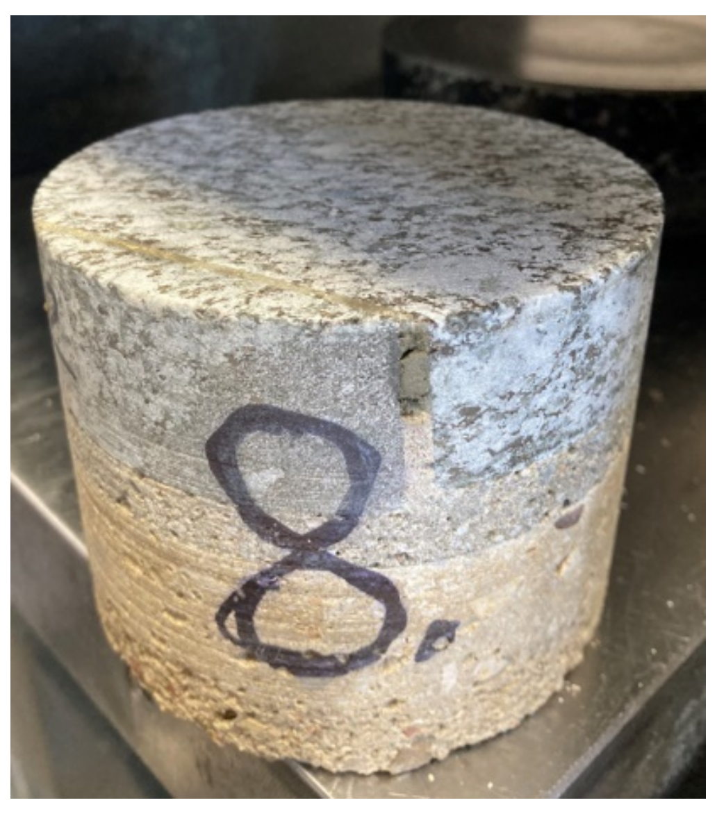
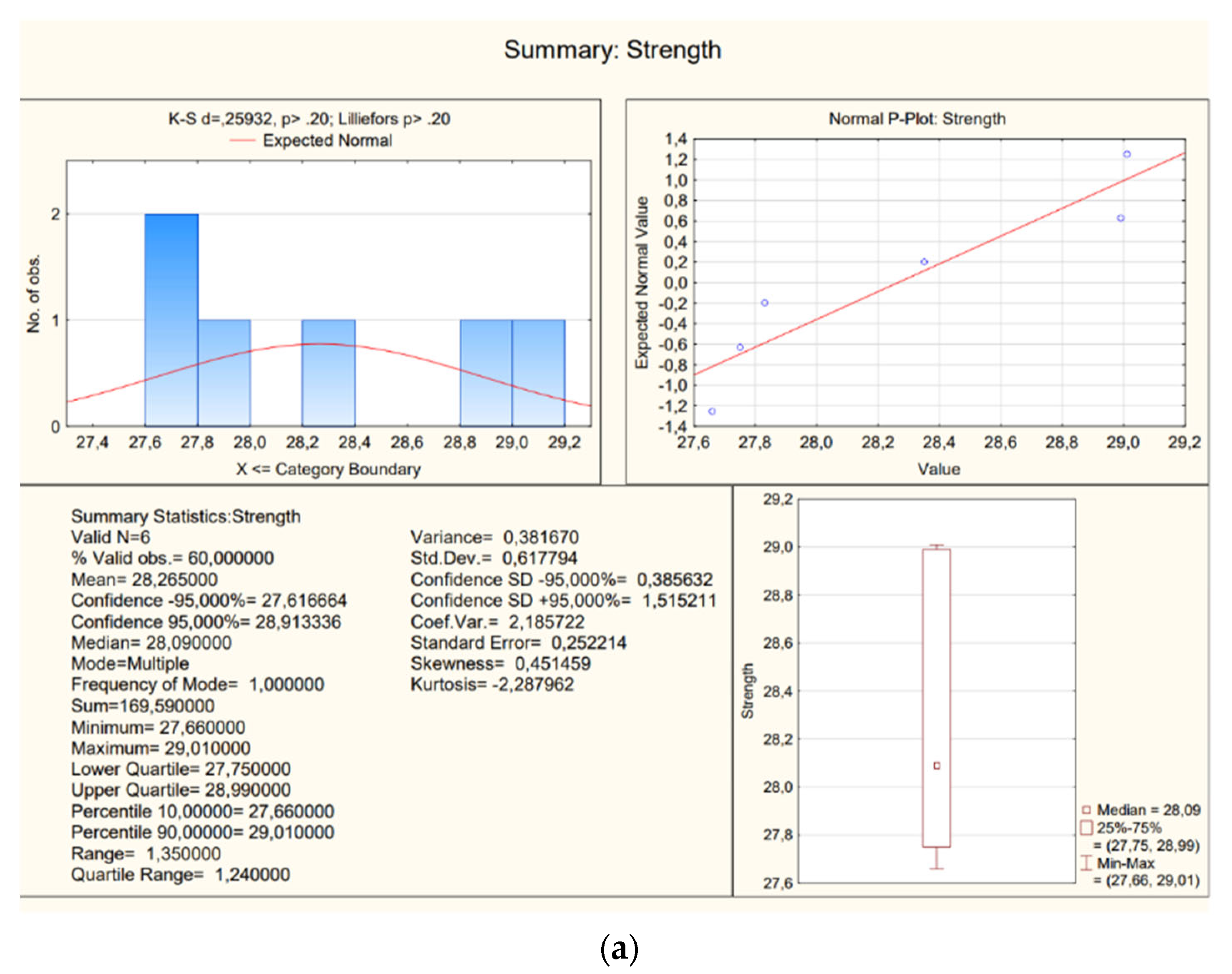
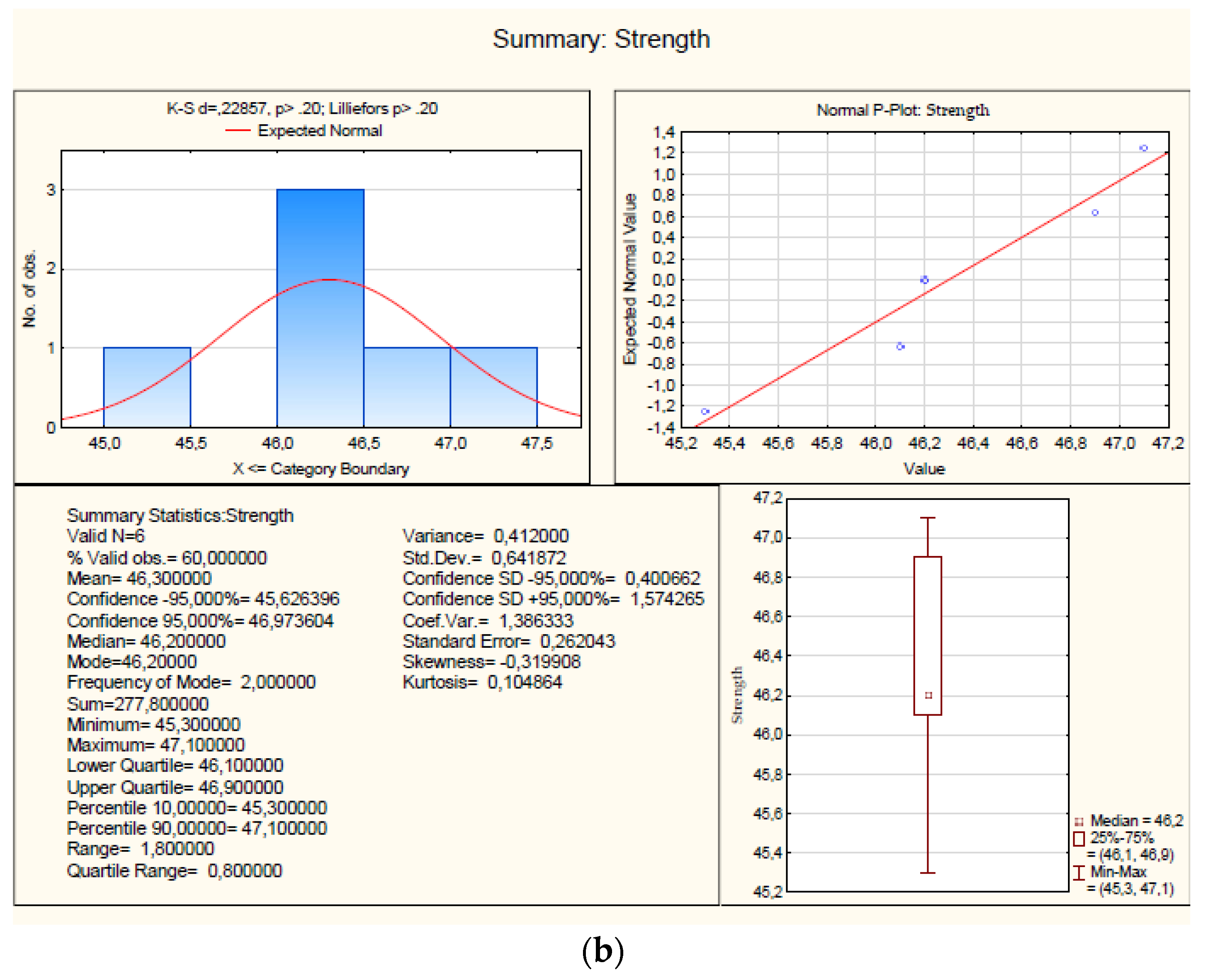
3.3. K2 Reinforced Concrete Staircase
| Sample No. | Sample Weight [kg] | Average Height of the Prepared Sample [mm] | Average Length of the Prepared Sample [mm] | Strength on Compression f [N/mm2] |
|---|---|---|---|---|
| 8- average | 1.45 | 98 | 80 | 28.27 |
| 8a | 1.46 | 99 | 78 | 28.35 |
| 8b | 1.44 | 96 | 79 | 29.01 |
| 8c | 1.47 | 95 | 82 | 27.66 |
| 8d | 1.42 | 97 | 80 | 28.99 |
| 8e | 1.46 | 99 | 87 | 27.83 |
| 8f | 1.45 | 98 | 76 | 27.75 |
| 9- average | 1.19 | 98 | 70 | 46.3 |
| 9a | 1.2 | 98 | 70 | 47.1 |
| 9b | 1.23 | 96 | 71 | 45.3 |
| 9c | 1.15 | 99 | 73 | 46.2 |
| 9d | 1.34 | 97 | 72 | 46.9 |
| 9e | 1.13 | 98 | 69 | 46.1 |
| 9f | 1.17 | 99 | 67 | 46.2 |
4. A Proposal to Strengthen the Existing Structures
5. Discussion and Conclusions
“If the calculations are to be carried out for a strip with a width of b = 1.00 m, then the width of the stairs can be freely changed without reducing the correctness of the calculations. The average thickness of the steps 18/2 = 9 cmoperational load—400 kg/m2steps—180 kg/m2landing plate—408 kg/m2 total load—p = 1000 kg/m2plaster—12 kg/m2Since the running plates of the stairs together with the landing plates are a load-bearing structure with many sub-pores, according to the guidelines of the Ministry, the bending moment in the middle of the board should be Mśr = pl2/10 × 100. Dimensioning should be carried out in accordance with table II in the formula book (page 14 no. 15), specifically for the compressive stress of concrete σb ≤ 40 kg/cm2 and for the tensile stress of iron σb ≤ 1000 kg/cm2.”
Author Contributions
Funding
Institutional Review Board Statement
Informed Consent Statement
Data Availability Statement
Conflicts of Interest
References
- ITB Safety Principles Assessment of Reinforced Concrete Structures 1999. Available online: https://www.itb.pl/instrukcje-wytyczne-poradniki (accessed on 6 January 2023).
- Giergiczny, Z.; Batog, M.; Synowiec, K. Cement and concrete. Mag. Highways 2018, 8, 62–67. [Google Scholar]
- Teomete, E.; Tayfur, G.; Aktaş, E. Estimation of mechanical properties of limestone using regression analyses and ANN. Cem. Wapno Bet. 2012, 17, 373–389. [Google Scholar]
- Maj, M.; Ubysz, A.; Hammadeh, H.; Askifi, F. Non-destructive testing of technical conditions of RC industrial tall chimneys subjected to high temperature. Materials 2019, 12, 2027. [Google Scholar] [CrossRef] [Green Version]
- Kaminski, M.; Maj, M.; Ubysz, A. Chimney cracked reinforced concrete walls as a problem of durability exploitation. In Proceedings of the Fifth International Conference on Structural Engineering (SEMC 2013), Cape Town, South Africa, 2–4 September 2013. [Google Scholar]
- Bajno, D.; Bednarz, Ł.; Grzybowska, A. The Role and Place of Traditional Chimney System Solutions in Environmental Progress and in Reducing Energy Consumption. Energies 2021, 14, 4720. [Google Scholar] [CrossRef]
- Malier, Y. High Performance Concrete; E&FN Spon: London, UK, 1992. [Google Scholar]
- Lai, S.; Serra, M. Concrete strength prediction by means of neural network. Constr. Build. Mater. 1997, 11, 93–98. [Google Scholar] [CrossRef]
- Schifman, J. The Rock Solid History of Concrete 2017. Available online: https://www.popularmechanics.com/technology/infrastructure/a28502/rock-solid-history-of-concrete/ (accessed on 6 January 2023).
- Dobiszewska, M.; Schindler, A.K.; Pichór, W. Mechanical properties and interfacial transition zone microstructure of concrete with waste basalt powder addition. Constr. Build. Mater. 2018, 177, 222–229. [Google Scholar] [CrossRef]
- Lorenzi, A.; Caetano, L.F.; Chies, J.A.; da Silva Filho, L.C.P. Investigation of the Potential for Evaluation of Concrete Flaws Using Nondestructive Testing Methods. ISRN Civ. Eng. 2014, 2014, 543090. [Google Scholar] [CrossRef] [Green Version]
- Panedpojaman, P.; Tonnayopas, D. Rebound hammer test to estimate compressive strength of heat exposed concrete. Constr. Build. Mater. 2018, 172, 387–395. [Google Scholar] [CrossRef]
- Hoła, J.; Schabowicz, K. State-of-the-art non-destructive methods for diagnostic testing of building structures—Anticipated development trends. Arch. Civ. Mech. Eng. 2010, 10, 5–18. [Google Scholar] [CrossRef]
- Ahmed, A.; Mateo-Garcia, M.; Arewa, A.; Caratella, K. Integrated Performance Optimization of Higher Education Buildings Using Low-Energy Renovation Process and User Engagement. Energies 2021, 14, 1475. [Google Scholar] [CrossRef]
- Ujma, A.; Kysiak, A. Diagnostics of building structure elements with use of thermal imaging camera. Constr. Optim. Energy Potential 2015, 182–190. [Google Scholar]
- Wałach, D.; Dybeł, P.; Jaskowska-Lemańska, J. Diagnostics of transport construction structures made of high-performance concrete. Logistics 2014, 6, 10802–10810. [Google Scholar]
- Ahn, E.; Kim, H.; Sim, S.-H.; Shin, S.; Shin, M. Principles and Applications of Ultrasonic-Based Nondestructive Methods for Self-Healing in Cementitious Materials. Materials 2017, 10, 278. [Google Scholar] [CrossRef] [PubMed] [Green Version]
- Hoła, J.; Bień, J.; Sadowski, Ł.; Schabowicz, K. Non-destructive and semi-destructive diagnostics of concrete structures in assessment of their durability. Bull. Polish Acad. Sci. Tech. Sci. 2015, 63, 87–96. [Google Scholar] [CrossRef]
- Hong, S.; Yoon, S.; Kim, J.; Lee, C.; Kim, S.; Lee, Y. Evaluation of Condition of Concrete Structures Using Ultrasonic Pulse Velocity Method. Appl. Sci. 2020, 10, 706. [Google Scholar] [CrossRef] [Green Version]
- PN-82/B-02001; Structure Loads. Permanent Loads. PKN: Płock, Poland, 1982.
- PN-82/B-2003; Technological Variable Loads. Basic Technological and Assembly Loads. PKN: Płock, Poland, 1982.
- PN-76/B-03264; Concrete, Reinforced Concrete and Prestressed Structures. Static Calculations and Design. PKN: Płock, Poland, 1976.
- PN-B-03264:2002; Concrete, Reinforced concrete And Prestressed Structures. Static Calculations and Design. PKN: Płock, Poland, 2002.
- PN-87/B-03002; Masonry Structures. Static Calculations and Design. PKN: Płock, Poland, 1987.
- Engineering Handbook in Civil Engineering Range; Part I–III; Professor Stefan Bryła, I.S. (Ed.) Redaction: Warsaw, Poland, 1932. [Google Scholar]
- Bajno, D.; Grzybowska, A.; Trzyński, I. Technical Opinion of the Proposed Replacement Historic Staircase Structures in Education and Training Buildings. Gorzów Wielkopolski, Opole, Poland, 2022. [Google Scholar]
- Bajno, D. Technical Opinion. Opole, Poland, 2021. [Google Scholar]
- Laboratorium, A.-C. Testing of Concrete and Ceramic Elements of Staircases K1, K2 and K5. Chojnice, Poland, 2022. [Google Scholar]
- Bajno, D.; Grzybowska, A.; Trzyński, I. Inventory of Staircase Structures Prepared for the Opinion. Chojnice, Poland, 2022. [Google Scholar]
- Laboratory Barg. Test Report—Selected Material Tests in the Revitalized Post-Hospital Building at ul. Warszawska in Gorzów (Compression Test of Core Boreholes, Determination of Cover Thickness, Reinforcement Spacing and Diameters). Poznań, Poland, 2021. [Google Scholar]
- Laboratory Barg. Research Report—Selected Material Tests in a Revitalized Post-Hospital Building at ul. Warszawska in Gorzów (Staircases: Transitional, K1 and K2). Gorzów Wielkopolski, Poland, 2021. [Google Scholar]
- Laboratory Barg. Research Report—Selected Material Tests in a Revitalized Post-Hospital Building at ul. Warszawska in Gorzów (Brick Compression Test, Determination of Cover Thickness, Reinforcement Spacing and Diameters). Gorzów Wielkopolski, Poland, 2021. [Google Scholar]
- Toensmann, A. Der Eisenbetonbau von A. Toensmann Zivil-Ingenieur; Eisenbeton; Akademie Wismar a. Ostsee: Berlin, Germany, 1910. [Google Scholar]
- Czapliński, K. Old Iron Alloy Products; DWE: Opole, Poland, 2009. [Google Scholar]
- Alsaleem, F.M.; Abiprojo, R.; Arensmeier, J.; Hemmelgarn, G. HVAC system cloud based diagnostics model. In Proceedings of the International Refrigerant and Air Conditioning Conference, No 1508, West Lafayette, IN, USA, 14–17 July 2014. [Google Scholar]
- Bashi, A.; Jilkov, V.; Li, X. Fault detection for systems with multiple unknown modes and similar units and its application to HVAC. IEEE Trans. Control. Syst. Technol. 2011, 19, 957–968. [Google Scholar] [CrossRef]
- Bonvini, M.; Wetter, M.; Sohn, M. An FMI-based toolchain for the adoption of model-base FDD. In Proceedings of the ASHRAE/IBPSA-USA Building Simulation Conference 2014, Atlanta, GA, USA, 10–12 September 2014. [Google Scholar]
- Brambley, M.R.; Fernandez, N.; Wang, W.; Cort, K.; Cho, H.; Ngo, H.; Goddard, J. Self-Correcting Controls for VAV System Faults, Filter/Fan/Coil and VAV Box. PNNL- 20452; U.S Department of Energy: Washington, DC, USA, 2011.
- Costa, A.; Keane, M.; Torrens, J.; Corry, E. Building operation and energy performance: Monitoring, analysis and optimisation toolkit. Appl. Energy 2013, 101, 310–316. [Google Scholar] [CrossRef]
- Fan, B.; Du, Z.; Jin, X.; Yang, X.; Guo, Y. A hybrid FDD strategy for local system of AHU based on artificial neural network and wavelet analysis. Build. Environ. 2010, 45, 2698–2708. [Google Scholar] [CrossRef]
- Han, H.; Gu, B.; Hong, Y.; Kang, J. Automated FDD of multiple-simultaneous faults (MSF) and the application to building chillers. Energy Build. 2011, 43, 2524–2532. [Google Scholar] [CrossRef]
- Han, H.; Gu, B.; Wang, T.; Li, Z. Important sensors for chiller fault detection and diagnosis (FDD) from the perspective of feature selection and machine learning. Int. J. Refrig. 2012, 34, 586–599. [Google Scholar] [CrossRef]
- Hao, X.; Zhang, G.; Chen, Y. Fault-tolerant control and data recovery in HVAC monitoring system. Energy Build. 2005, 37, 175–180. [Google Scholar] [CrossRef]
- Katipamula, S.; Brambley, M.A. Review article: Methods for fault detection, diagnostics, and prognostics for building systems—A review, Part I. HVAC&R Res. 2005, 11, 3–25. [Google Scholar]
- Katipamula, S.; Brambley, M.A. Review article: Methods for fault detection, diagnostics, and prognostics for building systems—A review, part II. HVAC&R Res. 2005, 11, 169–187. [Google Scholar]
- Lauro, F.; Moretti, F.; Capozzoli, A.; Khan, I.; Pizzuti, S.; Macas, M.; Panzieri, S. Building fan coil electric consumption analysis with fuzzy approaches for fault detection and diagnosis. Energy Procedia 2014, 62, 411–420. [Google Scholar] [CrossRef]
- Narayanaswamy, B.; Balaji, B.; Gupta, R.; Agarwal, Y. Data driven investigation of faults in HVAC systems with model, cluster and compare (MCC). In Proceedings of the 1st ACM Conference on Embedded Systems for Energy-Efficient Buildings, New York, NY, USA, 3–6 November 2014; pp. 50–59. [Google Scholar]
- Nassif, N.; Moujaes, S.; Zaheeruddin, M. Self-tuning dynamic models of HVAC system components. Energy Build. 2008, 40, 1709–1720. [Google Scholar] [CrossRef]
- O’Neill, Z.; Pang, X.; Shashanka, M.; Haves, P.; Bailey, T. Model-based real-time whole building energy performance monitoring and diagnostics. J. Build. Perform. Simul. 2014, 7, 83–99. [Google Scholar] [CrossRef]
- Song, Y.H.; Akashi, Y.; Yee, J. A development of easy-to-use tool for fault detection and diagnosis in building air-conditioning systems. Energy Build. 2008, 40, 71–82. [Google Scholar] [CrossRef]
- Srivastav, A.; Tewari, A.; Dong, B. Baseline building energy modeling and localized uncertainty quantification using Gaussian mixture models. Energy Build. 2013, 65, 438–447. [Google Scholar] [CrossRef]
- Wang, S.; Zhou, Q.; Xiao, F. A system-level fault detection and diagnosis strategy for HVAC systems involving sensor faults. Energy Build. 2010, 42, 477–490. [Google Scholar] [CrossRef]
- Zhu, Y.; Jin, X.; Du, Z. Fault diagnosis for sensors in air handling unit based on neural network pre-processed by wavelet and fractal. Energy Build. 2012, 44, 7–16. [Google Scholar] [CrossRef]
- Zogg, D.; Shafai, E.; Geering, H. Fault diagnosis for heat pumps with parameter identification and clustering. Control. Eng. Practice 2006, 14, 1435–1444. [Google Scholar] [CrossRef]


Disclaimer/Publisher’s Note: The statements, opinions and data contained in all publications are solely those of the individual author(s) and contributor(s) and not of MDPI and/or the editor(s). MDPI and/or the editor(s) disclaim responsibility for any injury to people or property resulting from any ideas, methods, instructions or products referred to in the content. |
© 2023 by the authors. Licensee MDPI, Basel, Switzerland. This article is an open access article distributed under the terms and conditions of the Creative Commons Attribution (CC BY) license (https://creativecommons.org/licenses/by/4.0/).
Share and Cite
Bajno, D.; Grzybowska, A.; Trzyński, I. The Historic Materials and Structures Due to the Aspect of Their Actual Challenges. Materials 2023, 16, 2302. https://doi.org/10.3390/ma16062302
Bajno D, Grzybowska A, Trzyński I. The Historic Materials and Structures Due to the Aspect of Their Actual Challenges. Materials. 2023; 16(6):2302. https://doi.org/10.3390/ma16062302
Chicago/Turabian StyleBajno, Dariusz, Agnieszka Grzybowska, and Ireneusz Trzyński. 2023. "The Historic Materials and Structures Due to the Aspect of Their Actual Challenges" Materials 16, no. 6: 2302. https://doi.org/10.3390/ma16062302