

Influence of Insertion Torques on the Surface Integrity in Different Dental Implants: An Ex Vivo Descriptive Study
 , , and
Abstract
:1. Introduction
2. Materials and Methods
2.1. Study Design
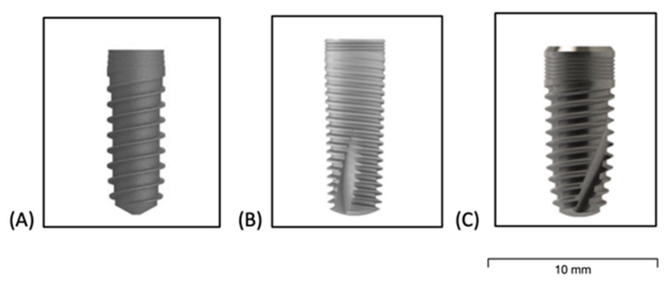
- Group A;
- Group B;
- Group C.
2.2. Sample Size Calculation
2.3. Pre-Surgical Protocol
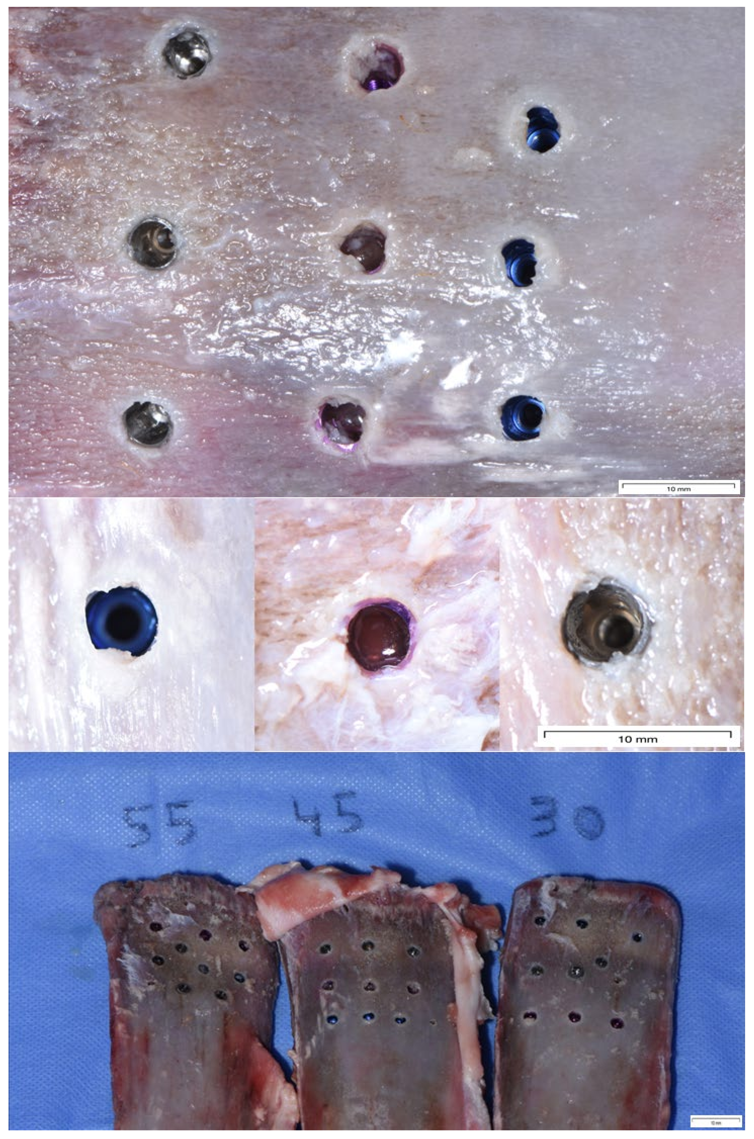
2.4. Surgical Protocol
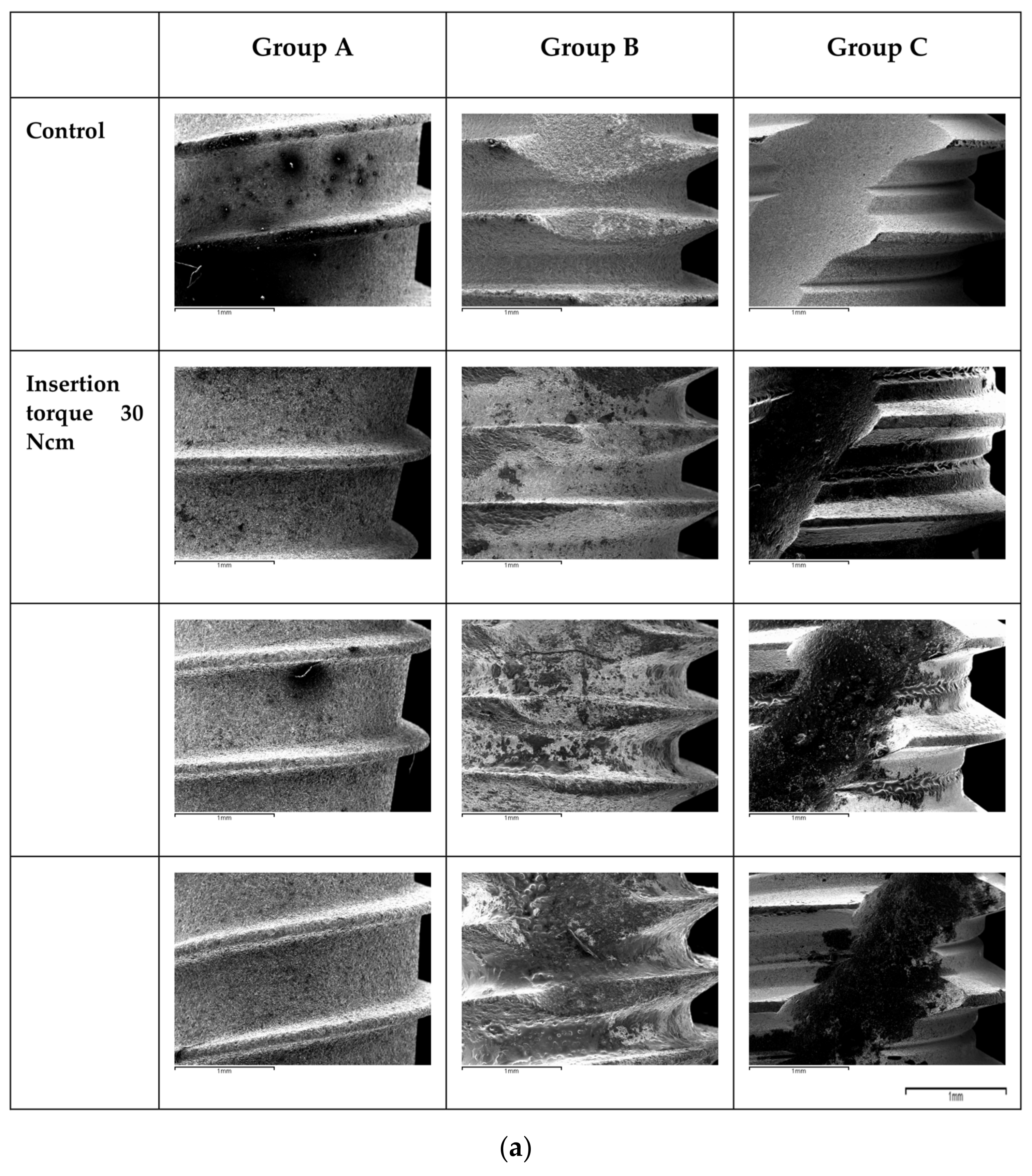
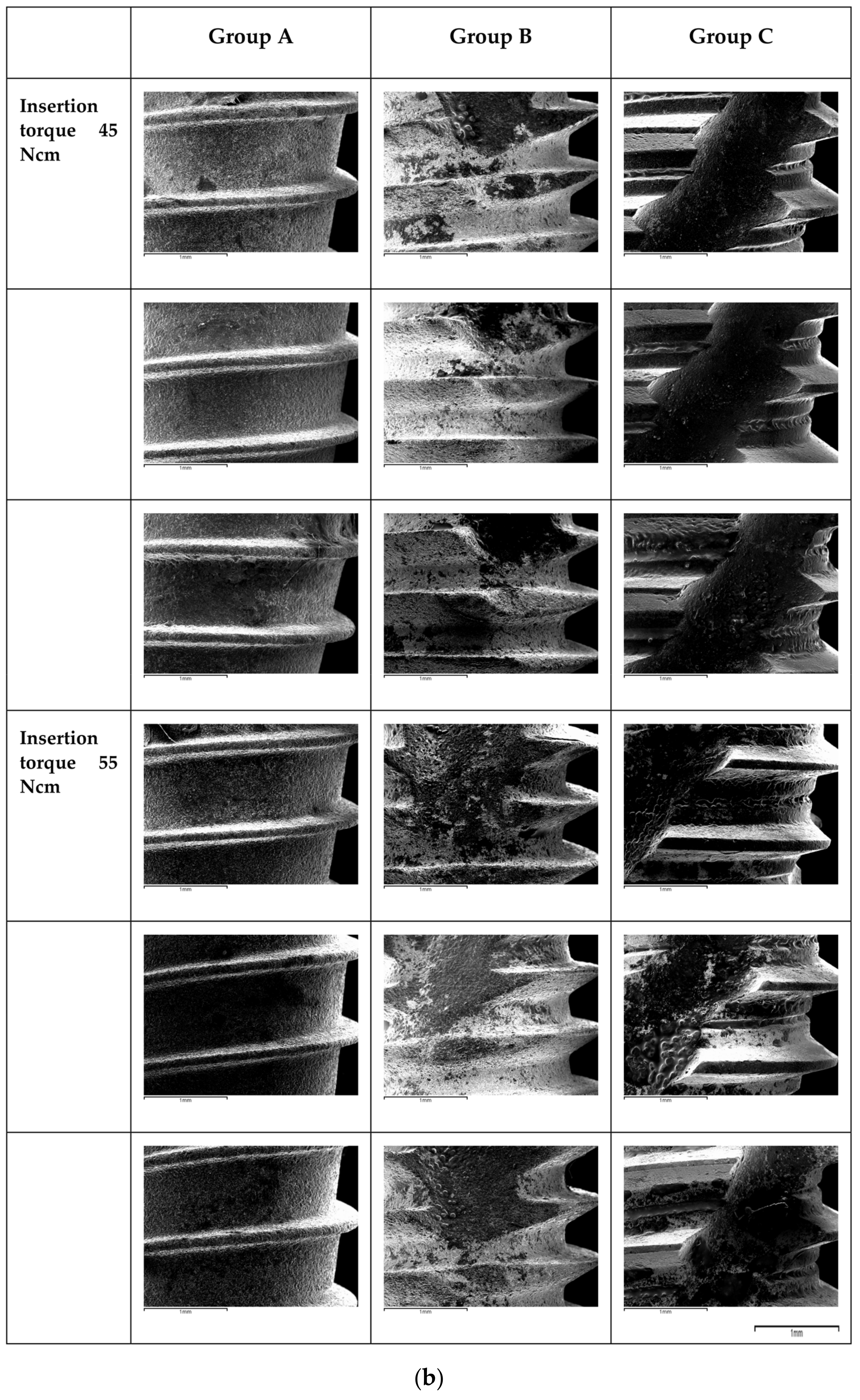
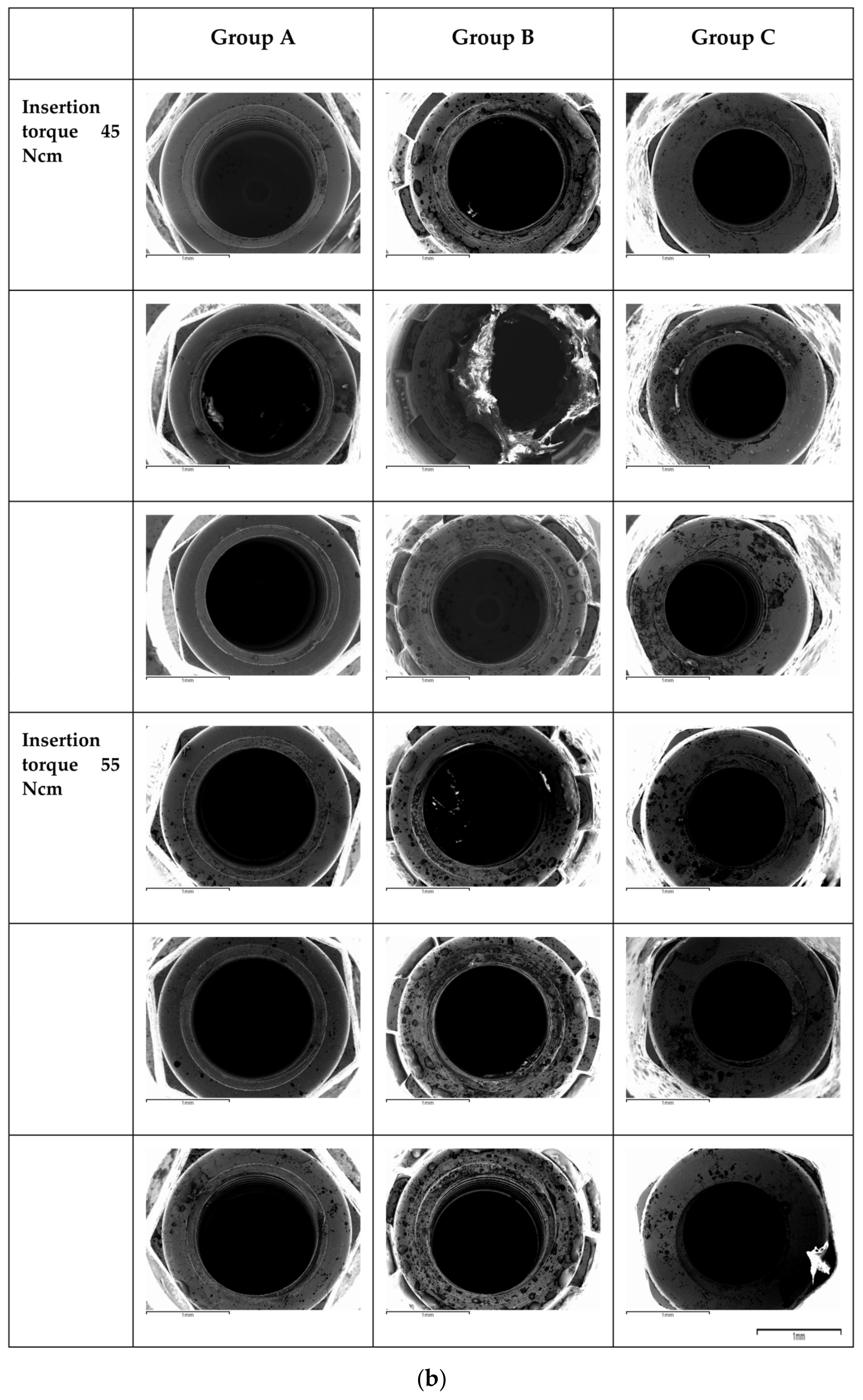
2.5. Microscopic Analysis
3. Results
4. Discussion
4.1. Surface Damage at the Level of the Apical Third
4.2. Surface Damage at the Level of the Connection
4.3. Impact of the Surface Damage: Titanium Release
4.4. Impact of the Material Properties
4.5. Limitations of the Study
5. Conclusions
Author Contributions
Funding
Institutional Review Board Statement
Informed Consent Statement
Data Availability Statement
Acknowledgments
Conflicts of Interest
References
- Eliasa, C.N.; Rocha, F.A.; Nascimento, A.L.; Coelho, P.G. Influence of implant shape, surface morphology, surgical technique and bone quality on the primary stability of dental implants. J. Mech. Behav. Biomed. Mater. 2012, 16, 169–180. [Google Scholar] [CrossRef]
- Friberg, B.; Sennerby, L.; Gröndahl, K.; Bergström, C.; Bäck, T.; Lekholm, U. On cutting torque measurements during implant placement: A 3-year clinical prospective study. Clin. Implant. Dent. Relat. Res. 1999, 1, 75–83. [Google Scholar] [CrossRef] [PubMed]
- O’Sullivan, D.; Sennerby, L.; Meredith, N. Measurements comparing the initial stability of five designs of dental implants: A human cadaver study. Clin. Implant. Dent. Relat. Res. 2000, 2, 85–92. [Google Scholar] [CrossRef] [PubMed]
- Ottoni, J.; Oliveira, Z.F.L.; Mansini, R.; Cabral, A.D.M. Correlation between placement torque and survival of single-tooth implants. Int. J. Oral Maxillofac. Implant. 2005, 20, 769–776. [Google Scholar]
- Trisi, P.; Perfetti, G.; Baldoni, E.; Berardi, D.; Colagiovanni, M.; Scogna, G. Implant micromotion is related to peak insertion torque and bone density. Clin. Oral Implant. Res. 2009, 20, 467–471. [Google Scholar] [CrossRef] [PubMed]
- Freitas, A.C.; Bonfante, E.A.; Giro, G.; Janal, M.N.; Coelho, P.G. The effect of implant design on insertion torque and immediate micromotion. Clin. Oral Implant. Res. 2012, 23, 113–118. [Google Scholar] [CrossRef] [PubMed]
- Perren, S.M. Evolution of the internal fixation of long bone fractures. The scientific basis of biological internal fixation: Choosing a new balance between stability and biology. J. Bone Jt. Surg. Br. 2002, 84, 1093–1110. [Google Scholar] [CrossRef]
- Bashutski, J.D.; D’Silva, N.J.; Wang, H.L. Implant compression necrosis: Current understanding and case report. J. Periodontol. 2009, 80, 700–704. [Google Scholar] [CrossRef] [Green Version]
- Trisi, P.; Todisco, M.; Consolo, U.; Travaglini, D. High versus low implant insertion torque: A histologic, histomorphometric, and biomechanical study in the sheep mandible. Int. J. Oral Maxillofac. Implant. 2011, 26, 837–849. [Google Scholar]
- Teixeira, A.B.v.; Beja, G.B.S.P.; Shimano, A.C.; Macedo, A.P.; Oliscovicz, N.F.; dos Reis, A.C. Influence of the ultimate torsion on the geometry of dental implants. Braz. Dent. J. 2013, 24, 213–217. [Google Scholar] [CrossRef] [Green Version]
- Wennerberg, A. On Surface Roughness and Implant Incorporation; University of Göteborg: Gothenburg, Sweden, 1996. [Google Scholar]
- Baggi, L.; Cappelloni, I.; di Girolamo, M.; Maceri, F.; Vairo, G. The influence of implant diameter and length on stress distribution of osseointegrated implants related to crestal bone geometry: A three-dimensional finite element analysis. J. Prosthet. Dent. 2008, 100, 422–431. [Google Scholar] [CrossRef] [PubMed] [Green Version]
- Aldahlawi, S.; Demeter, A.; Irinakis, T. The effect of implant placement torque on crestal bone remodeling after 1 year of loading. Clin. Cosmet. Investig. Dent. 2018, 10, 203–209. [Google Scholar] [CrossRef] [PubMed] [Green Version]
- Duyck, J.; Corpas, L.; Vermeiren, S.; Ogawa, T.; Quirynen, M.; Vandamme, K.; Jacobs, R.; Naert, I. Histological, histomorphometrical, and radiological evaluation of an experimental implant design with a high insertion torque. Clin. Oral Implant. Res. 2010, 21, 877–884. [Google Scholar] [CrossRef] [PubMed]
- Irinakis, T.; Wiebe, C. Initial torque stability of a new bone condensing dental implant. A cohort study of 140 consecutively placed implants. J. Oral Implantol. 2009, 35, 277–282. [Google Scholar] [CrossRef]
- Turkyilmaz, I.; Sennerby, L.; McGlumphy, E.A.; Tözüm, T.F. Biomechanical aspects of primary implant stability: A human cadaver study. Clin. Implant. Dent. Relat. Res. 2009, 11, 113–119. [Google Scholar] [CrossRef]
- Tabassum, A.; Meijer, G.J.; Wolke, J.G.C.; Jansen, J.A. Influence of surgical technique and surface roughness on the primary stability of an implant in artificial bone with different cortical thickness: A laboratory study. Clin. Oral Implant. Res. 2010, 21, 213–220. [Google Scholar] [CrossRef]
- Sotto-Maior, B.S.; Rocha, E.P.; de Almeida, E.O.; Freitas-Júnior, A.C.; Anchieta, R.B.; del Bel Cury, A.A. Influence of high insertion torque on implant placement: An anisotropic bone stress analysis. Braz. Dent. J. 2010, 21, 508–514. [Google Scholar] [CrossRef] [Green Version]
- Rupp, F.; Gittens, R.A.; Scheideler, L.; Marmur, A.; Boyan, B.D.; Schwartz, Z.; Geis-Gerstorfer, J. A review on the wettability of dental implant surfaces I: Theoretical and experimental aspects. Acta Biomater. 2014, 10, 2894–2906. [Google Scholar] [CrossRef] [Green Version]
- Søballe, K.; Brockstedt-Rasmussen, H.; Hansen, E.S.; Bünger, C. Hydroxyapatite coating modifies implant membrane formation. Controlled micromotion studied in dogs. Acta Orthop. Scand. 1992, 63, 128–140. [Google Scholar] [CrossRef] [Green Version]
- Soballe, K.; Hansen, E.S.; Brockstedt-Rasmussen, H.; Bunger, C. Hydroxyapatite coating converts fibrous tissue to bone around loaded implants. J. Bone Jt. Surg. Br. 1993, 75, 270–278. [Google Scholar] [CrossRef]
- Szmukler-Moncler, S.; Piattelli, A.; Favero, G.A.; Dubruille, J.H. Considerations preliminary to the application of early and immediate loading protocols in dental implantology. Clin. Oral Implant. Res. 2000, 11, 12–25. [Google Scholar] [CrossRef] [PubMed]
- Gehrke, S.A.; Pereira, G.M.A.; Gehrke, A.F.; de Bortoli Junior, N.; Dedavid, B.A. Effects of insertion torque on the structure of dental implants with different connections: Experimental pilot study in vitro. PLoS ONE 2021, 16, e0251904. [Google Scholar] [CrossRef] [PubMed]
- Mints, D.; Elias, C.; Funkenbusch, P.; Meirelles, L. Integrity of Implant Surface Modifications After Insertion. Int. J. Oral Maxillofac. Implant. 2014, 29, 97–104. [Google Scholar] [CrossRef] [Green Version]
- Senna, P.; Antoninha Del Bel Cury, A.; Kates, S.; Meirelles, L. Surface Damage on Dental Implants with Release of Loose Particles after Insertion into Bone. Clin. Implant. Dent. Relat. Res. 2015, 17, 681–692. [Google Scholar] [CrossRef] [PubMed] [Green Version]
- Kourtis, S.; Damanaki, M.; Kaitatzidou, S.; Kaitatzidou, A.; Roussou, V. Loosening of the fixing screw in single implant crowns: Predisposing factors, prevention and treatment options. J. Esthet. Restor. Dent. 2017, 29, 233–246. [Google Scholar] [CrossRef]
- De Barros Carrilho, G.P.; Dias, R.P.; Elias, C.N. Comparison of external and internal hex implants’ rotational freedom: A pilot study. Int. J. Prosthodont. 2005, 18, 165–166. [Google Scholar]
- Teixeira, A.B.v.; Shimano, A.C.; Macedo, A.P.; Valente, M.L.C.; dos Reis, A.C. Influence of torsional strength on different types of dental implant platforms. Implant. Dent. 2015, 24, 281–286. [Google Scholar] [CrossRef]
- Shin, D.K.; Kim, M.H.; Lee, S.H.; Kim, T.H.; Kim, S.Y. Inhibitory effects of luteolin on titanium particle-induced osteolysis in a mouse model. Acta Biomater. 2012, 8, 3524–3531. [Google Scholar] [CrossRef]
- Kaar, S.G.; Ragab, A.A.; Kaye, S.J.; Kilic, B.A.; Jinno, T.; Goldberg, V.M.; Bi, Y.; Stewart, M.C.; Carter, J.R.; Greenfield, E.M. Rapid repair of titanium particle-induced osteolysis is dramatically reduced in aged mice. J. Orthop. Res. 2001, 19, 171–178. [Google Scholar] [CrossRef]


Disclaimer/Publisher’s Note: The statements, opinions and data contained in all publications are solely those of the individual author(s) and contributor(s) and not of MDPI and/or the editor(s). MDPI and/or the editor(s) disclaim responsibility for any injury to people or property resulting from any ideas, methods, instructions or products referred to in the content. |
© 2023 by the authors. Licensee MDPI, Basel, Switzerland. This article is an open access article distributed under the terms and conditions of the Creative Commons Attribution (CC BY) license (https://creativecommons.org/licenses/by/4.0/).
Share and Cite
Brancacci, E.; García González, S.; Galve-Huertas, A.; Bennani, A.; Hernández Alfaro, F.; Aboul-Hosn Centenero, S. Influence of Insertion Torques on the Surface Integrity in Different Dental Implants: An Ex Vivo Descriptive Study. Materials 2023, 16, 2330. https://doi.org/10.3390/ma16062330
Brancacci E, García González S, Galve-Huertas A, Bennani A, Hernández Alfaro F, Aboul-Hosn Centenero S. Influence of Insertion Torques on the Surface Integrity in Different Dental Implants: An Ex Vivo Descriptive Study. Materials. 2023; 16(6):2330. https://doi.org/10.3390/ma16062330
Chicago/Turabian StyleBrancacci, Erika, Susana García González, Andrea Galve-Huertas, Aida Bennani, Federico Hernández Alfaro, and Samir Aboul-Hosn Centenero. 2023. "Influence of Insertion Torques on the Surface Integrity in Different Dental Implants: An Ex Vivo Descriptive Study" Materials 16, no. 6: 2330. https://doi.org/10.3390/ma16062330