1. Introduction
NiAl is widely used to produce heat-resistant alloys for the components of gas-turbine engines. The drawbacks of these alloys include low mechanical strength and ductility at room temperature, resulting in insufficient manufacturability and risk of failure [
1,
2,
3,
4,
5,
6,
7,
8]. Various plasticizers are added to alloys for increasing fracture toughness [
3,
4,
5,
6,
7,
8,
9,
10]. An essential requirement on hot gas path materials is the oxidation resistance of the surface at high temperatures and under thermocyclic loading [
11,
12,
13,
14,
15,
16,
17,
18,
19].
One of the known methods for producing cast and powder intermetallic-based materials is the self-propagating high-temperature synthesis (SHS) and its technological types: elemental synthesis [
20,
21,
22,
23,
24,
25] and centrifugal SHS casting [
25,
26,
27,
28,
29]. For both of them, research aiming to optimize the composition and modes for synthesizing CompoNiAl series alloys based on NiAl-Cr-Co (
base) is currently underway [
27,
28,
29,
30].
Microdoping with molybdenum and niobium (the
base+MoNb alloy) obtained by elemental synthesis enhances resistance to viscoplastic deformation at temperatures above 800 °C due to the formation of the Cr
0.5Mo
0.5 and Cr
0.7Mo
0.3 phases [
31,
32]. High-level mechanical properties were attained at 900 °C for the studied samples after HIP: σ
ucs = 615 ± 9 MPa; σ
ys = 488 ± 7 MPa; and ε
pd = 62.2 ± 1.4 %.
It was found for the cast SHS alloys
base+X (where
X = La,
Mo,
Ta,
Re,
Zr) [
32,
33] Reference addedthat doping the alloy with Mo and Re resulted in the formation of a cellular eutectic structure [
32]. Doping with up to 15% Mo and 1.5% Re improved mechanical properties up to the following values σ
ucs = 1604 ± 80 MPa, σ
ys = 1520 ± 80 MPa, and ε
pd = 0.79%; additional annealing at T = 1250 °C for 180 min enhanced the properties to σ
ucs = 1800 ± 80 MPa, σ
ys = 1670 ± 80 MPa, and ε
pd = 1.58%. In turn, rhenium modified the structure of the
base+15Mo1.5Re alloy, thus enhancing mechanical properties up to the values σ
ucs = 1682 ± 60 MPa, σ
ys = 1538 ± 60 MPa, and ε
pd = 0.87%; additional annealing further improved them to the values σ
ucs = 2019 ± 60 MPa, σ
ys = 1622 ± 60 MPa, and ε
pd = 5.88%. The hierarchical three-level structure of the
base+15%Mo alloy was identified: the first level was formed by dendritic
β-NiAl grains with interlayers of molybdenum-containing (Ni,Co,Cr)
3Mo
3C and (Mo
0.8Cr
0.2)
xB
y phases having a cell size up to 50 µm; the second level consisted of strengthening submicron-sized Cr(Mo) particles distributed along grain boundaries; and the third level comprised coherent Cr(Mo) nanoprecipitates (sized 10–40 nm) within the bulk of
β-NiAl dendrites. Doping with interstitial elements enhanced the oxidation resistance of the β-alloy due to the formation of additional phases [
33]. Volatile oxides MoO
3, Mo
3O
4 and CoMoO
4 disrupting the integrity of the protective layer were formed upon oxidation of alloys doped with molybdenum. Oxygen and nitrogen penetration depth increased with molybdenum concentration. In the tantalum-containing alloy, the Ta
2O
5 phase was formed in the intergrain space; this phase reduced the rate and depth of oxygen diffusion. The alloy doped with zirconium was characterized by the best high-temperature oxidation resistance; the extent of oxidation after 30 h was 21 g/m
2. The zirconium-containing continuous upper layer Al
2O
3 + Zr
5Al
3O
0.5 blocked the external diffusion of oxygen and nitrogen, thus increasing high-temperature oxidation resistance [
33]. Aheiev et al. [
33] also studied the effect of nitrogen dissolved in the alloy on the mechanism of high-temperature oxidation. Nitrogen reacts with aluminum to form aluminum nitride AlN, thus altering the oxidation mechanism. The vacuum induction melting (VIM) technique was used for degassing the alloy. The extent of oxidation after 30 h was 50 g/m
2 for the
base alloy and 22 g/m
2 for the
base+VIM alloy. However, the technological process of VIM is extensive; therefore, microdoping of alloys with metals (Ti, Zr, Hf, Re, etc.) exhibiting high chemical affinity for oxygen and nitrogen is performed to reduce the content of gas impurities. Thus, doping with titanium allowed one to bind gas impurities and noticeably reduce their content in the nickel aluminide-based solid solution, which had a positive effect on properties of the alloy [
1,
2]. Density increased [
32] and the end products became heavier with the rising content of rhenium dopant in
β-NiAl. Ruthenium is an expensive interstitial element but has an advantage over rhenium in terms of its density: ρ
Re = 21.02 g/cm
3 and ρ
Ru = 12.41 g/cm
3. Re and Ru exhibit similar effects: they stabilize the phase composition and ensure comminution of structural components, showing tendency toward low liquation during crystallization [
1]. Furthermore, ruthenium is an active getter of dissolved gases. The effect of Ru on the base composition of the
base alloy [
27,
28] has not been studied earlier.
Therefore, research into the effect of chemical composition on oxidation resistance, mechanical properties, and searching for the optimal compositions of the β-NiAl-based alloy is rather relevant today. This study aimed to produce cast NiAl-Cr-Co (base) alloys doped with complex additives by centrifugal SHS metallurgy and investigate the features of their microstructure, mechanical properties, kinetics and the mechanism of oxidation.
2. Materials and Methods
The calculated compositions of the alloys in the
base+X system are listed in
Table 1.
Synthesis was carried out using a radial-type centrifugal setup under high gravity conditions (up to 150 g). The general scheme of the employed centrifugal setup was provided in refs. [
23,
24,
25,
26].
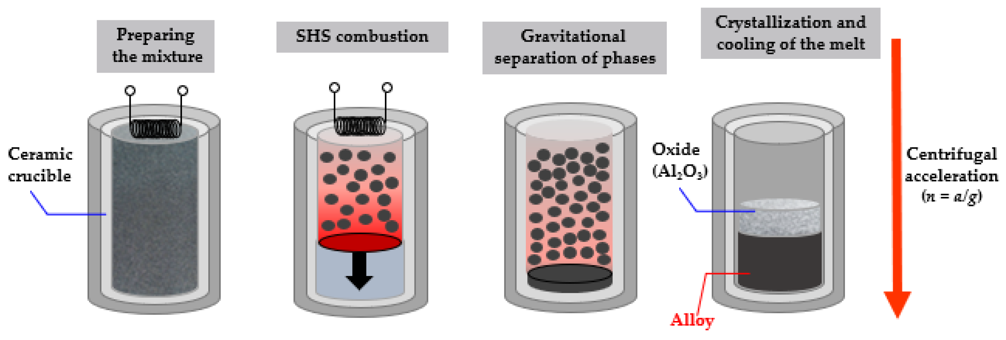
The design of the setup allows one to specify the number of revolutions of the centrifuge rotor in a controlled manner to ensure the desired acceleration level. A distinctive feature of this technology is that the relatively available oxide feedstock is used and high combustion temperature (2100–3500 °C) is attained, so the phase of the target product can be separated from the cinder phase. The chemical scheme of the process can be represented as:
where: FA (functional additive) is CaF
2, Na
3[AlF
6], etc; X is Me (Zr, Ta, Re, Ru, Ti, La).
Table 2 lists grades and properties of the initial powders. Dopants were added to the reaction mixture so as to obtain the desired composition of the alloy.
The scheme for preparing exothermic mixtures included drying the components in SNOL-type drying ovens at 90 °C during 1 h, dosing reagents, mixing and casting the mixture in graphite molds. Mixing was carried out in an MP4/0.5 planetary mill with a 1 L drum during 15–20 min at the ball-to-powder ratio of 1:5. The combustion temperature of the mixtures was higher than the melting point of the end products of synthesis, enabling complete phase segregation due to gravity separation of the metallic melt and cinder (
Figure 1). The Zr, Ta, Re, Ru and La components were added to the reaction mixture as pure elements, while Mo was added as MoO
3 oxide. Aluminum was used to reduce the oxide charge. Different grades of aluminum are used to control SHS processes [
25].
Thermodynamic calculations of the adiabatic combustion temperature (T
f) were preliminarily performed using the THERMO software ver.3 package. T
f was 2300–2400 °C for all the compositions under study, being noticeably higher than the melting points of the synthesis products. The optimal acceleration values for these systems were identified earlier and were equal to 140–150 g [
32]. The highest yield of the end product into a metal ingot was attained at this acceleration value. At least three ingots 80 mm in diameter and 25–30 mm high were synthesized for each composition (
Table 1), making it possible to study homogeneity and reproducibility of the results. According to the recommendations [
32], thermo-vacuum treatment (TVT) of the ingots was carried out at 1250 °C for 2 h to enhance ductility and residual strain. TVT led to strain relaxation, and the recrystallization of grains of the major
β-NiAl phase and excess phases. Furthermore, TVT contributed to the degassing of dissolved or adsorbed impurities (nitrogen and oxygen) [
33].
A Thermo Fisher Scientific Finnigan Element glow discharge mass spectrometer and a double-focusing spectrum analyzer (in the Nier–Johnson geometry) were employed for quantitative analysis of major components and impurities. This instrument was used to identify the chemical composition of both the base and impurity elements.
The phase composition was determined by X-ray phase analysis (XRD) on a D2 PHASER diffractometer (Bruker AXS GmbH, Mannheim, Germany) using Cu-Kα radiation in the 2θ range = 10–140°.
The microstructural studies were carried out on an S-3400N scanning electron microscope (Hitachi, Tokyo, Japan) coupled to a NORAN System 7 X-ray microanalysis system (Thermo Scientific, Waltham, MA, USA), as well as a JEM-2100 transmission electron microscope (TEM) (Jeol, Tokyo, Japan) using a Gatan 650 Single Tilt Rotation Analytical Specimen Holder (Gatan, Inc., Pleasanton, CA, USA). The samples (lamellae) were fabricated from the preliminarily prepared foil using the focused ion beam technique on a Quanta 200 3D FIB instrument (FEI Company, Hillsboro, OR, USA). TEM foils were prepared by ion etching on PIPS II system (Gatan, Inc., Pleasanton, CA, USA).
Compression tests were carried out on an LF-100KN universal testing machine (Walter+Bai AG, Löhningen, Switzerland) at room temperature in compliance with the State Standard GOST 25.503-97.
Oxidative annealing was carried out in air at 1150 °C during 30 h in an SShOL 1.1.6/12-M3 laboratory pit-type electric furnace; the samples were weighed periodically. Changes in sample weight normalized to the unit surface area over a certain time period were determined. The experimental data were used to plot the oxidation curves and fitting equations. Samples 8 mm in diameter and 4 mm high were cut on an EDM machine GX-320L (CHMER EDM, Taichung, Taiwan) and ground to a roughness of Rz = 5.
3. Results and Discussion
The low ductility of intermetallic alloys at room temperature impedes their practical application for fabricating geometrically complex items. The presence of detrimental impurities is an additional factor deteriorating properties of the alloys. Therefore, an important problem is controlling the chemical composition and impurity content in alloys. Chemical analysis of the synthesized ingots showed that they corresponded to the calculated compositions for the major components of the alloy.
Table 3 lists the impurity composition of
base-X alloys. The total contents of Mg, Na, Si, Ca, K, Fe Mn, Cu, W, S and C impurities are provided.
Impurity elements Mg, Na, Si, Ca, K, Mn and Cu are the accompanying ones and are transferred to the synthesis products from the starting reagents. The total impurity content is 0.15 ± 0.02 wt.%, which lies within the acceptance region for heat-resistant nickel alloys. Meanwhile, technical solutions that would reduce their concentration need to be found. The excessive content of carbon (up to 0.017 wt.%) in all the samples is due to the fact that SHS was performed in graphite molds. Most of La participates in the reaction of oxide reduction, being regarded as a competitor of the major reducing agent (Al). Therefore, La content in the ingot of alloy 3 (base+2.5Mo-1.5Ta-1.5La-0.5Ru) was decreased (0.86 wt.%) compared to the calculated value. Importantly, the contents of oxygen and nitrogen impurities decline to the value ∑O,N = 0.0145 wt.% for the base+2.5Mo-1.5Ta-1.5La-0.5Ru alloy and ∑O,N = 0.0223 wt.% for the base+2.5Mo-1.5Re-1.5Ta-0.2Ti alloy. Ruthenium and titanium act as getters of oxygen and nitrogen, thus exhibiting a positive effect on strength properties and high-temperature oxidation resistance of the alloy.
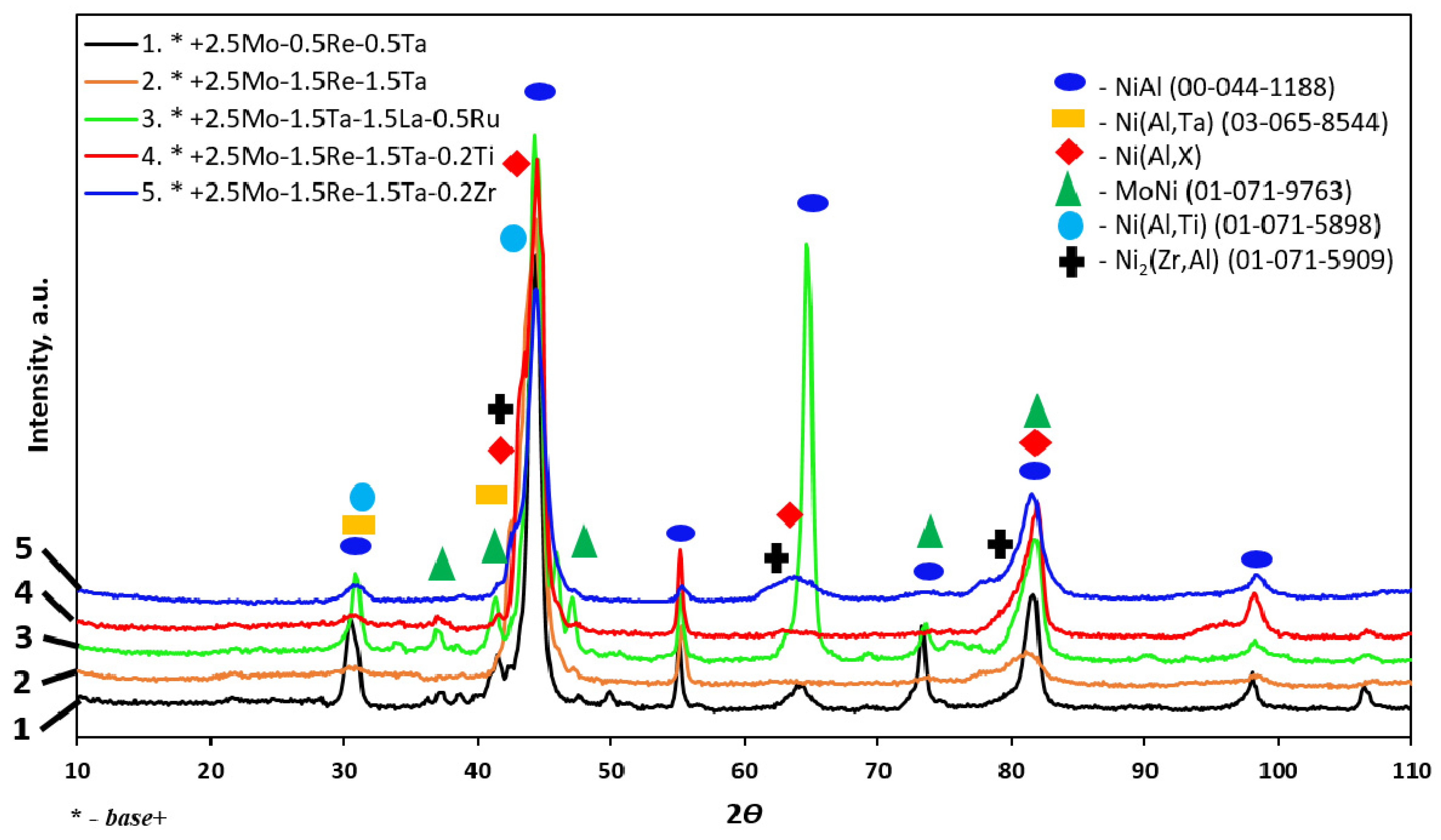
Figure 2 and
Table 4 show the phase composition of the synthesized alloys. β-NiAl was the major phase. The Ni(Al,Ta) phase was present in alloys 2 and 3 with Ta content up to 1.5%, while alloy 3 contained the MoNi phase. The Ni(Al,Ti) phase was identified in alloy 4 doped with 0.2% Ti, while doping with 0.2% Zr (alloy 5) gave rise to the Ni
2(Zr,Al) phase.
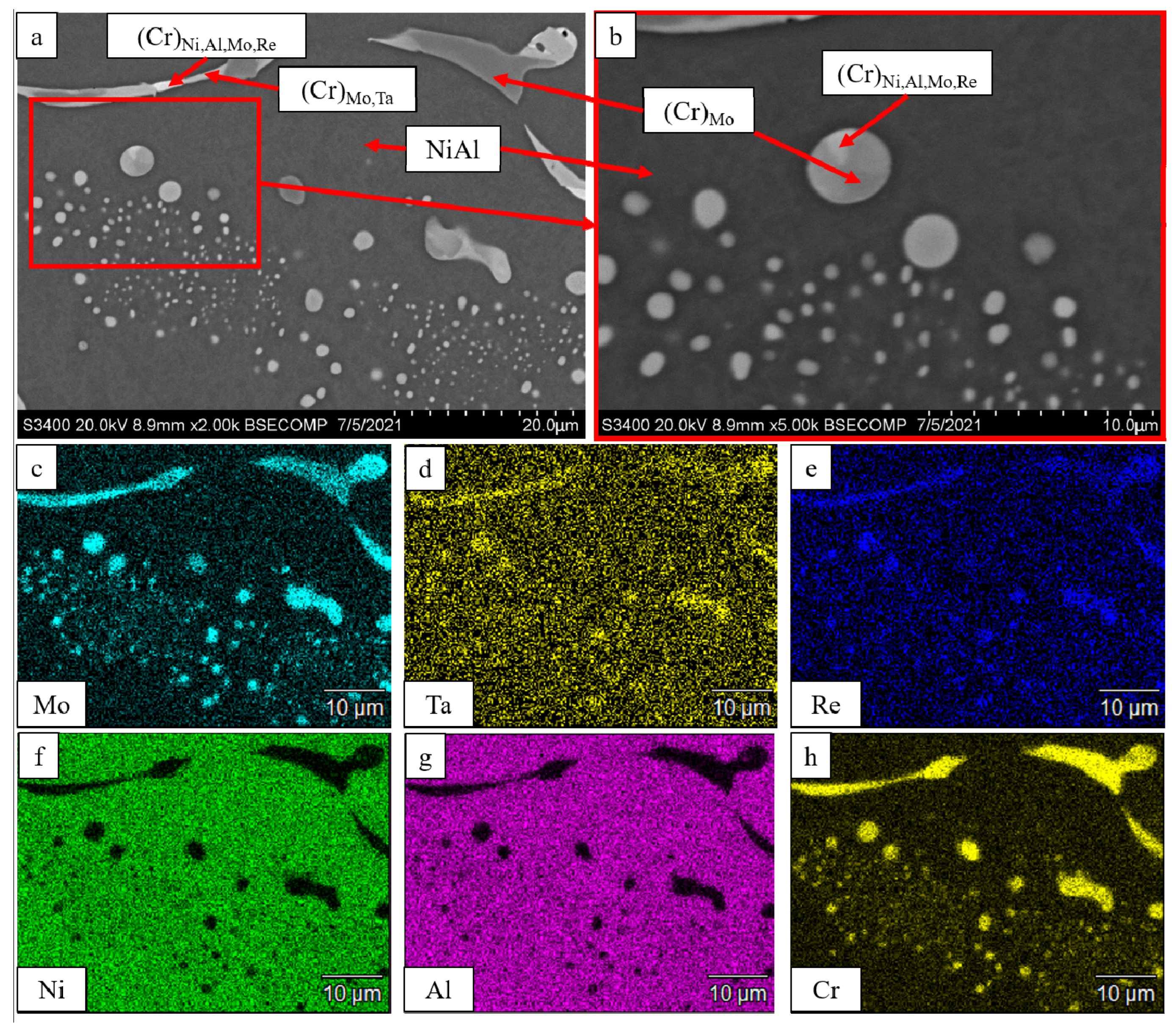
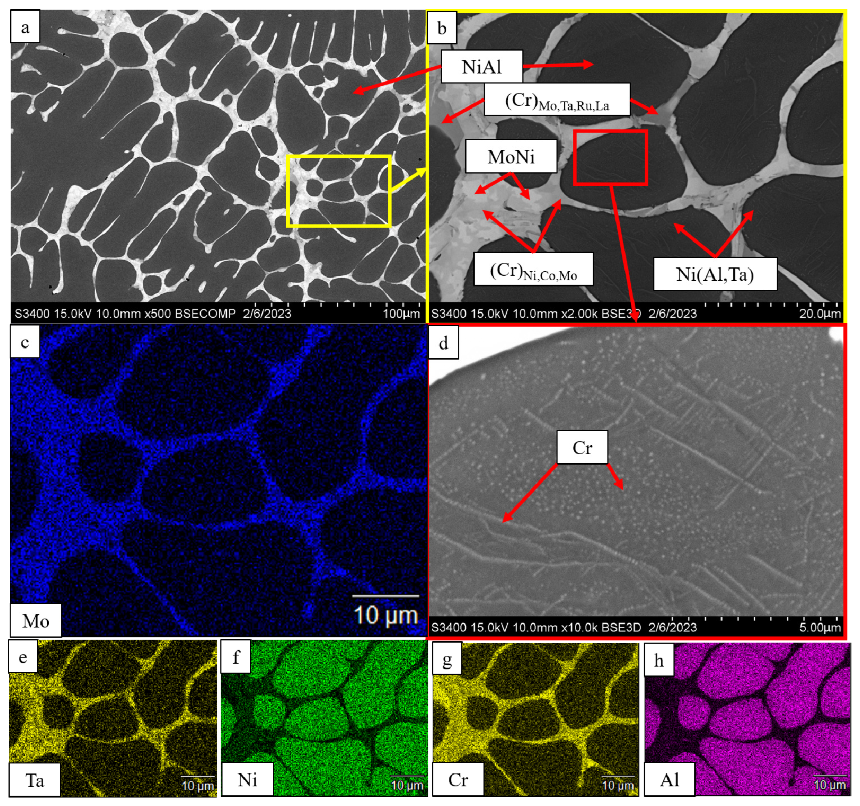
Figure 3 shows that in the case of complex doping of an alloy with Mo, Re and Ta metals, inclusions based on solid solution of chromium of different compositions were formed in the
β-NiAl matrix. For the
base+2.5Mo-0.5Re-0.5Ta composition, globular micron- and submicron-sized inclusions based on solid solution of chromium reside inside
β-NiAl grains. Inclusions 2–8 µm thick with compositions (Cr)
Ni,Al,Mo,Re, (Cr)
Mo,Ta and (Cr)
Mo were formed in the intergrain space.
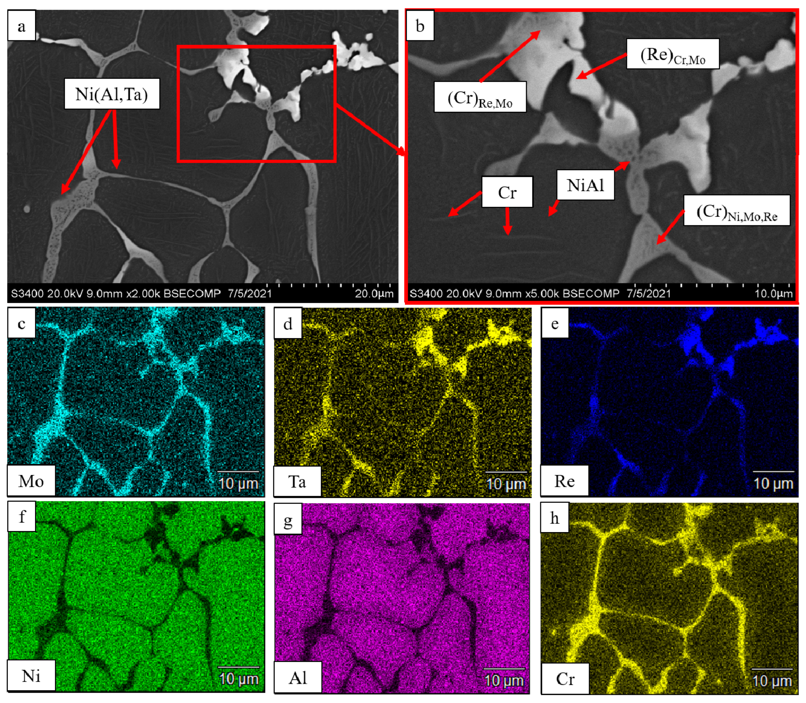
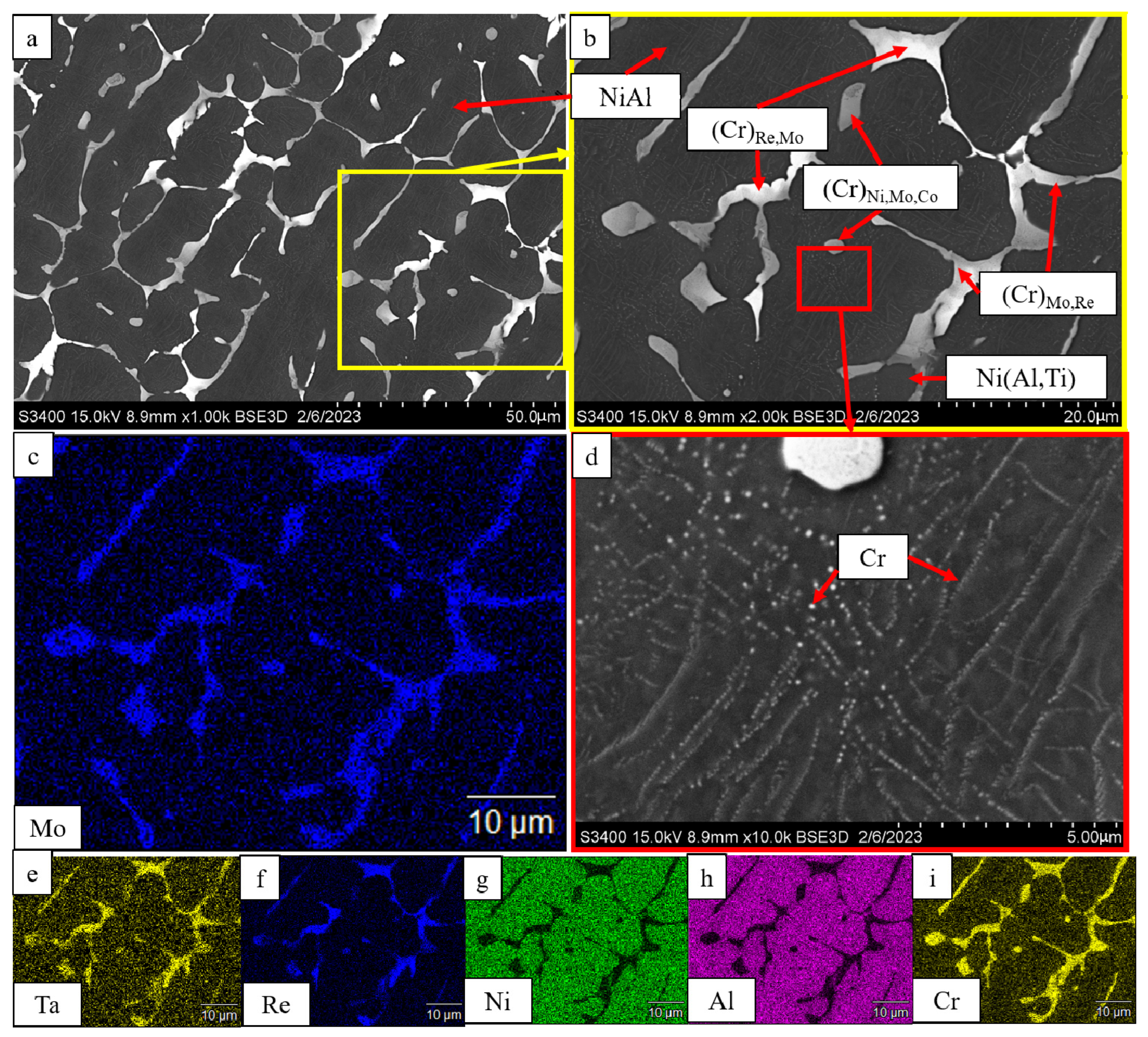
As Ta and Re concentrations were increased to 1.5%, the (
base+2.5%Mo-1.5%Re-1.5%Ta) alloy acquired a well-defined mesh structure (
Figure 4). Cr- and Re-based solid solutions were contained within intergrain interlayers. The Ni(Al,Ta) phase was located at grain boundaries between the solid solution and the NiAl matrix. Submicron-sized NiAl precipitates were detected inside the interdendritic layers. As demonstrated by Aheiev et al. [
31], tantalum localization along the boundaries of the major phase grains had a positive effect on strength properties and increased plastic strain at room temperature. Stringed precipitates of α-Cr were also revealed in the NiAl matrix.
In the
base+2.5%Mo-1.5%Ta-1.5%La-0.5%Ru alloy (
Figure 5), a multicomponent eutectic system was formed between dendrite branches. MoNi precipitates resided in the center of the intergrain space. The (Cr)
Ni,Co,Mo solid solution was formed around the MoNi phase. Furthermore, the intergrain space hosted a chromium-based solid solution with dissolved Mo, Ta, Ru and La. Identically to the alloy described previously, the Ni(Al,Ta) intermetallic phase was formed at grain boundaries, and stringed inclusions of α-Cr were observed inside the grain.
Additional doping of the alloy with titanium (
base+2.5%Mo-1.5%Re-1.5%Ta-0.2%Ti) did not qualitatively alter the structure (
Figure 6). The Ni(Al,Ti) was formed at grain boundaries, which increased plastic strain resistance and strength of the alloy as it can be seen in
Table 5. The interdendritic layer hosted the chromium-based solid solution, while the matrix contained stringed inclusions of α-Cr.
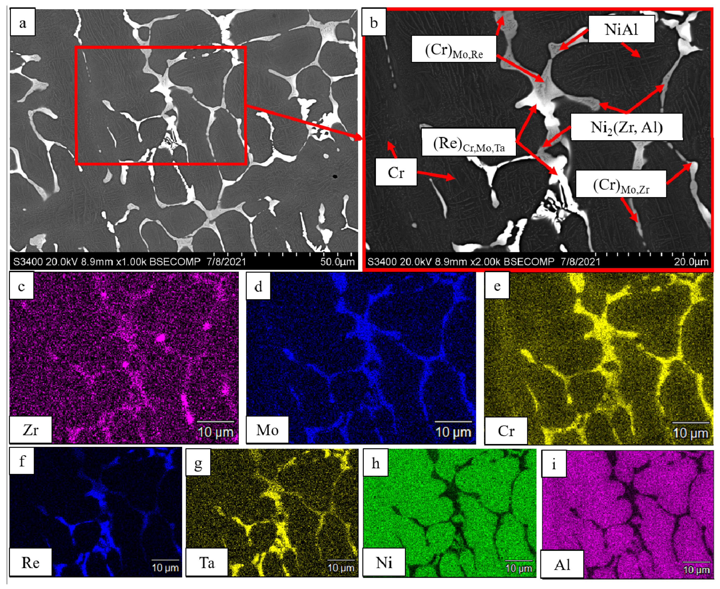
In a similar manner, doping the alloy with 0.2% Zr (
base+2.5%Mo-1.5%Re-1.5%Ta-0.2%Zr) resulted in the precipitation of the Ni
2(Zr,Al) phase (
Figure 7). The intergrain layers were formed by solid solution based on chromium and rhenium with NiAl precipitates. Microprobe analysis showed that tantalum was a component of the (Re)
Cr,Mo,Ta solid solution.
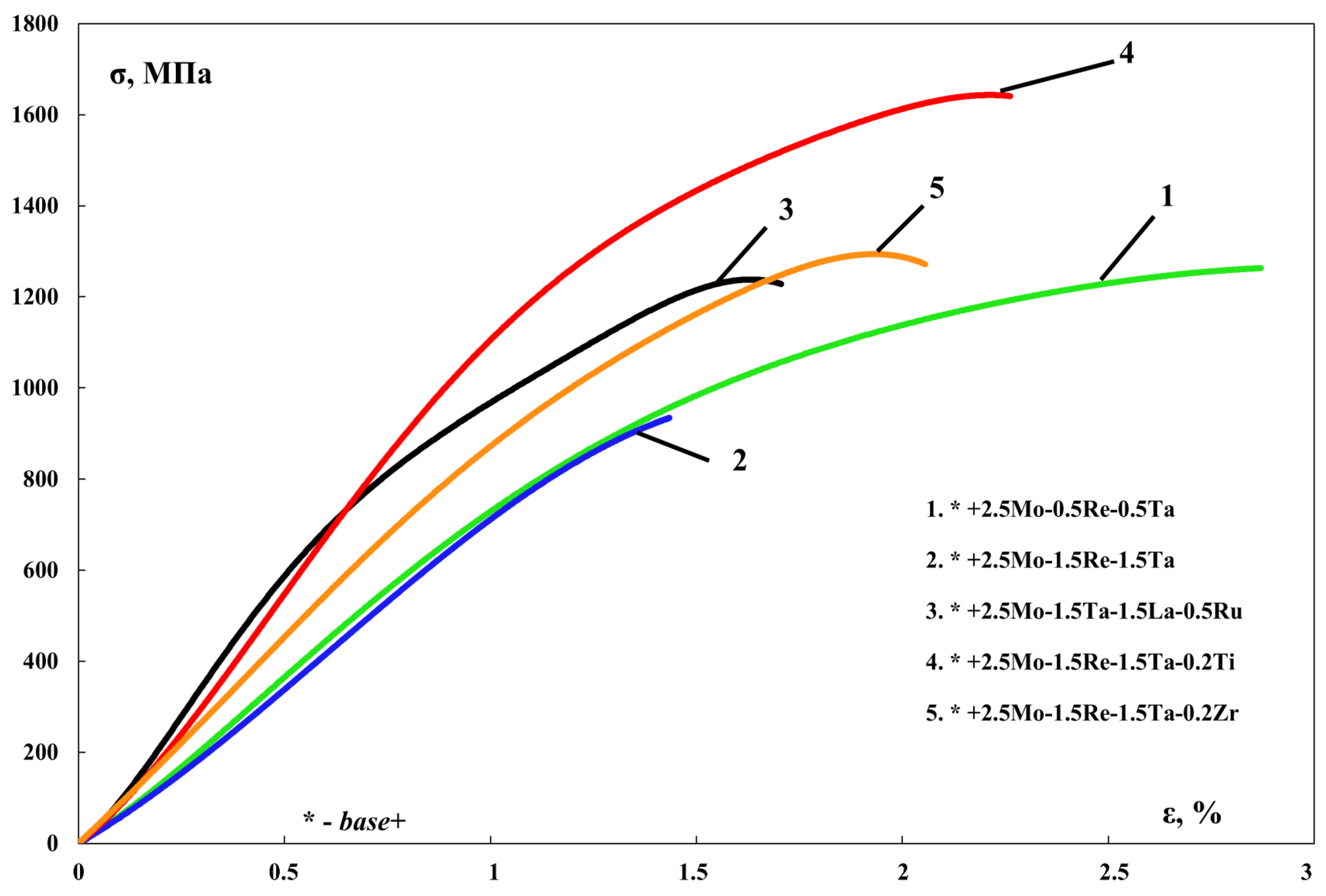
Table 5 lists the results of measuring the mechanical properties of cast SHS alloys. One can see that the
base+2.5%Mo-1.5%Re-1.5%Ta-0.2%Ti alloy had the best combination of properties (hardness, strength, the yield point and residual strain): σ
ucs = 1644 ± 30 MPa, σ
ys = 1518 ± 25 MPa (
Figure 8).
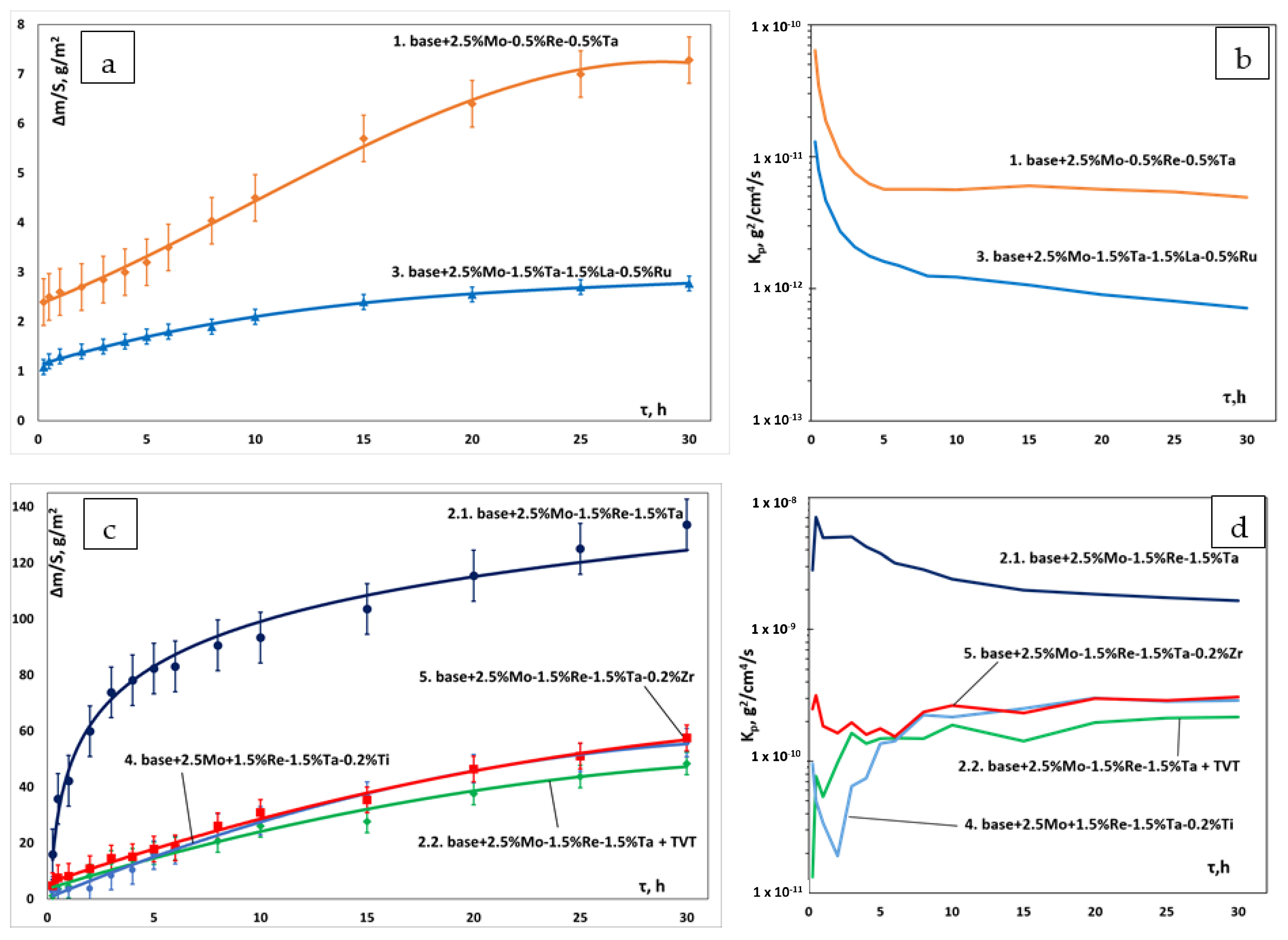
In order to study the effect of complex doping on the high-temperature oxidation resistance of the alloys, air annealing at 1150 °C was performed during 30 h; the samples were periodically weighed. When investigating the oxidative resistance for the previous series of alloys, Aheiev et al. [
31] demonstrated that a multilayer oxide film was formed in the alloys characterized by the greatest weight gain. The transitional MeN-Me layer mainly consisted of nitrides due to the high content of dissolved nitrogen, which diffused from the alloy along grain boundaries to interact with aluminum, thus disrupting alloy integrity. Therefore, additional vacuum annealing (TVT at 700 °C during 2 h) was carried out in this study for the
base+2.5Mo-1.5%Re-1.5%Ta alloy as an example.
Table 6 lists the weight gain values after oxidative annealing at 1150 °C during 30 h, as well as the kinetic regression equations corresponding to the oxidation curves shown in
Figure 9.
Figure 9b,d shows the parabolic rate constant determined for each composition. The parabolic rate constant
kp was measured by the method as follows (2). Line 2.2 corresponds to the sample subjected to additional vacuum annealing. The parabolic rate constant of oxidation is shown in
Figure 9b,d. The parabolic rate constant was measured as follows:
where: ∆
m is the mass change;
S is the surface area;
t is time.
For samples 1, 2.2, 3, 4 and 5, the shape of the curves corresponds to the parabolic law of oxidation: a continuous barrier oxide layer was formed within the first few hours of oxidation, inhibiting oxygen diffusion into the sample. The oxidation curve of sample 2.1 is fitted by logarithmic law (local phase segregation takes place due to the internal stress emerging during thermal cycling).
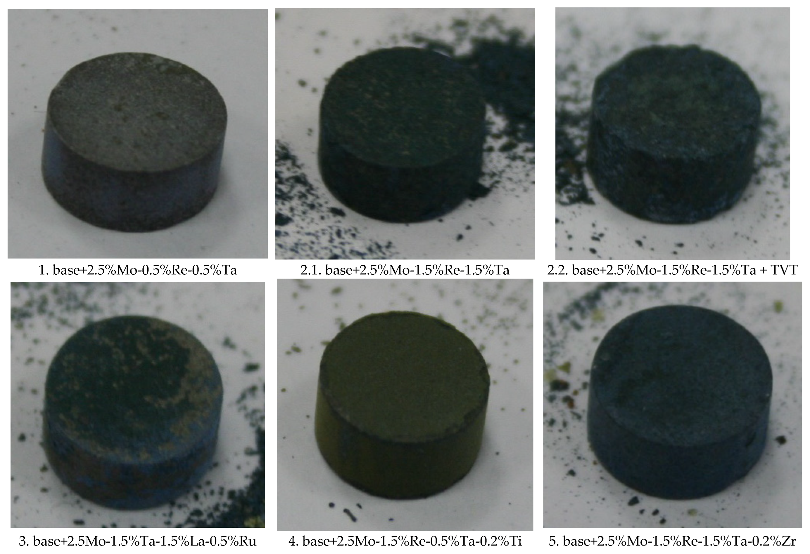
Figure 10 shows the appearance of the oxidized samples. Each alloy had its own hue and certain topology. Signs of physical degradation were observed for none of the samples.
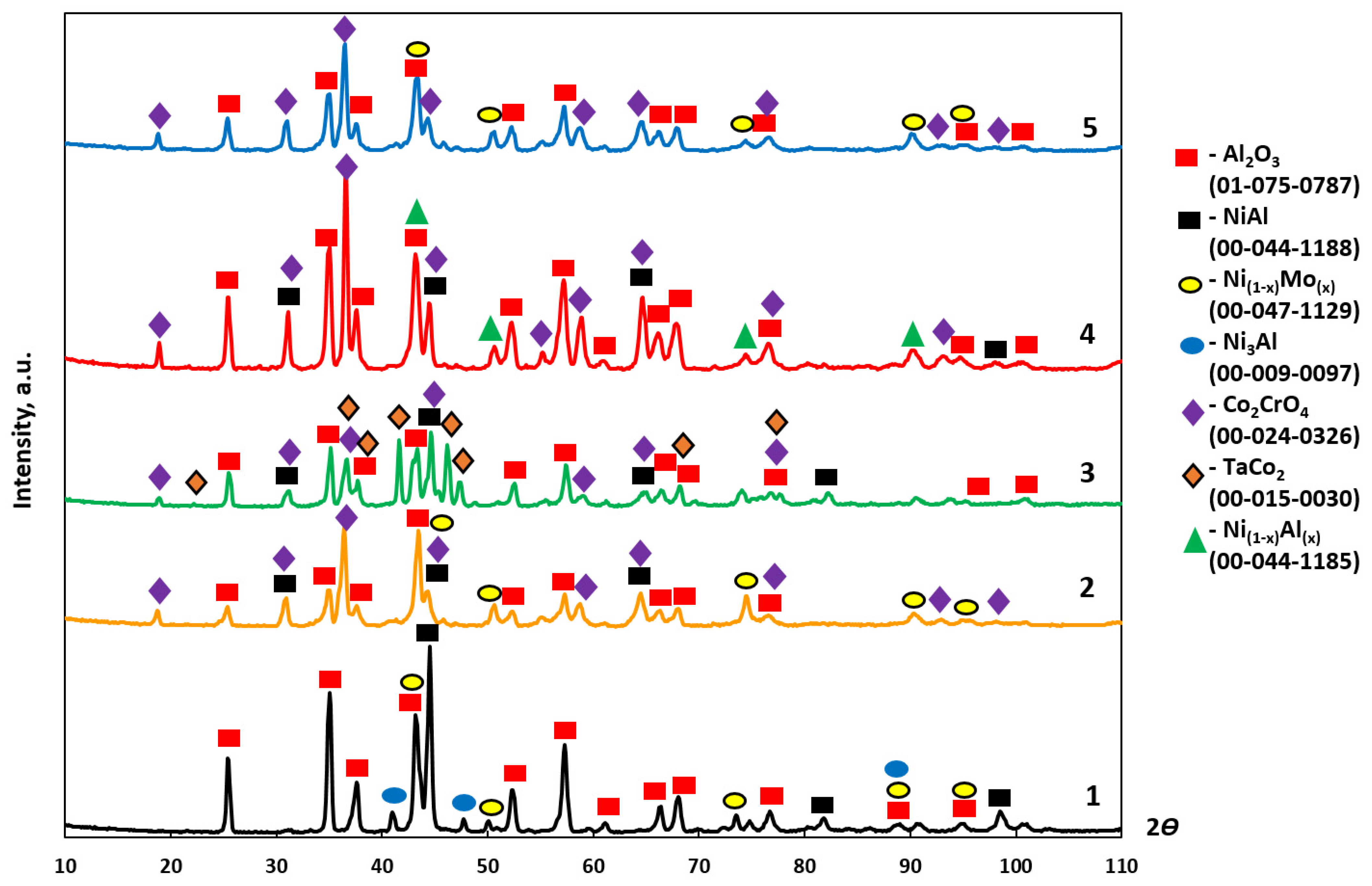
Table 7 summarizes the results of XRD analysis of the oxidized layer of the samples; the XRD spectra are shown in
Figure 11. Al
2O
3 was the main oxidation product. Co
2CrO
4 was the next phase (according to its weight fraction). Lines belonging to NiAl were also present in the XRD spectra along with those corresponding to oxides. Traces of the Ni
3AlN phase were detected among the oxidation products with composition 1.
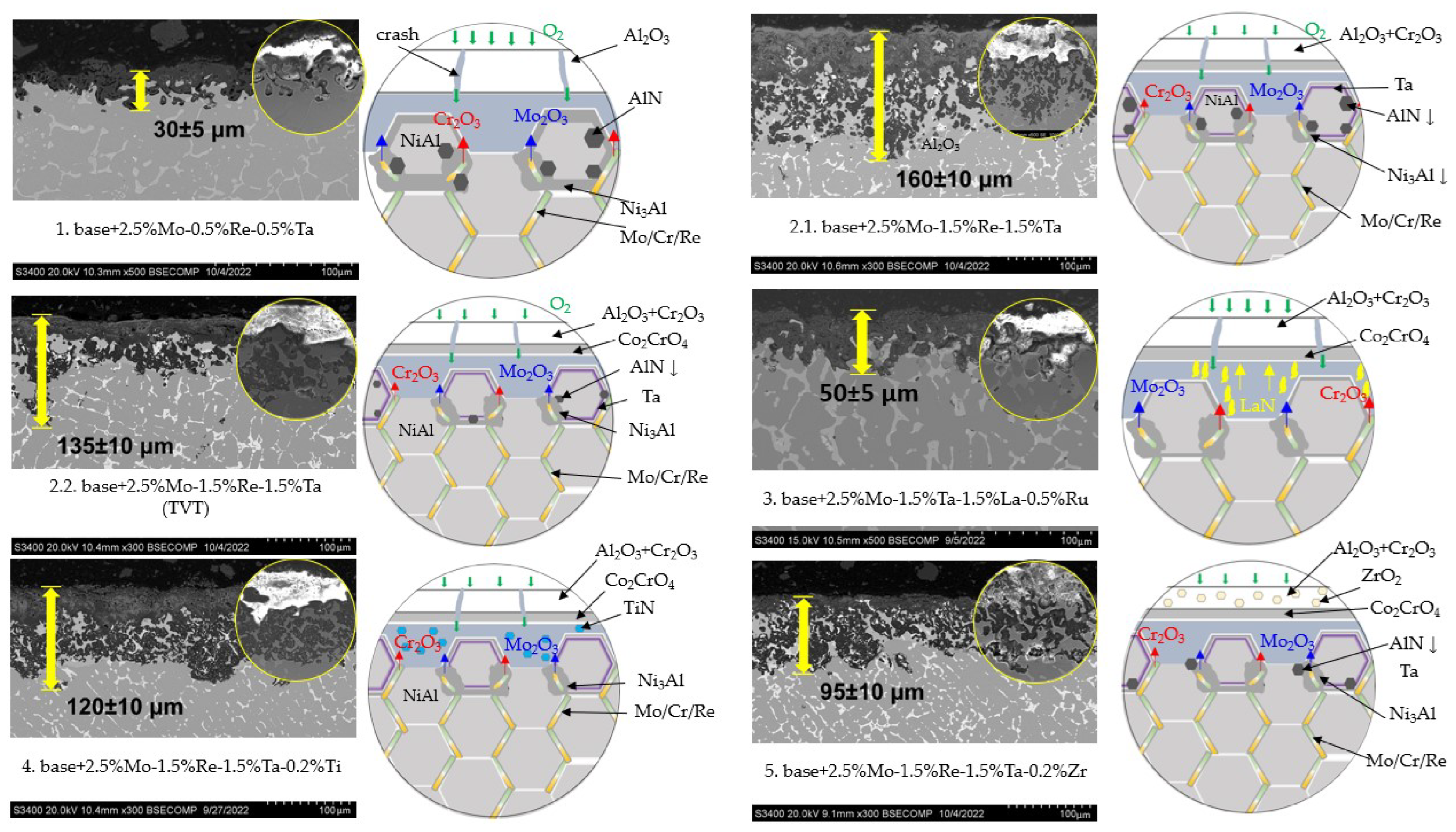
Figure 12 shows the microstructures of the samples after high-temperature oxidation resistance tests, the size of oxide and transitional layers being specified. One can see that in all the cases, a continuous oxide film impeding diffusion-controlled penetration of oxygen and nitrogen to the alloy was formed at the initial oxidation stage. A transitional MeN-Me layer was formed in the alloys with increased Re content (1.5%), being indicative of nitrogen diffusion in the alloy.
A thorough analysis of the oxidation mechanism is provided in
Figure 13,
Figure 14,
Figure 15,
Figure 16,
Figure 17,
Figure 18,
Figure 19,
Figure 20,
Figure 21,
Figure 22 and
Figure 23. Alloy 2.2 containing Mo, Re and Ta microdopants was chosen as an example of the positive effect of thermo-vacuum treatment of cast SHS alloys on the microstructure after high-temperature oxidation resistance testing; its analysis is provided in
Figure 15.
The top dense oxidized layer on the
base+2.5%Mo-0.5%Re-0.5%Ta sample with composition 1 consisted of Al
2O
3, which was a distinctive feature of this alloy compared to other ones. The Al
2O
3 alloy was formed during the initial oxidation period and impeded oxygen diffusion into the sample. The MoNi phase and the chromium-based solid solution resided in the oxidized layer as globular inclusions and around non-oxidized NiAl regions (
Figure 13). Because of the small dopant concentration in the alloy with composition 1, the sample had a structure with a low content of solid-solution inclusions in the intergrain space. This factor could restrain oxygen and nitrogen diffusion at grain boundaries during the initial oxidation period, contributing to the formation of solid Al
2O
3 film, as well as preventing nitrogen diffusion and the formation of aluminum nitride. Meanwhile, nitrogen dissolved in the alloy entered the reaction yielding Ni
3AlN nitride perovskite.
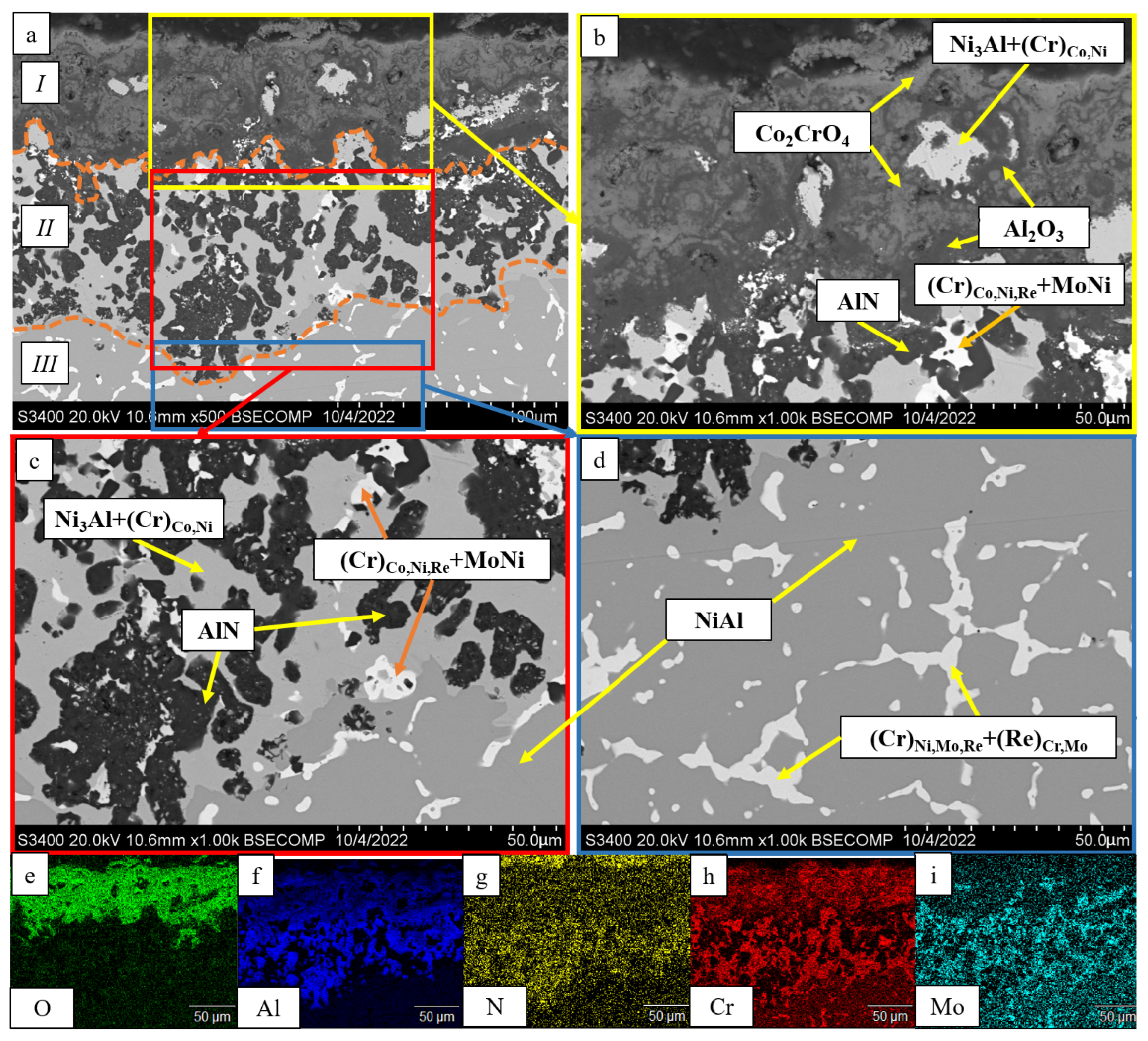
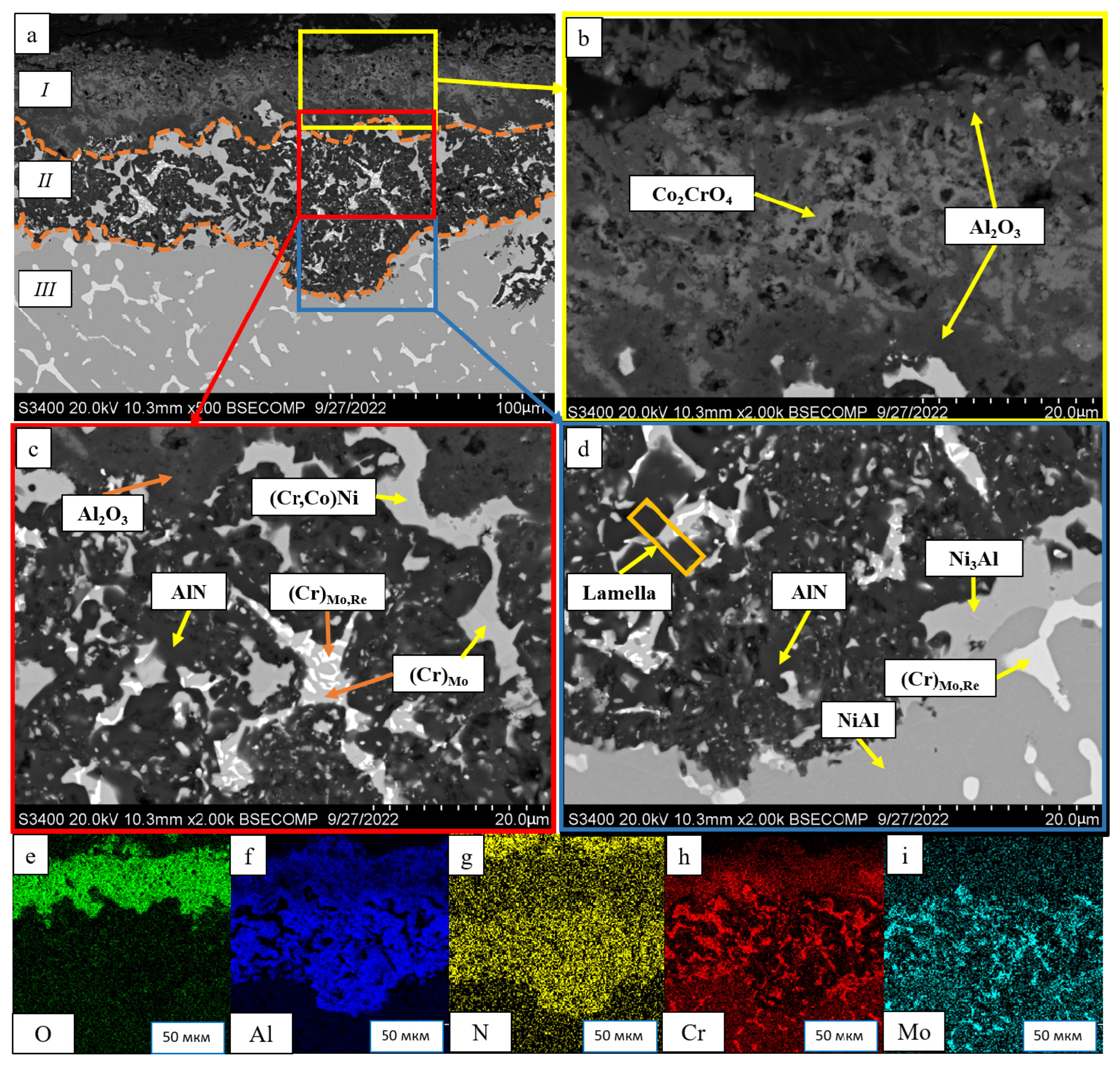
After oxidative annealing, the
base+2.5%Mo-1.5%Re-1.5%Ta alloy with composition 2 (characterized by increased Re and Ta contents) had a multilayer surface structure. According to the pattern of oxygen and nitrogen distribution, the oxide layer could be subdivided into three sublayers:
I—the continuous Al
2O
3 oxide film with a non-uniform distribution of Co
2CrO
4 spinel inclusions;
II—the transitional MeN-Me layer containing AlN inclusions; and
III—the metal layer with sparse inclusions of AlN (
Figure 14). The oxide layer was formed at the initial stage during the formation of chromium, cobalt and aluminum oxides and Co
2CrO
4 spinel. The Co
2CrO
4 phase resulted from interaction between chromium and cobalt oxides. Spinel was composed of coarse grains with defects through which surface diffusion of oxygen and nitrogen into the sample could occur. In turn, the formation of Al
2O
3 reduced the partial pressure of oxygen and impeded spinel formation [
34]. A continuous Al
2O
3 layer was located at the boundary between sublayers
I and
II, being responsible for the enhancement of oxidation resistance. Sublayer
I contained, along with oxides, a small amount of the Ni
3Al phase that had been formed during the oxidation of aluminum. In the transitional MeN-Me layer, nitrogen reacted with aluminum to yield AlN nitrides, which also depleted NiAl to Ni
3Al. Along with Ni
3Al, the interaction between nitrogen and aluminum contributed to the formation of the MoNi intermetallic phase [
34].
In order to assess the effect of thermo-vacuum treatment on high-temperature oxidation resistance, we analyzed the microstructure of the oxidized alloy with composition 2 that had undergone vacuum annealing (
Figure 15).
Figure 12 (No. 2.2:
base+2.5%Mo-1.5%Re-1.5%Ta+TVT) showed that the maximum thickness of the alloy after vacuum annealing was lower (135 µm) than that for the sample not subjected to TVT (160 µm). The average thickness of the oxidized layer for the sample after TVT was 50 µm. Weight gain was also approximately threefold lower (
Table 6), thus proving the positive effect of vacuum annealing. Not only did nitride formation during the initial oxidation stage disrupt the integrity of ingots, but it also impeded the formation of the Al
2O
3 barrier oxide layer [
35,
36]. The lower content of nitrogen impurity inhibited the formation of nitrides in the alloy, thus increasing its oxidation resistance. An analysis of the alloy microstructure after TVT showed that the structure and the mechanism of formation of the oxidized layer were similar to those for the alloy not subjected to TVT: three sublayers were formed, NiAl became Al-depleted, and the Ni
3Al and MoNi phases were precipitated [
36].
Figure 16 shows the structure of the oxidized surface of the sample with composition 3 (
base+2.5%Mo-1.5%Ta-1.5%La-0.5%Ru). The content of Co
2CrO
4 spinel in this sample was significantly lower (13.4 wt.%) (
Table 6). The oxidized layer contained Al
2O
3 with chaotic inclusions of the Co
2CrO
4 phase. A distinctive feature of this alloy is that the Co
2CrO
4 phase was located under the Al
2O
3 layer [
37,
38]. Globular inclusions of chromium and unreacted regions of the TaCo
2 phase and (Cr)
Ni,Mo solid solution were detected in the oxidized layer. This sample did not contain the Ni
3Al phase; AlN inclusions resided at the NiAl/(Cr)
Ni,Mo interface.
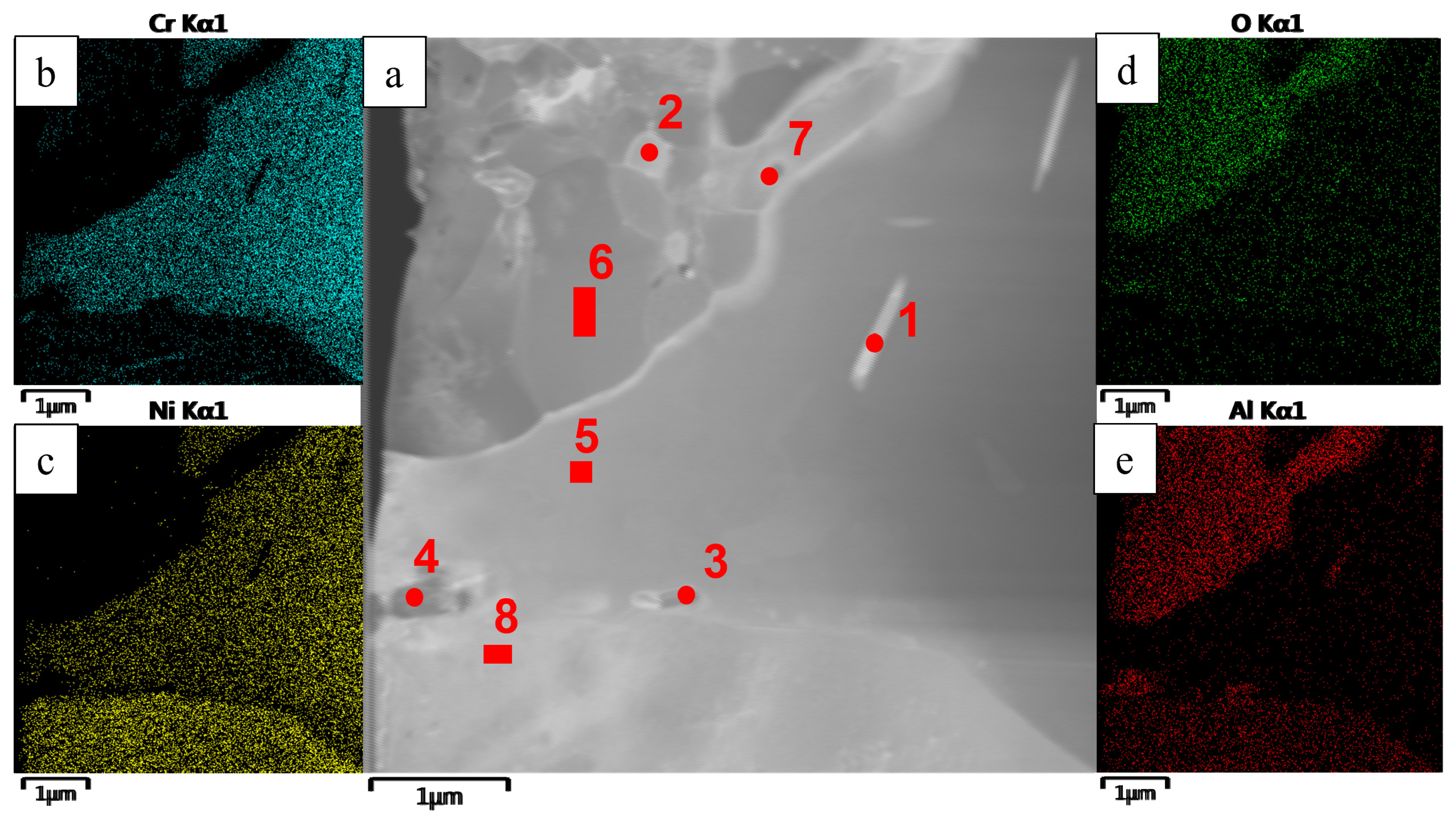
A detailed analysis of the oxidized layer of the
base+2.5%Mo-1.5%Ta-1.5%La-0.5%Ru sample was carried out by transmission electron microscopy (TEM). A lamella cut from a cross-section of the metal/oxidized layer interface by FIB was used as a study object (the lamella cutting site is indicated in
Figure 16).
Figure 17,
Figure 18 and
Figure 19 and
Table 8 show the images of the lamella and the EDS maps of distribution of the respective elements. The near-surface layer consisted of Al
2O
3 (
Figure 17, spectra 2 and 6), which was an efficient barrier blocking oxygen and nitrogen diffusion deep inside the sample. Nanosized inclusions of Co
2CrO
4 spinel with fcc crystal lattice (space group Fd3m) and lattice parameter
a = 8.131 Å were arranged along the boundaries of Al
2O
3 grains (
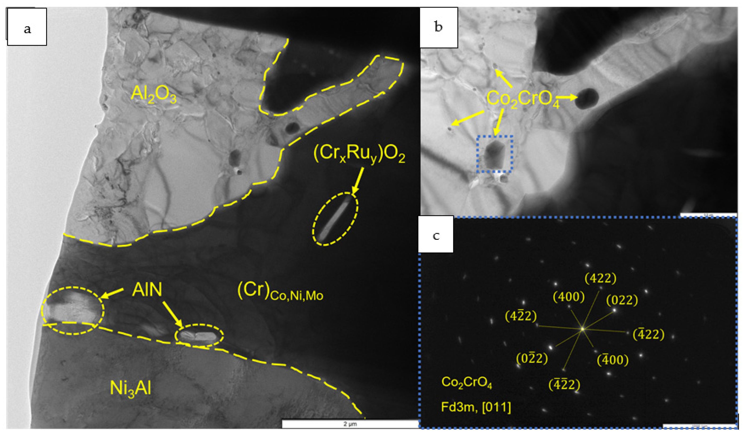
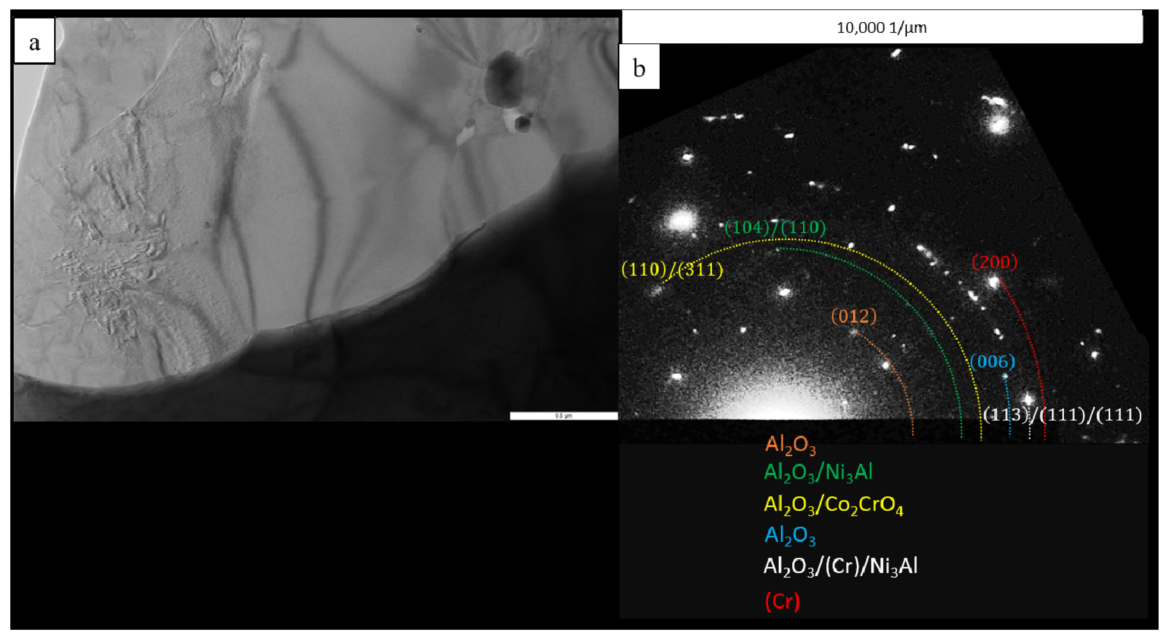
Figure 18). As found earlier, this phase present as coarse grains negatively affected the high-temperature oxidation resistance of alloys, since they caused the formation of cracks acting as oxygen diffusion channels. However, in the
base+2.5%Mo-1.5%Ta-1.5%La-0.5%Ru alloy, the Co
2CrO
4 phase consisted of uniformly distributed particles sized up to 100 nm and did not cause cracking of the oxide layer. The electron diffraction data recorded for the surface region of the oxidized layer proved that nanosized Co
2CrO
4 spinel crystals were present (
Figure 18). Under the layer based on Al
2O
3 and Co
2CrO
4, there was an interlayer consisting of coarse grains of chromium-based solid solution. It was shown by EDS that Co, Ni and Mo (15–20 wt.%) were dissolved in this phase. The substrate region immediately adjacent to the oxidized layer consisted of the Ni
3Al phase formed via Ni depletion in NiAl (
Figure 17 and
Figure 18, spectrum 8). Lamellar AlN inclusions sized <1 µm (
Figure 17 and
Figure 18, spectra 3 and 4) were detected at the Ni
3Al/MoNi interface (
Figure 17 and
Figure 18, spectra 3 and 4). They were formed via the diffusion of nitrogen dissolved in the alloy along grain boundaries towards the sample surface and interaction with aluminum.
Ru is an efficient getter of oxygen and nitrogen [
2]. Doping the alloy with this element significantly reduced the weight gain by the samples in oxidative testing. It is most likely that as oxygen diffused deep into the sample, Ru dissolved in the (Cr) phase formed stable complex oxide. The examination of the lamella revealed inclusions of this oxide. The small size of inclusions did not allow us to accurately identify the phase according to the electron diffraction data (
Figure 18). However, relying on the chemical composition of this region, a hypothesis can be put forward that this oxide was chromium–ruthenium double oxide (Cr
xRu
y)O
2.
Similar to alloy 2, the oxidized surface of the alloy with composition 4 (
base+2.5%Mo-1.5%Re-1.5%Ta-0.2%Ti) (
Figure 20) consisted of three layers. The top 40-µm-thick oxide layer composed of Al
2O
3 and Co
2CrO
4 spinel was characterized by low density and high pore content. Below, there was a thin continuous sublayer (5 µm) composed of Al
2O
3, which impeded oxygen penetration inside the material. A thick layer (up to 100 µm) based on AlN with inclusions of chromium-containing phases (Cr,Co)Ni, (Cr)
MoRe and (Cr)
Mo lay at the boundary with the substrate.
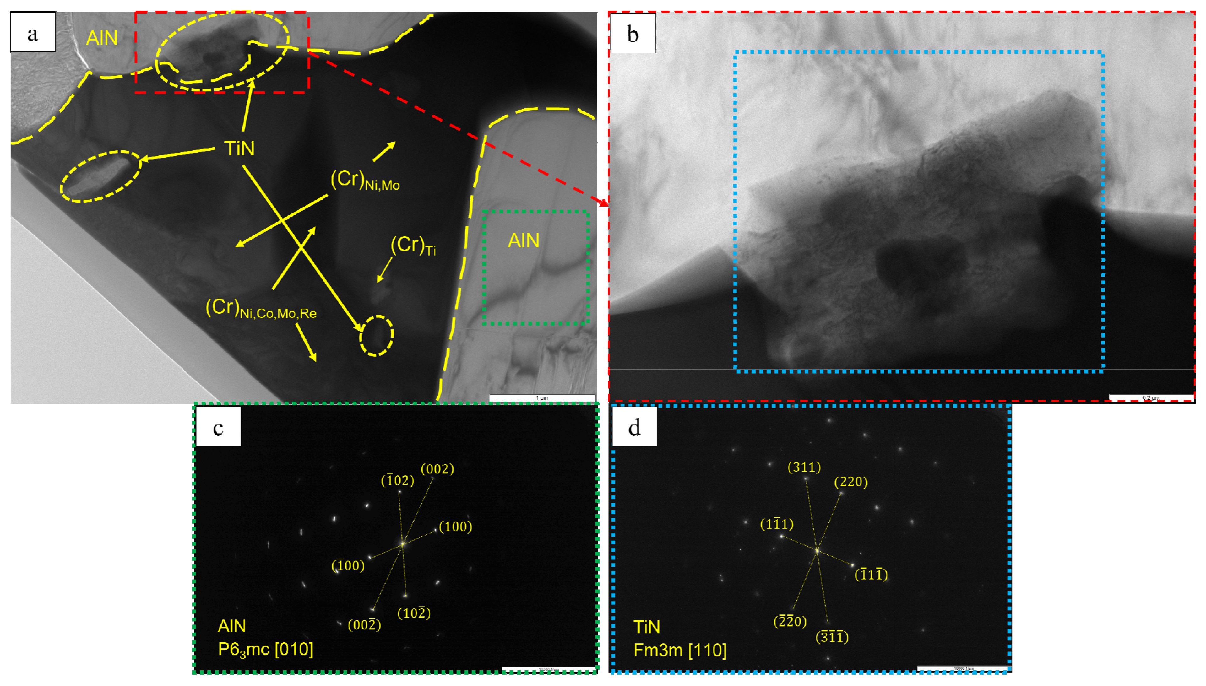
A lamella cut from the transverse section of the transitional MeN-Me layer in which nitrides are formed was studied by TEM (the lamella cutting site is shown in
Figure 20). The structure of the lamella is presented in
Figure 21 and
Figure 22 and
Table 9.
Figure 21 also shows the EDS element distribution maps, where Ti inclusions were detected (spectra 1, 2 and 9). Aluminum nitride AlN, having the hexagonal crystal lattice (space group P6
3mc) and lattice parameters
a = 3.083 Å,
c = 5.001 Å, was the major phase of the transitional layer (
Figure 21, spectra 3, 7 and 8). Nitrogen diffusing along boundaries of the grains of the loose Al
2O
3 + Co
2CrO
4 oxide layer into the metal, as well as nitrogen impurity dissolved in the alloy, reacted with aluminum contained in the matrix to give rise to AlN. Local Al depletion in the alloy yielded chromium (Cr)-based solid solution containing Ti, Co, Ni, Mo and Re at concentrations ranging from 7 to 25 wt.% (
Figure 21, spectra 1, 2, 4, 5 and 6).
Submicron-sized inclusions of the fcc phase TiN with lattice parameter
a = 4.205 Å were detected at the boundaries of the grains of chromium (Cr)-based solid solution and the Cr/aluminum nitride (AlN) interface (
Figure 22). Not only did the resulting TiN bind nitrogen dissolve in the alloy, thus reducing its concentration (
Table 3), but it also enhanced the activity of aluminum diffusing towards the surface, which contributed to the formation of a dense oxide layer [
33,
39].
The oxidized layer on the surface of the
base+2.5%Mo-1.5%Re-1.5%Ta-0.2%Zr alloy had a structure identical to those of alloys 2 and 4. Its average thickness was 95 µm. A loose layer composed of a mixture of the Al
2O
3 + Co
2CrO
4 phases and a dense interlayer consisting of Al
2O
3 were formed on the surface (
Figure 23). The significant high-temperature oxidation resistance was presumably ensured by nanosized inclusions of the Zr
5Al
3O
0.5 phase as demonstrated earlier [
32] for nickel monoaluminide doped with 0.5% Zr. The MoNi phase and (Cr)
Re,Zr, (Cr)
Re and (Cr)
Co,Ni solid solutions were observed in the transitional layer. The metal layer of the NiAl matrix also contained AlN inclusions, being indicative of nitrogen diffusion along grain boundaries.


 ,
, 


