Article

Construction of a ZnO Heterogeneous Structure Using Co3O4 as a Co-Catalyst to Enhance Photoelectrochemical Performance

by
Aiymkul A. Markhabayeva
*,
Zhanar K. Kalkozova
,
Renata Nemkayeva
,
Yerassyl Yerlanuly
,
Assiya S. Anarova
,
Malika A. Tulegenova
,
Aida T. Tulegenova
and
Khabibulla A. Abdullin
Faculty of Physics and Technology, Al Farabi Kazakh National University, 71 Al-Farabi Avenue, Almaty 050040, Kazakhstan
*
Author to whom correspondence should be addressed.
Materials 2024, 17(1), 146; https://doi.org/10.3390/ma17010146
Submission received: 2 November 2023 / Revised: 15 December 2023 / Accepted: 19 December 2023 / Published: 27 December 2023
(This article belongs to the Special Issue Advanced Materials and Methods for Heterogeneous Catalysis)

Abstract

:
Recently, heterostructured photocatalysts have gained significant attention in the field of photocatalysis due to their superior properties compared to single photocatalysts. One of the key advantages of heterostructured photocatalysts is their ability to enhance charge separation and broaden the absorption spectrum, thereby improving photocatalytic efficiency. Zinc oxide is a widely used n-type semiconductor with a proper photoelectrochemical activity. In this study, zinc oxide nanorod arrays were synthesized, and then the surfaces of ZnO nanorods were modified with the p-type semiconductor Co3O4 to create a p–n junction heterostructure. A significant increase in the photocurrent for the ZnO/Co3O4 composite, of 4.3 times, was found compared to pure ZnO. The dependence of the photocurrent on the morphology of the ZnO/Co3O4 composite allows for optimization of the morphology of the ZnO nanorod array to achieve improved photoelectrochemical performance. The results showed that the ZnO/Co3O4 heterostructure exhibited a photocurrent density of 3.46 mA/cm2, while bare ZnO demonstrated a photocurrent density of 0.8 mA/cm2 at 1.23 V. The results of this study provide a better understanding of the mechanism of charge separation and transfer in the heterostructural ZnO/Co3O4 photocatalytic system. Furthermore, the results will be useful for the design and optimization of photocatalytic systems for water splitting and other applications.

1. Introduction

In recent years, there has been a growing interest in alternative energy sources to compensate for diminishing fossil fuel resources. Harnessing solar energy is a promising way to counteract the energy crisis [1]. Efficient photoelectrochemical (PEC) water splitting systems offer a potential solution for the conversion of solar energy into other forms of energy. Effective water splitting technology requires a high light absorption coefficient and stable photocatalysts with appropriate bandgap energy. The energy levels of the conduction band (CB) in semiconductors need to be situated at a lower value than the hydrogen reduction potential (0 V vs. NHE), whereas the valence band (VB) should be at a higher energy level than the oxidation potential of oxygen (1.23 V vs. NHE). However, many metal oxide semiconductors that can absorb visible light and have a narrow bandgap of less than 2 eV do not have suitable VB and CB positions for water splitting. To overcome this, various techniques have been employed, such as doping with extraneous atoms to increase the number of states near the CB or VB, altering the particle size, using combinations of materials for efficient energy or electron transfer to absorb light with different energies, or employing plasmonic excitation to enhance the light absorption and photocatalytic efficiency [2,3,4,5].
Among the metal oxides, ZnO, TiO2 [6,7], and ZrO2 exhibit both conduction and valence band energies suitable for water splitting [8,9]. In particular, ZnO is an n-type direct-gap semiconductor with a band gap of ~3.3 eV at room temperature. The value of optical transmission is 85–90% in the range of 400–700 nm for ZnO thin films [10,11]. Due to its low toxicity and high electronic conductivity, it has been extensively studied for various optoelectronic applications [12], including solar cells, gas sensors, and phosphors. In addition, ZnO exhibits better light absorption than TiO2, because its refractive index is lower (2.0) than that of TiO2 (2.5–2.7), resulting in increased transparency and reduced light scattering.
However, zinc oxide is susceptible to photocorrosion in aqueous and acidic electrolytes and dissolves to form Zn(OH)2 [13]. Despite this limitation, experimental results have shown that ZnO actually exhibits higher photocatalytic activity than TiO2 and other semiconductor catalysts, such as CdS, WO3, Fe2O3, SnO2, ZrO2, and GaSe [14], especially in the degradation of dyes in aqueous solution [15,16,17,18,19]. These advantages make it a good candidate for a photoelectrode in photoelectrochemical cells for water oxidation.
Significant research efforts have been dedicated to the exploration of ZnO nanorod arrays, leading to the development of diverse device structures. This is evident in various reviews [20,21,22]. The appeal of such arrays lies in their facile synthesis, high crystallinity, excellent electrical properties, and substantial specific area. Noteworthy studies in related areas include an examination of morphological changes in a ZnO nanorod array with cobalt oxide particles, both pre- and post-photoelectrochemical (PEC) measurements [23]. Additionally, research, such as [24], has delved into variations in photoelectric properties in Co3O4/ZnO samples with different concentrations of the cobalt precursor. Another study, [25], focused on synthesizing ZnO/Co3O4 nanoparticles with varying cobalt contents. Considering these factors, the investigation of the photocatalytic properties of ZnO/Co3O4 structures for water decomposition emerges as a highly relevant and unexplored avenue in the existing body of literature.
The combination of ZnO with Co3O4, a p-type semiconductor with a band gap of 2.1 eV and known surface catalytic activity, showed improved photoelectrochemical performance [26] and oxygen evolution reaction [27], by separating charge carriers at the p–n interface [28,29]. Based on our previous experience [30], the formation of a WO3/Co3O4 p–n type heterojunction reduced the recombination of photocatalytic charges and enhanced the light absorption capabilities, resulting in a photocurrent 20 times higher than that of pristine WO3.
In this study, we synthesized a photocatalytic composite consisting of a ZnO nanorod array and a Co3O4 nanoparticle cocatalyst. A significant finding revealed a fourfold enhancement in the photocurrent within the ZnO/Co3O4 system when compared to ZnO alone. Furthermore, the photocurrent’s correlation with the size of ZnO nanorods exhibits a non-monotonic pattern, suggesting the potential for maximizing photocurrent and optimizing photocatalytic properties in the ZnO/Co3O4 system by tailoring the morphology of ZnO nanorod arrays.

2. Experimental Sections

2.1. Chemicals

Zinc acetate dehydrate (99.99%), zinc nitrate hexahydrate (98%), urotropine (99%), cobalt nitrate hexahydrate (99%), sodium sulfide (95%), and hexamethylenetetramine C6H12N4 (99%) were purchased from Sigma Aldrich (St. Louis, MO, USA). High purity water (18.2 MΩ·cm) was supplied via the ARIUM 611 DI water purification system, Sartorius Group (Göttingen, Germany). All reagents were used without purification.

2.2. Synthesis

2.2.1. Spin Coating Technique for Deposition of ZnO Seed Layer

In the initial step, a spin coating technique was employed to deposit thin zinc oxide seed layers on the ITO substrates. Prior to synthesis, glass substrates coated with indium tin oxide (ITO) (resistivity of 10 Ω/cm) were thoroughly cleaned in a washing solution consisting of H2O:H2O2:NH4OH in a ratio of 4:1:1.
The sol was prepared by dissolving 0.4 g of zinc acetate Zn(CH3COO)2 in 10 mL of ethanol (96%) at room temperature. To ensure a clear solution, a few drops of lactic acid C3H6O3 (80%) were added to prevent aggregation. The resulting clear solution was then applied to the surface of the ITO substrate through centrifugation at 1000 rpm for 5 min.
Subsequently, the substrates were then dried at 100 °C for 15 min. A final annealing step was performed at 300 °C for 60 min in a muffle furnace. As a result, thin and transparent ZnO layers were formed on the ITO substrates.

2.2.2. Chemical Bath Deposition of ZnO

ZnO nanorods were synthesized via chemical bath deposition. The second stage of the synthesis was the growth of ZnO nanorods. For this purpose, the substrates coated with seed layers were carefully placed into a beaker containing a solution composed of zinc nitrate, Zn(NO3)2, and hexamethylenetetramine, C6H12N4. The concentration of the solution was systematically varied at 25, 50, and 75 mM.
The beaker was then placed in a water bath and heated to a constant temperature of 90 °C. The reaction was allowed to proceed for 1 h. The substrates were then extracted from the solution, washed with distilled water, and dried at 100 °C. As a result of these procedures, ZnO nanorods were formed on the surface of the ITO substrate, demonstrating the successful outcome of this synthesis process.

2.2.3. Deposition of Cobalt Oxide on the Surface of Zinc Oxide

A spin coating technique was further applied to deposit the cobalt oxide layer on top of the prepared ZnO nanorods. For sol preparation, cobalt nitrate, Co(NO3)2, was dissolved in 10 mL of ethanol at room temperature. ZnO photoelectrodes were fixed on a rotating disk, and then an alcoholic solution of cobalt nitrate was dropped onto the ZnO surface. The concentration of the cobalt solution was 0.007 M. The rotation speed was 1000 revolutions per minute (rpm) so that the solution completely covered the surface. The procedure was repeated three times, after which the samples were dried and then annealed at a temperature of 350 °C for 1 h in air. The rate of temperature increase during the heat treatment was 5 °C per minute.

3. Material Characterization

The film morphology was studied using scanning electron microscopy (SEM) on a Quanta 3D 200i microscope (FEI, Brno, Czech Republic) equipped with an energy dispersive X-ray spectroscopy (EDX) system. The crystal structure of the films was studied using a MiniFlex X-ray diffractometer (Rigaku, Tokyo, Japan). The XPS spectra were obtained using an X-ray photoelectron spectrometer (NEXSA, Thermo Scientific, Waltham, MA, USA). Raman spectra were obtained using a Ntegra Spectra (Solver Spectrum, NT-MDT Co., Ltd., Zelenograd, Russia) spectrometer with 473 nm excitation. Photocurrent measurements were performed using a xenon solar simulator (PLS-SXE300, Perfect light, China) with a 1.5 AM filter and a Corrtest CS310 potentiostat (Corrtest Instruments, China).

4. Photoelectrochemical Measurements

Photoelectrochemical (PEC) measurements including linear sweep voltammetry (LSV) and electrochemical impedance spectroscopy (EIS) were carried out to study the PEC material. Photocurrent measurements were performed using a Xenon solar lamp (AM 1.5 G, 100 mW/cm2), potentiostat, and a quartz cell. All photoelectrochemical and deposition experiments were carried out at room temperature using a standard three-electrode system with a Pt counter electrode and an Ag/AgCl reference electrode. The area of the working photoelectrode was 1 cm2, and the rest of the electrode was covered with epoxy resin. An aqueous solution of electrolyte containing Na2S (0.5 M) and Na2SO3 (0.5 M) was used as the electrolyte. The Nernst equation is used to convert potentials: V R H E = V A g / A g C l + 0.0591 × p H + V A g / A g C l 0 , where VAg/AgCl is the applied potential, V0Ag/AgCl is the standard potential of the Ag/AgCl reference electrode, and pH is basicity or acidity of the electrolyte. The pH of the electrolyte was 8.4. The sample was illuminated from the reverse side of the working electrode. The scan rate of the LSV under dark and light illumination was 10 mV/s.

5. Results and Discussion

Figure 1 illustrates the morphology of the samples obtained in this study. It can be seen (Figure 1) that the ZnO nanorods have a hexagonal shape and are predominantly located perpendicular to the substrate, and the ZnO (002) reflection in Figure 2 has the maximum intensity and corresponds to the preferential growth of nanorods; therefore, nanorods are single crystals. The surface of the ZnO nanorods (Figure 1a) is smooth; the surface becomes rough after cobalt deposition (Figure 1b). It is seen that the diameter and the length of nanorods is changed after cobalt deposition. Nevertheless, the Co3O4 layer exhibits uniform growth over ZnO nanostructures, forming an interconnected network of ultrathin Co3O4 that links all the ZnO nanostructures.
The diameter of the rods synthesized at different concentrations of zinc solution shows minimal variation (Figure S1). By examining the cross-sectional image, we can determine the length of these rods. The length of the nanorods and their diameter can be varied depending on the concentration of precursors in the growth solution at a fixed synthesis time. At a concentration of 25 mM, the rods have lateral length of approximately 530 nm (Figure S1a). At 50 mM, the lateral length increases to ~ 1 μm (Figure S1b). Finally, at 75 mM, the lateral length reaches ~ 1.5 μm (Figure S1c). These findings indicate that with increasing concentration, the diameters of the rods show minimal change, while the length of the rods increases significantly.
The following are the commonly referenced overall reactions in the literature for the synthesis of ZnO using zinc nitrate and hexamethylenetetramine (HMTA) precursors, as documented in references [31,32,33]:
( C H 2 ) 6 N 4 + 6 H 2 O 6 H C H O + 4 N H 3
N H 3 + H 2 O N H 4 + + O H
2 O H + Z n + + Z n ( O H ) 2
Z n ( O H ) 2 Z n O + H 2 O
When HMTA is heated, it decomposes into ammonia and formaldehyde as shown in Equation (1). Subsequently, the ammonia reacts with water to generate hydroxide ions O H (as depicted in Equation (2)), these hydroxide ions play a vital role in the crystallization of ZnO (Equations (3) and (4)). The concentration of precursors in a solution is a key factor in the growth process, as it directly influences the size of the resulting crystals. In the case of ZnO nanorods, the size-dependent properties of these structures have garnered significant attention due to their relevance in various applications [34,35,36]. For example, Lestari et al. showed that the structural and optical properties of ZnO nanorods varied with precursor concentration (0.002, 0.06, and 0.1 M) [37]. Horachit et al. fabricated a perovskite solar cell using ZnO nanorods, and the concentration of precursor solution (100 mM) affected the size and density of the nanorods, resulting in a 2.26% conversion efficiency [38]. Based on these findings, we selected precursor concentrations of 25, 50, and 75 mM to synthesize ZnO nanorods to study their impact on the photoelectrochemical properties.
X-ray diffraction studies of ZnO nanorods are shown in Figure 2. The peaks at angles of 21.2°, 30.2°, 35.15°, 50.6°, and 60.1° correspond to the ITO glass substrate. The diffraction peaks at 31.8°, 34.4°, 36.3°, 47.4°, 56.6°, and 62.8° can be indexed to the hexagonal phase of ZnO (PDF#01-0708072). A stronger peak intensity at the (002) plane compared to other peaks indicates the preferential growth of nanorods in the (002) direction. No significant changes were found in the XRD analysis after modification of ZnO with Co nitrate solution. This is explained by the low concentration of cobalt precursor in the heterojunction nanomaterial.
Raman spectroscopy was used to confirm the presence of cobalt oxide on top of zinc oxide. The Raman spectrum of the initial ZnO depicted in Figure 3a demonstrates the main typical bands at 99, 437, and 580 cm−1 assigned to E2 (low), E2 (high), and A1(LO)/E1(LO) phonon modes, respectively [39,40].
After the deposition of cobalt nitrate and annealing at 350 °C, the appearance of additional intense peaks corresponding to the Co3O4 phase are observed. The Raman spectrum of the ZnO/Co3O4 heterostructure with a combination of individual ZnO and Co3O4 bands is shown in Figure 3b. Cobalt oxide (Co3O4) in the spinel phase has a cubic structure with the main Raman active modes at 185, 486, 532, and 687 cm – 1, which can be assigned to F2g, Eg, F2g, and A1g phonons due to the octahedral (CoO6) and tetrahedral (CO4) symmetry [41,42]. The assignments of all observed peaks of ZnO and ZnO/Co3O4 structures are presented in Table S1. The Raman spectra of the samples compared with the signal from the ITO glass substrate are shown in Figure S3 in the Supplementary Materials.
In addition, the presence of cobalt oxide was confirmed with energy-dispersive X-ray spectroscopy (EDS) analysis, the result of which is shown in Figure S2 for a pure ZnO sample. It is seen that there are no other elements except Zn and oxygen, and some low-intensity peaks corresponding to the substrate composition. The EDS result was able to confirm the presence of Co in the case of the ZnO/Co3O4 sample.
In order to evaluate information from the surface region of the material, XPS analysis was also employed. Comparing the total XPS spectrum of ZnO and ZnO/Co3O4, we can observe an additional peak related with the cobalt (Co) core levels (Figure 4a).
Characteristic XPS peaks of Zn 2p at the binding energies of 1021.9 and 1045 eV confirm the atomic states Zn2+ 2p3/2 and Zn2+ 2p1/2, respectively. The Zn2p3/2 and Zn2p1/2 XPS peaks in the ZnO/Co3O4 samples are shifted upward in binding energy by 0.4 eV relative to the bare ZnO and have a larger half-width (Figure 4b).
These XPS Zn2p3/2 and Zn2p1/2 lines in the ZnO/Co3O4 samples can be represented as the sum of the XPS spectrum of the original ZnO and shifted to the right by 0.4 eV, with an intensity ratio of 1:4 (Figure 4c). The original spectrum belongs to ZnO atoms (Line A), in regions without Co3O4 particles. The spectrum shifted up in energy belongs to ZnO atoms, near which cobalt atoms are located (Line B).
Following the surface modification of ZnO with Co3O4, there was a noticeable shift of 0.5 eV toward higher binding energy in the O 1s peak as illustrated in Figure 4b. The O 1s peak can be divided into main peaks located at around 530 and 531 eV (Figure 4e). The presence of different metal cations can induce charge transfer effects leading to alterations in the electron density surrounding oxygen atoms and consequently influencing the position of the O 1s peak, as reported in references [43,44]. These findings suggest that the electronic cloud densities associated with surface Zn and O decrease as a result of some Co3O4 atoms bonding with them.
The Co 2p peak in the XPS spectrum typically exhibits multiple peaks corresponding to the different oxidation states of cobalt. The XPS bands Co2p3/2 and Co2p1/2 (Figure 4f) can be divided into two peaks: the peaks located at 781.9 eV and 797 eV correspond to Co3+, and the peaks at 785.5 eV and 798.4 eV correspond to Co2+. It can be seen that the Co3+ state has a higher concentration than Co2+, which indicates the predominance of the Co3+ composition (Figure 4f).
The ZnO/Co3O4 nanostructures’ photocatalytic efficiency was assessed by measuring the photocurrent response during exposure to simulated sunlight. Linear sweep voltammetry (LSV) was conducted both in the absence of light and under simulated solar illumination, with scans performed at a rate of 10 mV/s from 0 to 1V.
As expected, Figure 5a demonstrates that negligible current is observed under dark conditions. When we shine the light, all samples exhibit a substantial current response. We have tested ZnO nanorods deposited with 25, 50, and 75 mM concentrations to choose the best one to design a heterostructure and compared them. It is observed that the ZnO-50 mM sample shows higher values at all bias potential ranges (Figure S3). The ZnO-75 mM sample has the same value for current density of 1.6 mA/cm2 at 1 V potential; however, the current density at 0 V is lower compared to the ZnO-50 mM sample. This may be due to the appropriate diameter and density of ZnO nanorods deposited at the 50 mM concentration, which affects the light absorption behavior [45,46]. The dramatic increase in photocurrent in ZnO/Co3O4 compared to bare ZnO indicates that the contribution to the photocurrent comes from the p–n junction regions at the interface of ZnO and Co3O4. When such regions are larger, the photocurrent is greater. A ZnO array layer of nanorods with a 25 mM concentration has poor p–n junction regions. As the length of the nanorods increases at the 50 mM concentration, the specific area for p–n junctions increases, and the maximum value of the photocurrent is achieved. With a further increase in the thickness of the nanorod array layer at the 75 mM concentration, the conditions for collecting photogenerated carriers worsen due to an increase in the path of carriers to the current substrate. In addition, increasing the length of nanorods leads to shadowing, so increasing the length beyond the optimal one will not lead to an increase in photocurrent.
After optimizing the bare ZnO nanorods, we deposited cobalt nitrate solution and annealed it at 350 °C to design the ZnO/Co3O4 material. In Figure 5, a comparison of linear sweep voltammetry between bare ZnO and ZnO/Co3O4 is presented. The current value is significantly higher in the case of ZnO/Co3O4, owing to the synergistic effects that enhance charge generation, separation, and transport, as discussed in [26,27]. The introduction of Co3O4 has notably boosted the photocurrent throughout the entire potential range. Notably, at 1.23 V, there is a significant difference of 3.46 mA/cm2 between the dark and light current values, surpassing that of bare ZnO. This discrepancy underscores the synergistic effects and the improved electrochemical properties resulting from the incorporation of Co3O4.
We conducted a chronoamperometry experiment at 0.5 V, under chopped illumination, to compare the performance of ZnO/Co3O4 with that of pure ZnO. The photocurrent response was evaluated by alternately turning on and off simulated light, with each cycle lasting 20 s, as depicted in Figure 6a. ZnO/Co3O4 exhibits a much higher photocurrent than pristine ZnO. This aligns well with the findings from the LSV results. Chronoamperometries for the ZnO/Co3O4 electrodes obtained during 1300 s under chopped illumination are shown in Figure 6b. The j–t curve showing stability during 6000 s is shown in Figure S4. The current density initially drops to around 20%, but it subsequently displays an increasing trend compared to the initial value. This indicates the generation of new charge carriers and suggests that Co3O4 enhances the stability of the ZnO electrode. This observation further implies that the creation of a p–n junction within the ZnO/Co3O4 nanostructures effectively separates the photogenerated charge carriers, thereby reducing the recombination of photocatalytic charge carriers.
To investigate electron transfer dynamics at the interface between the photoelectrode and the electrolyte, we utilized electrochemical impedance spectroscopy (EIS) as illustrated in Figure S5. The reduced radius of the Nyquist plot is observed in the case of ZnO/Co3O4 photoelectrodes, when compared to ZnO, indicating improved charge transport capabilities.
The conduction band energy positions of ZnO and Co3O4 are located at −0.5 eV and 0.35 eV, respectively. ZnO is an n-type semiconductor with a band gap of ~3.3 eV, and Co3O4 is a p-type semiconductor with a band gap of ~2.07 eV [47,48], as illustrated in Figure 7. When the ZnO/Co3O4 electrode is exposed to light, photogenerated electrons become excited, moving to the conduction band of ZnO, while holes are created in the VB of ZnO. Upon the contact of ZnO with Co3O4, there is a tendency for their Fermi levels to align, driven by the pursuit of equilibrium. This equilibration process involves the diffusion and drift of charge carriers between the two materials [49,50], resulting in the formation of a depletion layer at the interface. After equilibrium, the band diagram of Co3O4 is more shifted relative to ZnO; therefore, photogenerated electrons can move from Co3O4 to ZnO, while holes can move from the VB of ZnO to Co3O4 without any external bias potential (Figure 7).
Under a positive applied bias potential, as is typically the case, electrons have the ability to migrate towards the platinum (Pt) cathode, where they engage in the reduction reaction of water, as depicted in Figure 8. As a result, holes drift within the valence band (VB) and at the interface with the electrolyte. It is worth noting that in the case of bare ZnO, the process is primarily anodic photodecomposition rather than water oxidation.
The Na2S+Na2SO3 electrolyte is used as a sacrificial solution to reduce photocorrosion of the ZnO [51,52,53]. In this process, the S 2 ions from Na2S can react with two holes in the VB of ZnO, forming S 2 2 . In addition, S O 3 2 ions act as hole scavengers preventing a back reaction by reducing S 2 2 to S 2 . These S O 3 2 ions can also react with S 2 to produce S 2 O 3 2 . Consequently, the photogenerated holes oxidize Na2S + Na2SO3 electrolyte rather than water. This also improves the photocatalytic activity of ZnO-based heterostructures [54].
The ZnO/Co3O4 photocatalyst designed in our lab provides the highest photocurrent enhancement among some ZnO-based heterostructured photocatalysts with loading of other catalysts and other photocatalysts loaded with CoOx as shown in Table 1.
The optical characteristics of samples were examined through UV-vis absorption spectroscopy. In Figure 9, the UV-vis absorption spectra of both the bare ZnO and ZnO/Co3O4 heterostructures array are depicted. The photo of samples on the glass in the inset shows a transition from white to brown colors after cobalt deposition. The dominant absorption occurs in the UV region, around ~380 nm, characteristic of ZnO. It is apparent that the absorption in the visible region increases after cobalt deposition.

6. Conclusions

In conclusion, this research has demonstrated the successful utilization of a novel approach involving the combination of two different materials, namely ZnO nanorods as a photocatalyst and Co3O4 as a co-catalyst, achieved through chemical bath deposition (CBD) and a spin coating technique.
The solution concentration played a crucial role in the growth of zinc oxide nanorods, influencing their morphology, particularly the length of the nanorods. In this study, an optimal concentration of 50 mM was determined to be the best for efficient light absorption and enhancing photoelectrochemical properties.
Further improvement of PEC is realized by the formation of p–n junctions between ZnO and Co3O4 nanostructures. Notably, the photocurrent exhibited a significant value of 3.46 mA/cm2 at 1.23 V for ZnO/Co3O4 composite, while bare ZnO demonstrated a photocurrent density of 0.8 mA/cm2 at 1.23 V. These results underscore the potential of heterostructured photocatalysts as a promising area of research for the development of efficient photocatalysts and offer new insights into addressing the critical challenge of charge separation in water splitting.

Supplementary Materials

The following supporting information can be downloaded at: https://www.mdpi.com/article/10.3390/ma17010146/s1, Figure S1: SEM images of ZnO nanorods grown from a solution with a zinc concentration of (a) 25, (50), and 75 mM. The nanorod’s diameter obtained from SEM image grown from a solution with a zinc concentration of 25mM, 50mM, and 75mM zinc precursor solution; Figure S2: (a) EDS analysis for bare ZnO and (b) ZnO/Co3O4; Figure S3: Raman spectra of ZnO (left) and ZnO/ Co3O4 (right) samples along with Raman signal of ITO glass substrate; Figure S4: Comparison of LSV curves for bare ZnO nanorods with concentration of (a) 25, (b) 50 and 75 mM (c) recorded at scan rate of 10 mV/sec in 0.5 M Na2SO3/Na2S electrolyte; Figure S5: Chronoamperometry j-t curves for the ZnO/Co3O4 at an applied potential of 0.5 V versus RHE during 6000 s; Figure S6: Nyquist plots for bare ZnO and (b) ZnO/Co3O4; Table S1: Raman modes of ZnO and Co3O4.

Author Contributions

Conceptualization, A.A.M., K.A.A. and Z.K.K.; data curation, A.A.M. and Z.K.K.; investigation, A.A.M., Z.K.K., R.N., A.S.A., A.T.T. and Y.Y.; methodology, A.A.M., R.N. and M.A.T.; supervision, A.A.M.; visualization, A.A.M., A.S.A., Y.Y. and A.T.T.; writing—original draft, A.A.M.; writing—review and editing, K.A.A. All authors have read and agreed to the published version of the manuscript.

Funding

This research was funded by Program of the Committee of Science of the Ministry Higher Education of the Republic of Kazakhstan, grant number no. AP09058501.

Informed Consent Statement

Not applicable.

Data Availability Statement

The data presented in this study are available upon request from the corresponding author.

Acknowledgments

A.A.M. thanks the Young Scientist Program of the Ministry of Science and Education of the Republic of Kazakhstan for financial support., grant number No. AP09058501 for 2021–2023. A.A.M. greatly acknowledge technical supported from Nazarbayev University.

Conflicts of Interest

The authors declare no conflicts of interest.

References

  1. Zhao, Y.; Niu, Z.; Zhao, J.; Xue, L.; Fu, X.; Long, J. Recent advancements in photoelectrochemical water splitting for hydrogen production. Electrochem. Energy Rev. 2023, 6, 14. [Google Scholar] [CrossRef]
  2. Bozheyev, F. Transition metal dichalcogenide thin films for solar hydrogen production. Curr. Opin. Electrochem. 2022, 34, 100995. [Google Scholar] [CrossRef]
  3. Bozheyev, F.; Ellmer, K. Thin film transition metal dichalcogenide photoelectrodes for solar hydrogen evolution: A review. J. Mater. Chem. A 2022, 10, 9327–9347. [Google Scholar] [CrossRef]
  4. Bozheyev, F.; Akinoglu, E.M.; Wu, L.; Lu, H.; Nemkayeva, R.; Xue, Y.; Jin, M.; Giersig, M. Band gap optimization of tin tungstate thin films for solar water oxidation. Int. J. Hydrogen Energy 2020, 45, 8676–8685. [Google Scholar] [CrossRef]
  5. Mussabek, G.; Zhylkybayeva, N.; Baktygerey, S.; Yermukhamed, D.; Taurbayev, Y.; Sadykov, G.; Zaderko, A.N.; Lisnyak, V.V. Preparation and characterization of hybrid nanopowder based on nanosilicon decorated with carbon nanostructures. Appl. Nanosci. 2022, 13, 6709–6718. [Google Scholar] [CrossRef]
  6. Ravi, P.; Rao, V.N.; Shankar, M.; Sathish, M. CuOCr2O3 core-shell structured co-catalysts on TiO2 for efficient photocatalytic water splitting using direct solar light. Int. J. Hydrogen Energy 2018, 43, 3976–3987. [Google Scholar] [CrossRef]
  7. Tiwari, A.; Duvva, N.; Rao, V.N.; Venkatakrishnan, S.M.; Giribabu, L.; Pal, U. Tetrathiafulvalene scaffold-based sensitizer on hierarchical porous TiO2: Efficient light-harvesting material for hydrogen production. J. Phys. Chem. C 2018, 123, 70–81. [Google Scholar] [CrossRef]
  8. Xie, X.; Wang, R.; Ma, Y.; Chen, J.; Cui, Q.; Shi, Z.; Li, Z.; Xu, C. Photothermal-effect-enhanced photoelectrochemical water splitting in MXene-nanosheet-modified ZnO nanorod arrays. ACS Appl. Nano Mater. 2022, 5, 11150–11159. [Google Scholar] [CrossRef]
  9. Liccardo, L.; Lushaj, E.; Dal Compare, L.; Moretti, E.; Vomiero, A. Nanoscale ZnO/α-Fe2O3 Heterostructures: Toward Efficient and Low-Cost Photoanodes for Water Splitting. Small Sci. 2022, 2, 2100104. [Google Scholar] [CrossRef]
  10. Abdullin, K.A.; Gabdullin, M.T.; Gritsenko, L.; Ismailov, D.V.; Kalkozova, Z.K.; Kumekov, S.; Mukash, Z.O.; Sazonov, A.Y.; Terukov, E. Electrical, optical, and photoluminescence properties of ZnO films subjected to thermal annealing and treatment in hydrogen plasma. Semiconductors 2016, 50, 1010–1014. [Google Scholar] [CrossRef]
  11. Abdullin, K.A.; Gritsenko, L.; Kumekov, S.; Markhabaeva, A.; Terukov, E. Effect of heat and plasma treatments on the photoluminescence of zinc-oxide films. Semiconductors 2018, 52, 177–183. [Google Scholar] [CrossRef]
  12. Kedruk, Y.; Baigarinova, G.; Gritsenko, L.; Cicero, G.; Abdullin, K.A. Facile Low-Cost Synthesis of Highly Photocatalitycally Active Zinc Oxide Powders. Front. Mater. 2022, 9, 869493. [Google Scholar] [CrossRef]
  13. Rehman, S.; Ullah, R.; Butt, A.; Gohar, N. Strategies of making TiO2 and ZnO visible light active. J. Hazard. Mater. 2009, 170, 560–569. [Google Scholar] [CrossRef] [PubMed]
  14. Prikhodko, O.Y.; Aitzhanov, M.; Gusseinov, N.; Kalkozova, Z.K.; Dikhanbaev, K.; Markhabayeva, A.; Myrzabekova, M.; Nemkayeva, R.; Mukhametkarimov, Y.S. Photocatalytic activity of liquid-phase exfoliated gallium selenide flakes. Chalcogenide Lett. 2021, 18, 777–781. [Google Scholar] [CrossRef]
  15. Sakthivel, S.; Neppolian, B.; Shankar, M.; Arabindoo, B.; Palanichamy, M.; Murugesan, V. Solar photocatalytic degradation of azo dye: Comparison of photocatalytic efficiency of ZnO and TiO2. Sol. Energy Mater. Sol. Cells 2003, 77, 65–82. [Google Scholar] [CrossRef]
  16. Chen, C.-C. Degradation pathways of ethyl violet by photocatalytic reaction with ZnO dispersions. J. Mol. Catal. A Chem. 2007, 264, 82–92. [Google Scholar] [CrossRef]
  17. Kansal, S.; Singh, M.; Sud, D. Studies on photodegradation of two commercial dyes in aqueous phase using different photocatalysts. J. Hazard. Mater. 2007, 141, 581–590. [Google Scholar] [CrossRef]
  18. Rahman, Q.I.; Ahmad, M.; Misra, S.K.; Lohani, M.B. Hexagonal ZnO nanorods assembled flowers for photocatalytic dye degradation: Growth, structural and optical properties. Superlattices Microstruct. 2013, 64, 495–506. [Google Scholar] [CrossRef]
  19. Harathi, N.; Bollu, M.; Pasupuleti, K.S.; Tauanov, Z.; Peta, K.R.; Kim, M.-D.; Reddeppa, M.; Sarkar, A.; Rao, V.N. PrGO decorated TiO2 nanoplates hybrid nanocomposite for augmented NO2 gas detection with faster gas kinetics under UV light irradiation. Sens. Actuators B Chem. 2022, 358, 131503. [Google Scholar] [CrossRef]
  20. Shahzad, S.; Javed, S.; Usman, M. A review on synthesis and optoelectronic applications of nanostructured ZnO. Front. Mater. 2021, 8, 613825. [Google Scholar] [CrossRef]
  21. Redkin, A.N.; Yakimov, E.E.; Evstafieva, M.V.; Yakimov, E.B. Grown and characterization of ZnO aligned nanorod arrays for sensor applications. Energies 2021, 14, 3750. [Google Scholar] [CrossRef]
  22. A Barzinjy, A. Synthesis, properties and uses of ZnO nanorods: A mini review. Int. Nano Lett. 2021, 12, 153–168. [Google Scholar]
  23. Nandanapalli, K.R.; Mudusu, D.; Yu, J.-S.; Lee, S. Stable and sustainable photoanodes using zinc oxide and cobalt oxide chemically gradient nanostructures for water-splitting applications. J. Colloid Interface Sci. 2020, 558, 9–20. [Google Scholar] [CrossRef]
  24. Tahira, A.; Ibupoto, Z.H.; Nafady, A.; Willander, M.; Nur, O. Efficient and Stable Co3O4/ZnO Nanocomposite for Photochemical Water Splitting. J. Clust. Sci. 2021, 33, 387–394. [Google Scholar] [CrossRef]
  25. Tien, T.-M.; Chen, E.L. A Novel ZnO/Co3O4 Nanoparticle for Enhanced Photocatalytic Hydrogen Evolution under Visible Light Irradiation. Catalysts 2023, 13, 852. [Google Scholar] [CrossRef]
  26. Yang, Y.; Cheng, W.; Cheng, Y.F. Preparation of Co3O4@ZnO core-shell nanocomposites with intrinsic pn junction as high-performance photoelectrodes for photoelectrochemical cathodic protection under visible light. Appl. Surf. Sci. 2019, 476, 815–821. [Google Scholar] [CrossRef]
  27. Zhang, L.; Li, H.; Yang, B.; Zhou, Y.; Zhang, Z.; Wang, Y. Photo-deposition of ZnO/Co3O4 core-shell nanorods with pn junction for efficient oxygen evolution reaction. J. Solid State Electrochem. 2019, 23, 3287–3297. [Google Scholar] [CrossRef]
  28. Abdullin, K.A.; Zhumagulov, S.; Ismailova, G.; Kalkozova, Z.K.; Kudryashov, V.; Serikkanov, A. Synthesis of Heterogeneous ZnO/Co3O4 Nanostructures by Chemical Deposition from Solutions. Tech. Phys. 2020, 65, 1139–1143. [Google Scholar] [CrossRef]
  29. Xi, F.; Bozheyev, F.; Han, X.; Rusu, M.; Rappich, J.; Abdi, F.F.; Bogdanoff, P.; Kaltsoyannis, N.; Fiechter, S. Enhancing Hydrogen Evolution Reaction via Synergistic Interaction between the [Mo3S13] 2–Cluster Co-Catalyst and WSe2 Photocathode. ACS Appl. Mater. Interfaces 2022, 14, 52815–52824. [Google Scholar] [CrossRef]
  30. Markhabayeva, A.A.; Moniruddin, M.; Dupre, R.; Abdullin, K.A.; Nuraje, N. Designing of WO3@Co3O4 heterostructures to enhance photoelectrochemical performances. J. Phys. Chem. A 2019, 124, 486–491. [Google Scholar] [CrossRef]
  31. McPeak, K.M.; Le, T.P.; Britton, N.G.; Nickolov, Z.S.; Elabd, Y.A.; Baxter, J.B. Chemical bath deposition of ZnO nanowires at near-neutral pH conditions without hexamethylenetetramine (HMTA): Understanding the role of HMTA in ZnO nanowire growth. Langmuir 2011, 27, 3672–3677. [Google Scholar] [CrossRef] [PubMed]
  32. Ashfold, M.N.; Doherty, R.P.; Ndifor-Angwafor, N.G.; Riley, D.J.; Sun, Y. The kinetics of the hydrothermal growth of ZnO nanostructures. Thin Solid Film. 2007, 515, 8679–8683. [Google Scholar] [CrossRef]
  33. Kaphle, A.; Reed, T.; Apblett, A.; Hari, P. Doping efficiency in cobalt-doped ZnO nanostructured materials. J. Nanomater. 2019, 2019, 7034620. [Google Scholar] [CrossRef]
  34. Kalita, A.; Kalita, M.P. Effects of size reduction on microstructural, optical, vibrational, magnetic and photocatalytic properties of ZnO nanocrystals. Mater. Charact. 2018, 137, 109–118. [Google Scholar] [CrossRef]
  35. Abdullin, K.A.; Gabdullin, M.T.; Zhumagulov, S.K.; Ismailova, G.A.; Gritsenko, L.V.; Kedruk, Y.Y.; Mirzaeian, M. Stabilization of the surface of ZnO films and elimination of the aging effect. Materials 2021, 14, 6535. [Google Scholar] [CrossRef] [PubMed]
  36. Kaningini, A.G.; Azizi, S.; Sintwa, N.; Mokalane, K.; Mohale, K.C.; Mudau, F.N.; Maaza, M. Effect of Optimized Precursor Concentration, Temperature, and Doping on Optical Properties of ZnO Nanoparticles Synthesized via a Green Route Using Bush Tea (Athrixia phylicoides DC.) Leaf Extracts. ACS Omega 2022, 7, 31658–31666. [Google Scholar] [CrossRef]
  37. Lestari, A.; Iwan, S.; Djuhana, D.; Imawan, C.; Harmoko, A.; Fauzia, V. Effect of precursor concentration on the structural and optical properties of ZnO nanorods prepared by hydrothermal method. In AIP Conference Proceedings; AIP Publishing LLC: Melville, NY, USA, 2016; p. 020027. [Google Scholar]
  38. Horachit, C.; Moonnoi, S.; Ruankham, P.; Choopun, S.; Intaniwet, A. Effects of precursor concentration on hydrothermally grown ZnO nanorods as electron transporting layer in perovskite solar cells. Mater. Today Proc. 2019, 17, 1217–1223. [Google Scholar] [CrossRef]
  39. Cuscó, R.; Alarcón-Lladó, E.; Ibáñez, J.; Artús, L.; Jiménez, J.; Wang, B.; Callahan, M.J. Temperature dependence of Raman scattering in ZnO. Phys. Rev. B 2007, 75, 165202. [Google Scholar] [CrossRef]
  40. Kuryliszyn-Kudelska, I.; Hadžić, B.; Sibera, D.; Romčević, M.; Romčević, N.; Narkiewicz, U.; Łojkowski, W.; Arciszewska, M.; Dobrowolski, W. Magnetic properties of ZnO(Co) nanocrystals. J. Alloys Compd. 2013, 561, 247–251. [Google Scholar] [CrossRef]
  41. Diallo, A.; Beye, A.; Doyle, T.B.; Park, E.; Maaza, M. Green synthesis of Co3O4 nanoparticles via Aspalathus linearis: Physical properties. Green Chem. Lett. Rev. 2015, 8, 30–36. [Google Scholar] [CrossRef]
  42. Tortosa, M.; Manjón, F.; Mollar, M.; Marí, B. ZnO-based spinels grown by electrodeposition. J. Phys. Chem. Solids 2012, 73, 1111–1115. [Google Scholar] [CrossRef]
  43. Pawlak, D.A.; Ito, M.; Oku, M.; Shimamura, K.; Fukuda, T. Interpretation of XPS O (1s) in mixed oxides proved on mixed perovskite crystals. J. Phys. Chem. B 2002, 106, 504–507. [Google Scholar] [CrossRef]
  44. Li, M.; Meng, G.; Huang, Q.; Zhang, S. Improved sensitivity of polychlorinated-biphenyl-orientated porous-ZnO surface photovoltage sensors from chemisorption-formed ZnO-CuPc composites. Sci. Rep. 2014, 4, 4284. [Google Scholar] [CrossRef] [PubMed]
  45. Arya, S.; Mahajan, P.; Mahajan, S.; Khosla, A.; Datt, R.; Gupta, V.; Young, S.-J.; Oruganti, S.K. influence of processing parameters to control morphology and optical properties of Sol-Gel synthesized ZnO nanoparticles. ECS J. Solid State Sci. Technol. 2021, 10, 023002. [Google Scholar] [CrossRef]
  46. Benrezgua, E.; Deghfel, B.; Zoukel, A.; Basirun, W.J.; Amari, R.; Boukhari, A.; Yaakob, M.K.; Kheawhom, S.; Mohamad, A.A. Synthesis and properties of copper doped zinc oxide thin films by sol-gel, spin coating and dipping: A characterization review. J. Mol. Struct. 2022, 1267, 133639. [Google Scholar] [CrossRef]
  47. Gong, H.; Cao, Y.; Zhang, Y.; Zhang, Y.; Liu, K.; Cao, H.; Yan, H. The synergetic effect of dual co-catalysts on the photocatalytic activity of square-like WO3 with different exposed facets. RSC Adv. 2017, 7, 19019–19025. [Google Scholar] [CrossRef]
  48. Ivanishcheva, A.P.; Sysoev, V.V.; Abdullin, K.A.; Nesterenko, A.V.; Khubezhov, S.A.; Petrov, V.V. The Application of Combined Visible and Ultraviolet Irradiation to Improve the Functional Characteristics of Gas Sensors Based on ZnO/SnO2 and ZnO/Au Nanorods. Chemosensors 2023, 11, 200. [Google Scholar] [CrossRef]
  49. Chakraborty, A.K.; Akter, M.S.; Haque, M.A.; Khan, G.A.; Alam, M.S. Synthesis of Co3O4/WO3 nanoheterojunction photocatalyst for the decomposition of organic pollutants under visible light irradiation. J. Clust. Sci. 2013, 24, 701–713. [Google Scholar] [CrossRef]
  50. Zhao, X.; Ji, H.; Jia, Q.; Wang, M. A nanoscale Co3O4–WO3 p–n junction sensor with enhanced acetone responsivity. J. Mater. Sci. Mater. Electron. 2015, 26, 8217–8223. [Google Scholar] [CrossRef]
  51. Prabhu, Y.T.; Rao, V.N.; Shankar, M.V.; Sreedhar, B.; Pal, U. The facile hydrothermal synthesis of CuO@ZnO heterojunction nanostructures for enhanced photocatalytic hydrogen evolution. New J. Chem. 2019, 43, 6794–6805. [Google Scholar] [CrossRef]
  52. Govatsi, K.; Antonelou, A.; Sygellou, L.; Neophytides, S.G.; Yannopoulos, S.N. Hybrid ZnO/MoS2 Core/Sheath Heterostructures for Photoelectrochemical Water Splitting. Appl. Nano 2021, 2, 148–161. [Google Scholar] [CrossRef]
  53. Kim, H.; Yong, K. Highly efficient photoelectrochemical hydrogen generation using a quantum dot coupled hierarchical ZnO nanowires array. ACS Appl. Mater. Interfaces 2013, 5, 13258–13264. [Google Scholar] [CrossRef] [PubMed]
  54. Sánchez-Tovar, R.; Fernández-Domene, R.M.; Montañés, M.; Sanz-Marco, A.; Garcia-Anton, J. ZnO/ZnS heterostructures for hydrogen production by photoelectrochemical water splitting. RSC Adv. 2016, 6, 30425–30435. [Google Scholar] [CrossRef]
  55. Chen, Y.; Wang, L.; Gao, R.; Zhang, Y.-C.; Pan, L.; Huang, C.; Liu, K.; Chang, X.-Y.; Zhang, X.; Zou, J.-J. Polarization-Enhanced direct Z-scheme ZnO-WO3−x nanorod arrays for efficient piezoelectric-photoelectrochemical Water splitting. Appl. Catal. B Environ. 2019, 259, 118079. [Google Scholar] [CrossRef]
  56. Cai, J.; Cao, J.; Tao, H.; Li, R.; Huang, M. Three-dimensional ZnO@TiO2 core-shell nanostructures decorated with plasmonic Au nanoparticles for promoting photoelectrochemical water splitting. Int. J. Hydrogen Energy 2021, 46, 36201–36209. [Google Scholar] [CrossRef]
  57. Hernández, S.; Cauda, V.; Chiodoni, A.; Dallorto, S.; Sacco, A.; Hidalgo, D.; Celasco, E.; Pirri, C.F. Optimization of 1D ZnO@TiO2 core–shell nanostructures for enhanced photoelectrochemical water splitting under solar light illumination. ACS Appl. Mater. Interfaces 2014, 6, 12153–12167. [Google Scholar] [CrossRef]
  58. Bagal, I.V.; Jun, S.; Choi, M.; Abdullah, A.; Waseem, A.; Ahn, S.; Kulkarni, M.A.; Cho, Y.-H.; Ryu, S.-W. Investigation of charge carrier dynamics in beaded ZnO nanowire decorated with SnS2/IrOx cocatalysts for enhanced photoelectrochemical water splitting. Appl. Surf. Sci. 2023, 613, 156091. [Google Scholar] [CrossRef]
  59. Wei, Y.; Wang, L.; Chen, C. Yttrium doping enhances the photoelectrochemical water splitting performance of ZnO nanorod array films. J. Alloys Compd. 2022, 896, 163144. [Google Scholar] [CrossRef]
Figure 1. SEM images of ZnO nanorods grown from a solution with a zinc concentration of (a) 50 mM, (b) after cobalt deposition, and inset is cross-section images, respectively.
Materials 17 00146 g001
Figure 2. XRD patterns of ZnO and ZnO/Co3O4 on an ITO substrate.
Materials 17 00146 g002
Figure 3. Raman spectra of (a) ZnO and (b) ZnO/Co3O4.
Materials 17 00146 g003
Figure 4. XPS survey of (a) ZnO and ZnO/Co3O4, (b) Zn 2p, (c) deconvolution of Zn 2p, (d) O 1s, (e) deconvolution of O 1s, and (f) Co 2p spectra.
Materials 17 00146 g004
Figure 5. Comparison of LSV curves for bare ZnO nanorods and for ZnO/Co3O4 nanorods recorded at a scan rate of 10 mV/s in 0.5 M Na2SO3/Na2S electrolyte.
Materials 17 00146 g005
Figure 6. (a) Chronoamperometry I–t curves for the ZnO/Co3O4 compared with ZnO alone with an applied potential of 0.5 V versus RHE with 20 s light on/off cycles, and (b) ZnO/Co3O4 electrodes under choped illumination (100 mW/cm2) during 1300 s in 0.5 M Na2SO3/Na2S electrolyte.
Materials 17 00146 g006
Figure 7. Schematic diagrams of energy bands of ZnO and Co3O4 and the charge separation process.
Materials 17 00146 g007
Figure 8. Schematic of the charge carrier’s transfer in a PEC cell.
Materials 17 00146 g008
Figure 9. UV-vis absorption spectra of the bare ZnO and ZnO/Co3O4, the inset includes images of samples on the glass.
Materials 17 00146 g009
Table 1. Comparison of ZnO and other metal oxides combined with metal oxide nanomaterials.
Metal OxidesElectrolyteLight SourcePhotocurrent Enhancement at 1.23 V vs. RHE (Ma/Cm2)
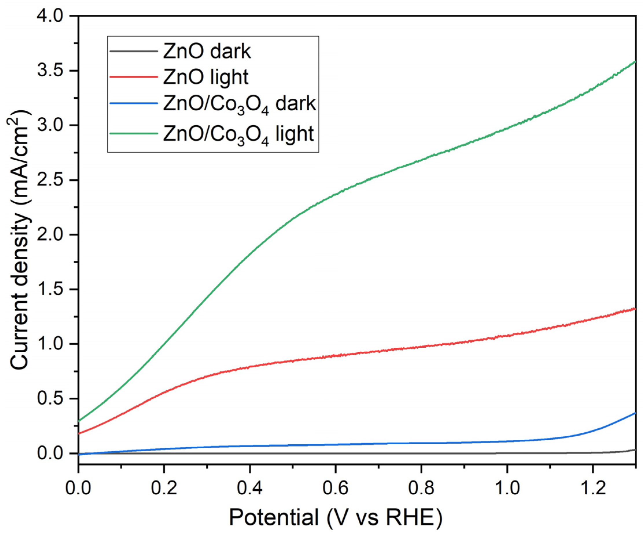
ZnO/Co3O40.5 M Na2S/Na2SO3Xe lamp 300 W3.46This work
ZnO/CoO0.03 M boraxXe lamp 300 W1.26[23]
ZnO/WO3−x1 M Na2SO4Xe arc lamp
300 W
2.39[55]
ZnO NSs-NRs@TiO2-Au0.5 M Na2SO4-1.73[56]
ZnO@TiO20.1 M NaOHXe lamp
450 W
0.40[57]
SnS2/b-ZnO0.25 M Na2S/
0.35 M Na2SO3
Xe arc lamp
300 W
0.58[58]
Y-ZnO0.1 M Na2SO4Xe arc lamp
500 W
0.50[59]
Disclaimer/Publisher’s Note: The statements, opinions and data contained in all publications are solely those of the individual author(s) and contributor(s) and not of MDPI and/or the editor(s). MDPI and/or the editor(s) disclaim responsibility for any injury to people or property resulting from any ideas, methods, instructions or products referred to in the content.

