
An Investigation into PVA Fiber Modified with SiO2 for Improving Mechanical Properties of Oil-Well Cements

Abstract
1. Introduction
2. Experimental
2.1. Materials
2.2. Modification of PVAFs
2.2.1. Preparation of PVAF Suspension
2.2.2. Preparation of Silica Layer Precursor
2.2.3. Preparation of Modified PVAFs
2.3. Preparation of the Mixed Cement
2.4. Characterization of PVAF Surface
2.5. Rheology Tests
2.6. Mechanical Properties of OWCs
2.7. Microstructure Tests of OWCs
2.8. XRD Test
2.9. Thermogravimetric Analysis
3. Results and Discussion
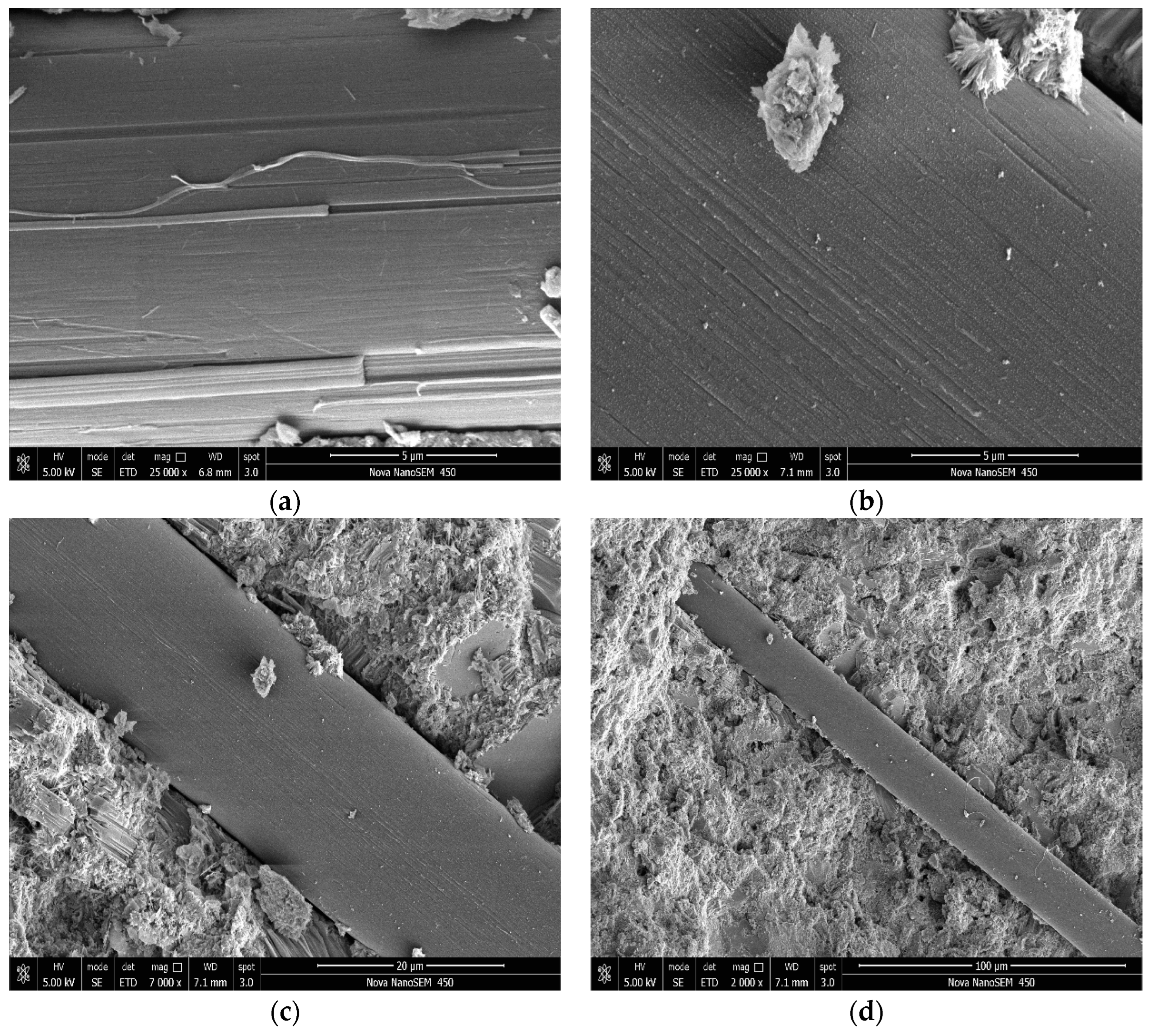
3.1. SEM Images for PVAFs
3.2. Rheology
3.3. Mechanical Properties
3.3.1. Compressive Strength
3.3.2. Flexural Strength
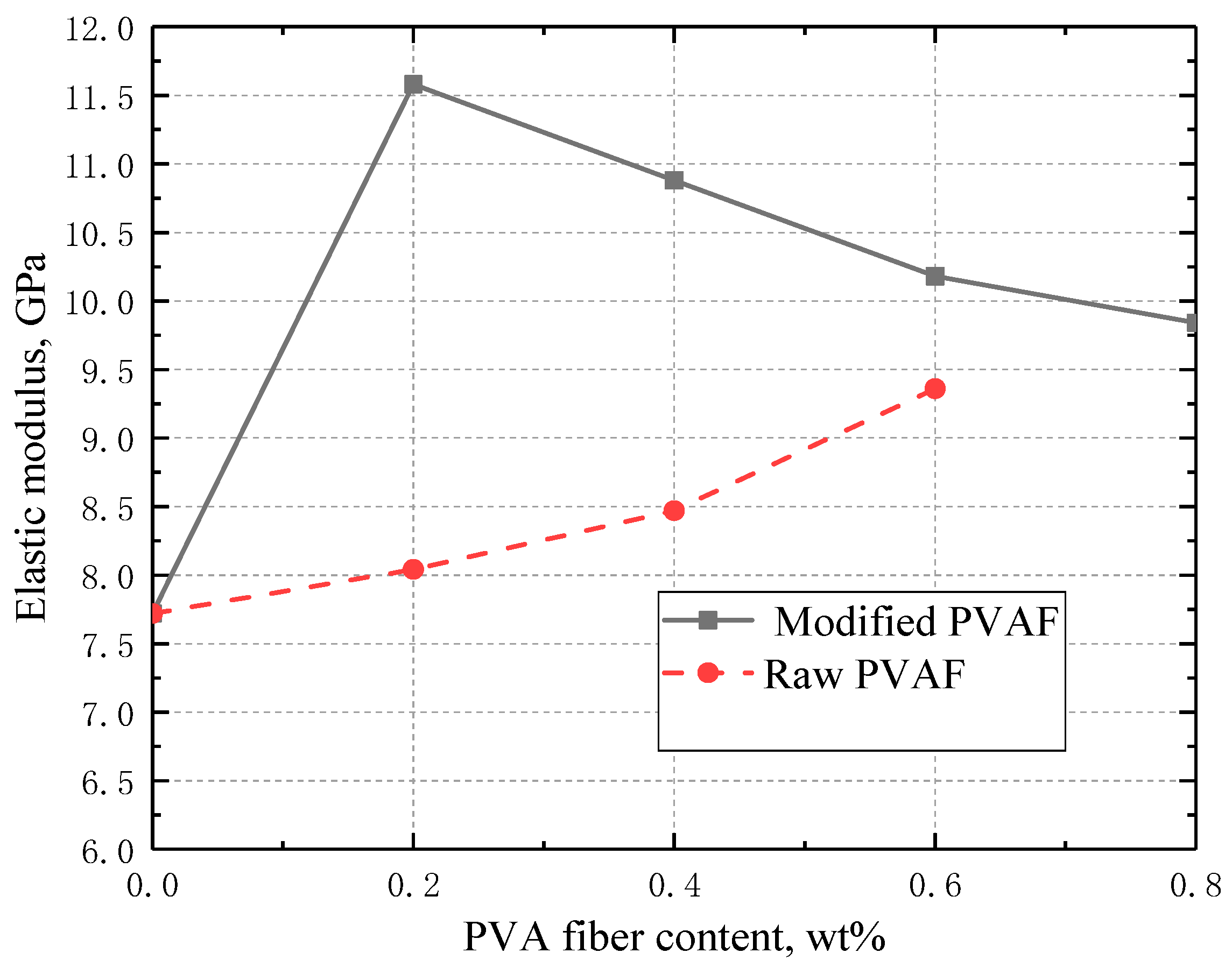
3.3.3. Elastic Modulus
3.4. SEM for OWC Micromorphology
4. Conclusions
- (1)
- The compressive strength of the cement stone incorporated with 0.2 wt% of the modified PVAFs was enhanced by 37.7% and 15.1% compared with those of cement stone without and with raw PVAFs, respectively. The flexural strength of the cement stone incorporated with 0.4 wt% of the modified PVAFs was enhanced by 66.1% and 27.1%, respectively, compared with those of cement stone without and with raw PVAFs.
- (2)
- Both compressive and flexural strength are first increased and then decreased with the PVAF content. The enhancing effect of modified PVAFs on elastic modulus is much larger than that of raw PVAF, while the elastic modulus is enhanced by 50.0% with the addition of 0.2 wt% modified PVAF.
- (3)
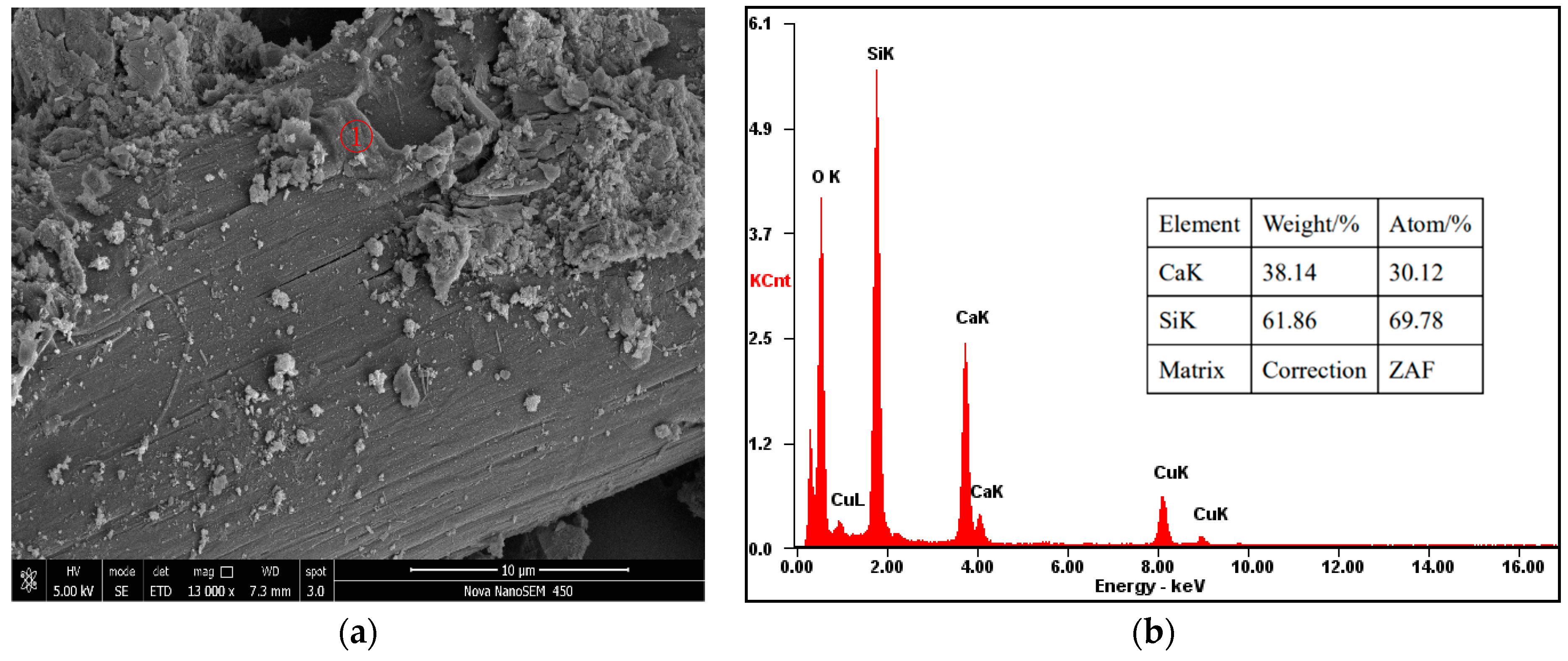
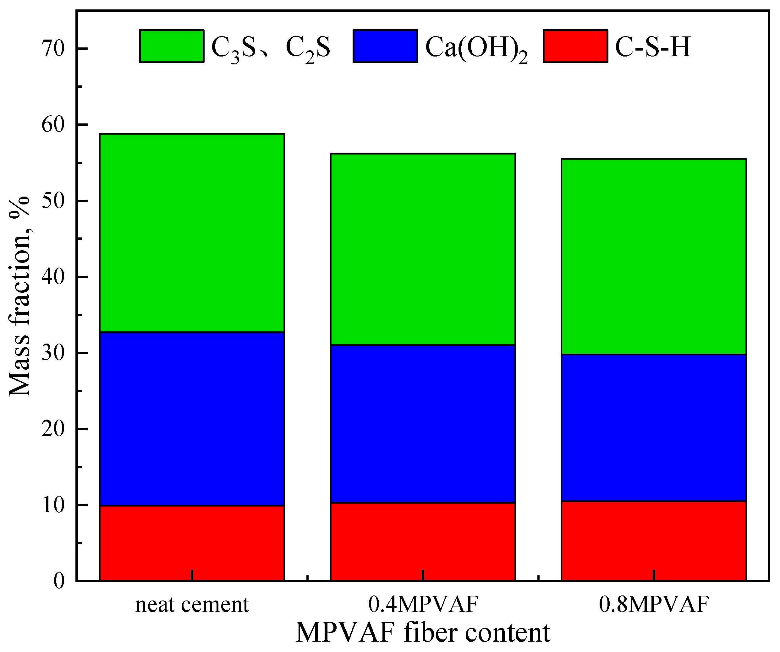
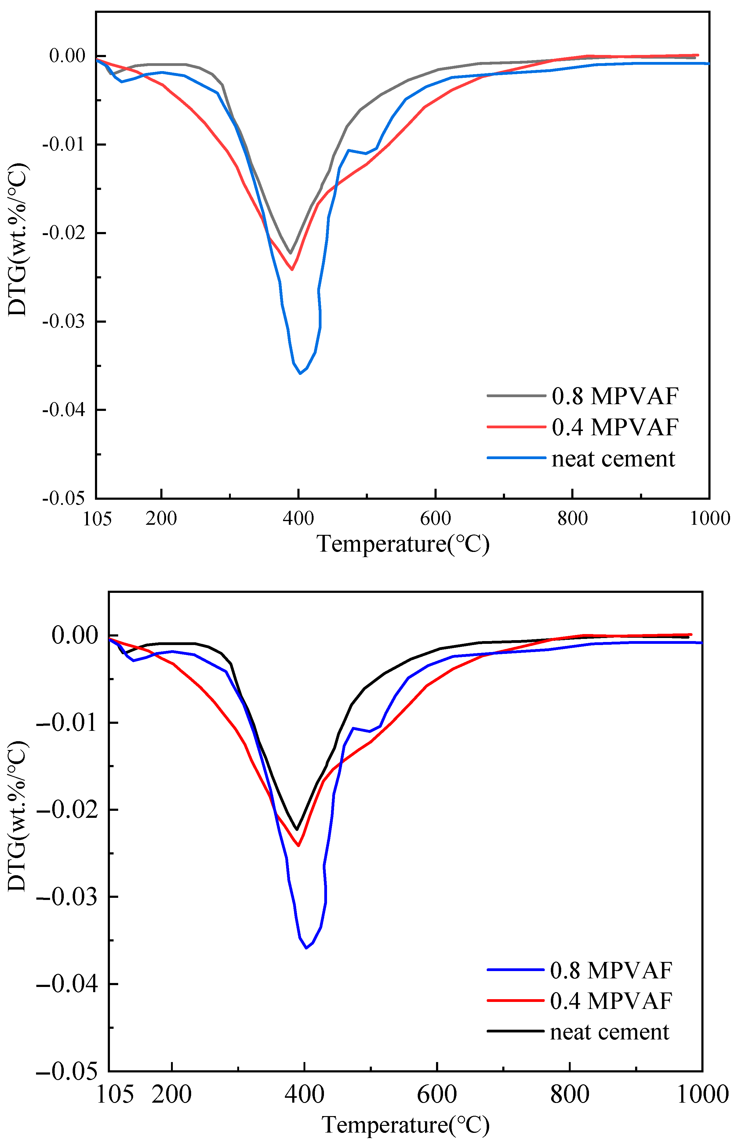
- The SEM test (EDX) test, XRD test, and thermogravimetric test prove that the SiO2 coating on the PVAF surface can promote the hydration of cement clinker, and can react with Ca(OH)2 to generate CSH gel. The SiO2 grafted onto the surface of PVAFs can improve the bond strength at the fiber/cement matrix interface, thus improving the mechanical properties of cement stone.
Author Contributions
Funding
Institutional Review Board Statement
Informed Consent Statement
Data Availability Statement
Conflicts of Interest
Nomenclature
| CBC | cement-based composite |
| MPVAF-OWC | modified PVAF reinforced oil-well cement |
| OWC | oil-well cement |
| PVA | polyvinyl alcohol |
| RPVAF-OWC | raw PVAF reinforced oil-well cement |
| SEM | scanning electron microscope |
| TEOS | tetraethyl orthosilicate |
References
- Salehi, S.; Khattak, M.J.; Ali, N.; Ezeakacha, C.; Saleh, F.K. Study and Use of Geopolymer Mixtures for Oil and Gas Well Cementing Applications. J. Energy Resour. Technol. 2017, 140, 012908. [Google Scholar] [CrossRef]
- Taleghani, D.A.; Li, G.; Moayeri, M. Smart Expandable Cement Additive to Achieve Better Wellbore Integrity. J. Energy Resour. Technol. 2017, 139, 062903. [Google Scholar] [CrossRef]
- Khalifeh, M.; Saasen, A.; Hodne, H.; Godøy, R.; Vrålstad, T. Geopolymers as an Alternative for Oil Well Cementing Applications: A Review of Advantages and Concerns. J. Energy Resour. Technol. 2018, 140, 092801. [Google Scholar] [CrossRef]
- Romanowski, N.; Ichim, A.; Teodoriu, C. Investigations on Oilwell Cement Strength Response to Ultrasonic Measurements in the Presence of Additives. J. Energy Resour. Technol. 2018, 140, 072904. [Google Scholar] [CrossRef]
- Patel, H.; Salehi, S. Development of an Advanced Finite Element Model and Parametric Study to Evaluate Cement Sheath Barrier. J. Energy Resour. Technol. 2019, 141, 092902. [Google Scholar] [CrossRef]
- Atahan, H.N.; Pekmezci, B.Y.; Tuncel, E.Y. Behavior of PVA Fiber-Reinforced Rementitious Composites Under Static and Impact Flexural Effects. J. Mater. Civ. Eng. 2013, 25, 1438–1445. [Google Scholar] [CrossRef]
- Sun, M.; Zhu, J.Q.; Sun, T.; Chen, Y.Z.; Li, X.P.; Yin, W.S.; Han, J.L. Multiple Effects of Nano-CaCO3 and Modified Polyvinyl Alcohol Fiber on Flexure–Tension-Resistant Performance of Engineered Cementitious Composites. Constr. Build. Mater. 2021, 303, 124426. [Google Scholar] [CrossRef]
- Niu, M.; Zhang, J.; Li, G.; Song, Z.; Wang, X. Mechanical Properties of Polyvinyl Alcohol Fiber-Reinforced Sulfoaluminate Cement Mortar Containing High-Volume of Fly Ash. J. Build. Eng. 2021, 35, 101988. [Google Scholar] [CrossRef]
- George, M.; Sathyan, D.; Mini, K.M. Investigations on Effect of Different Fibers on the Properties of Engineered Cementitious Composites. Mater. Today Proc. 2021, 42, 1417–1421. [Google Scholar] [CrossRef]
- Zhang, P.; Wang, K.; Wang, J.; Guo, J.; Hu, S.; Ling, Y.F. Mechanical Properties and Prediction of Fracture Parameters of Geopolymer/Alkali-activated Mortar Modified with PVA Fiber and Nano-SiO2. Ceram. Int. 2020, 46, 20027–20037. [Google Scholar] [CrossRef]
- Singh, N.B.; Rai, S. Effect of Polyvinyl Alcohol on the Hydration of Cement with Rice Husk Ash. Cem. Concr. Res. 2001, 31, 239–243. [Google Scholar] [CrossRef]
- Yao, X.; Shamsaei, E.; Chen, S.; Zhang, Q.H.; De Souza, F.B.; Sagoe-Crentsil, K.; Duan, W. Graphene Oxide-Coated Poly (vinyl alcohol) Fibers for Enhanced Fiber-Reinforced Cementitious Composites. Compos. Part B Eng. 2019, 174, 107010. [Google Scholar] [CrossRef]
- Chen, X.; Wang, C.; Xue, Y. A Novel Thermo-Thickening Viscosity Modifying Admixture to Improve Settlement Stability of Cement Slurry Under High Temperatures. Constr. Build. Mater. 2021, 295, 123606. [Google Scholar] [CrossRef]
- Noushini, A.; Samali, B.; Vessalas, K. Effect of Polyvinyl Alcohol (PVA) Fibre on Dynamic and Material Properties of Fibre Reinforced Concrete. Constr. Build. Mater. 2013, 49, 374–383. [Google Scholar] [CrossRef]
- Dehghanpour, H.; Subasi, S.; Guntepe, S.; Emiroglu, M.; Marasli, M. Investigation of Fracture Mechanics, Physical and Dynamic Properties of UHPCs Containing PVA, Glass and Steel Fibers. Constr. Build. Mater. 2022, 328, 127079. [Google Scholar] [CrossRef]
- Ling, Y.; Zhang, P.; Wang, J.; Chen, Y. Effect of PVA Fiber on Mechanical Properties of Cementitious Composite with and without Nano-SiO2. Constr. Build. Mater. 2019, 229, 117068. [Google Scholar] [CrossRef]
- Pang, X.; Qin, J.; Sun, L.; Zhang, G.; Wang, H. Long-term Strength Retrogression of Silica-Enriched Oil Well Cement: A Comprehensive Multi-Approach Analysis. Cem. Concr. Res. 2021, 144, 106424. [Google Scholar] [CrossRef]
- Maagi, M.T.; Lupyana, S.D.; Jun, G. Nanotechnology in the Petroleum Industry: Focus on the Use of Nanosilica in Oil-Well Cementing Applications—A Review. J. Pet. Sci. Eng. 2020, 193, 107397. [Google Scholar] [CrossRef]
- Kumar, S.; Bera, A.; Shah, S.N. Potential Applications of Nanomaterials in Oil and Gas Well Cementing: Current Status, Challenges and Prospects. J. Pet. Sci. Eng. 2022, 213, 110395. [Google Scholar] [CrossRef]


| Chemical Composition (wt%) | Mineral Composition (wt%) | ||||||||
|---|---|---|---|---|---|---|---|---|---|
| AI2O3 | CaO | Fe2O3 | MgO | SiO2 | SO3 | C2S | C3A | C3S | C4AF |
| 2.89 | 65.08 | 2.63 | 0.83 | 24.76 | 1.25 | 30.46 | 2.80 | 53.70 | 8.00 |
| Length (mm) | Diameter (μm) | Density (g/cm3) | Tensile Strength (MPa) | Elastic Modulus (GPa) |
|---|---|---|---|---|
| 6 | 17 | 1.3 | 1600 | 40 |
| Formula | Cement, g | PVAF | Deformer | Water, g | W/C Ratio |
|---|---|---|---|---|---|
| PC | 900 | 0 | 1.8 g (0.2 wt%) | 396 | 0.44 |
| OWC-0.2 | 1.8 g (0.2 wt%) | ||||
| OWC-0.4 | 3.6 g (0.4 wt%) | ||||
| OWC-0.6 | 5.4 g (0.6 wt%) | ||||
| OWC-0.8 | 7.2 g (0.8 wt%) |
| Sample No. | Reading at Different Rotational Speeds (r/min) | Rheology Parameters | |||||
|---|---|---|---|---|---|---|---|
| 300 | 200 | 100 | 6 | 3 | n | K | |
| PC | 120 | 82 | 73 | 27 | 21 | 0.4524 | 3.6487 |
| RPVAF-OWC-0.2 | 130 | 106 | 79 | 22 | 18 | 0.4534 | 3.9293 |
| RPVAF-OWC-0.4 | 93 a | 66 a | 49 a | 20 a | 13 a | N/A | N/A |
| RPVAF-OWC-0.6 | 50 a | 36 a | 31 a | 17 a | 13 a | N/A | N/A |
| MPVAF-OWC-0.2 | 125 | 102 | 75 | 21 | 16 | 0.4650 | 3.5145 |
| MPVAF-OWC-0.4 | 127 | 103 | 76 | 21 | 17 | 0.4674 | 3.5178 |
| MPVAF-OWC-0.6 | 129 | 106 | 76 | 22 | 17 | 0.4816 | 3.2694 |
Disclaimer/Publisher’s Note: The statements, opinions and data contained in all publications are solely those of the individual author(s) and contributor(s) and not of MDPI and/or the editor(s). MDPI and/or the editor(s) disclaim responsibility for any injury to people or property resulting from any ideas, methods, instructions or products referred to in the content. |
© 2024 by the authors. Licensee MDPI, Basel, Switzerland. This article is an open access article distributed under the terms and conditions of the Creative Commons Attribution (CC BY) license (https://creativecommons.org/licenses/by/4.0/).
Share and Cite
Wu, Z.; Chen, Z.; Liu, J.; Wang, C. An Investigation into PVA Fiber Modified with SiO2 for Improving Mechanical Properties of Oil-Well Cements. Materials 2024, 17, 2581. https://doi.org/10.3390/ma17112581
Wu Z, Chen Z, Liu J, Wang C. An Investigation into PVA Fiber Modified with SiO2 for Improving Mechanical Properties of Oil-Well Cements. Materials. 2024; 17(11):2581. https://doi.org/10.3390/ma17112581
Chicago/Turabian StyleWu, Zhiqiang, Zehua Chen, Jingping Liu, and Chengwen Wang. 2024. "An Investigation into PVA Fiber Modified with SiO2 for Improving Mechanical Properties of Oil-Well Cements" Materials 17, no. 11: 2581. https://doi.org/10.3390/ma17112581
APA StyleWu, Z., Chen, Z., Liu, J., & Wang, C. (2024). An Investigation into PVA Fiber Modified with SiO2 for Improving Mechanical Properties of Oil-Well Cements. Materials, 17(11), 2581. https://doi.org/10.3390/ma17112581