
A Novel Method for Preparing Lightweight and High-Strength Ceramisite Coarse Aggregates from Solid Waste Materials

Abstract
:1. Introduction
2. Experimental Procedure
2.1. Raw Materials
2.2. Methods
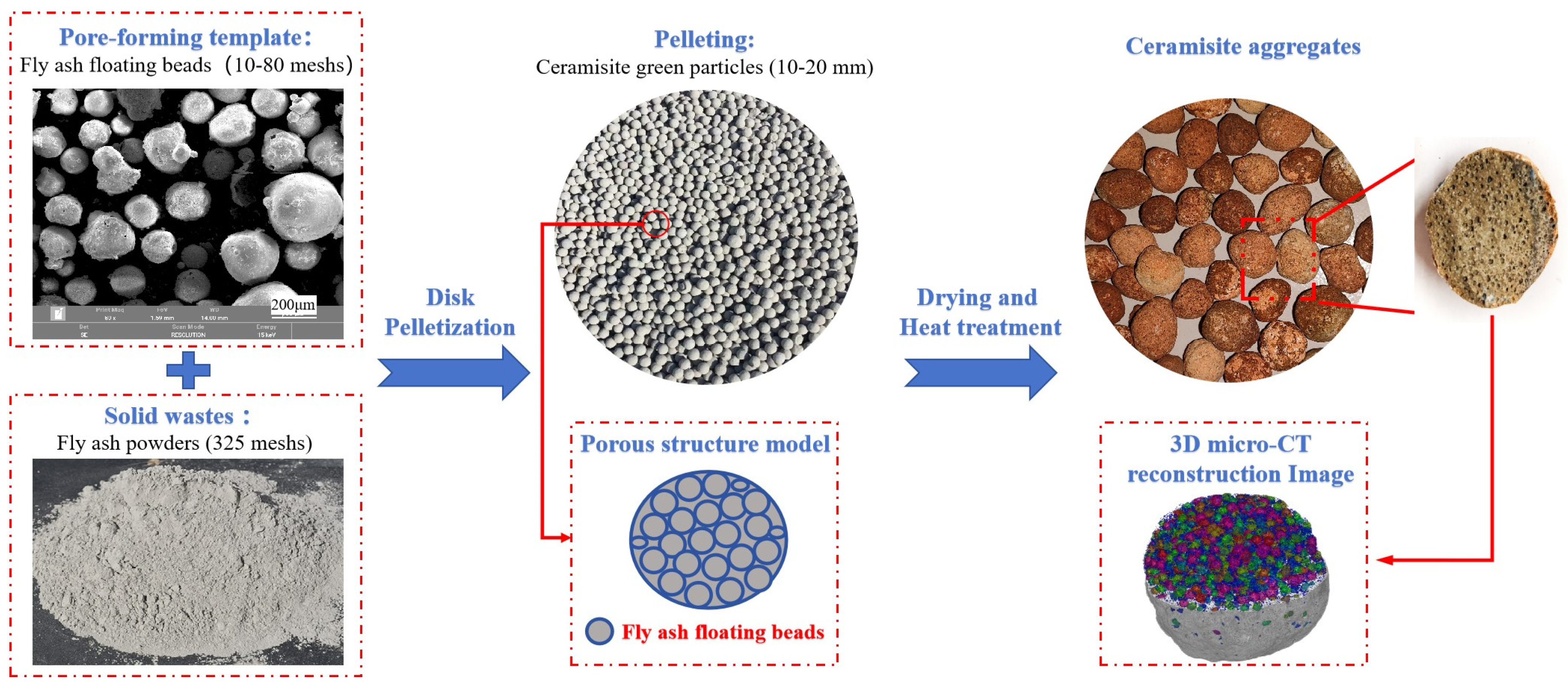
2.2.1. Preparation of Ceramisite
2.2.2. Testing and Characterization Methods
3. Results and Discussion
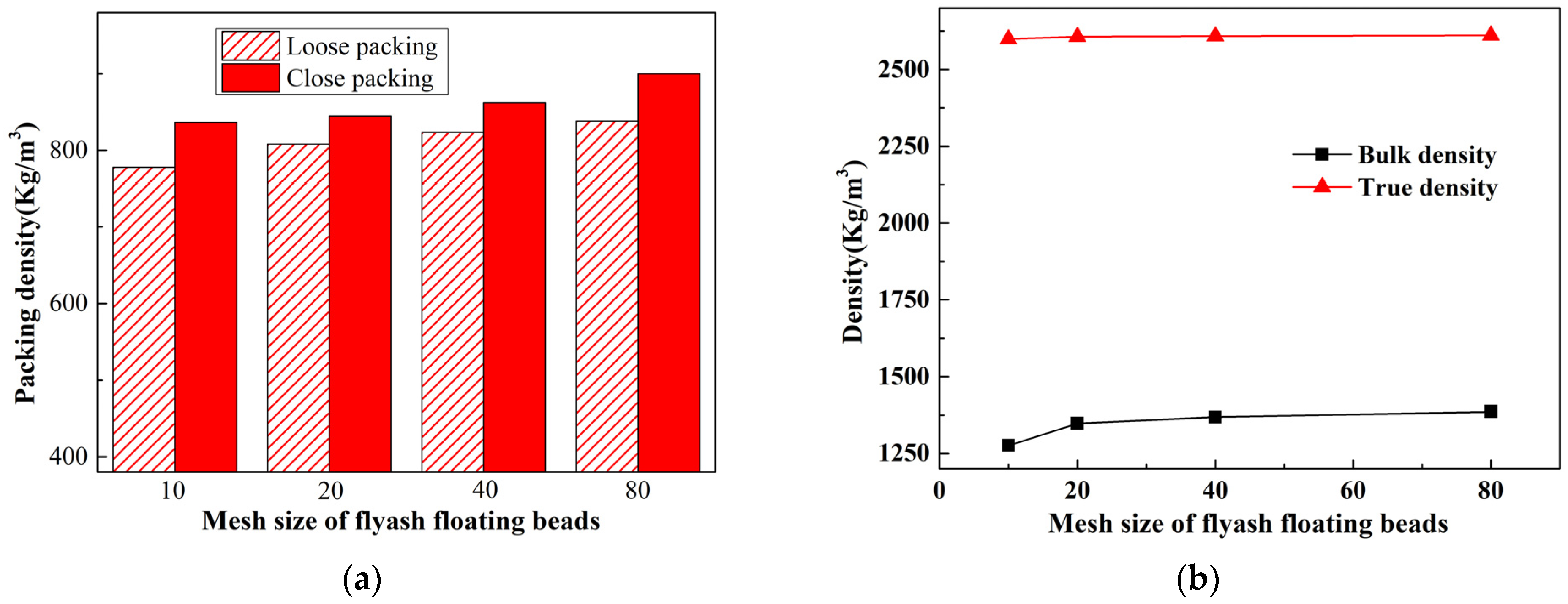
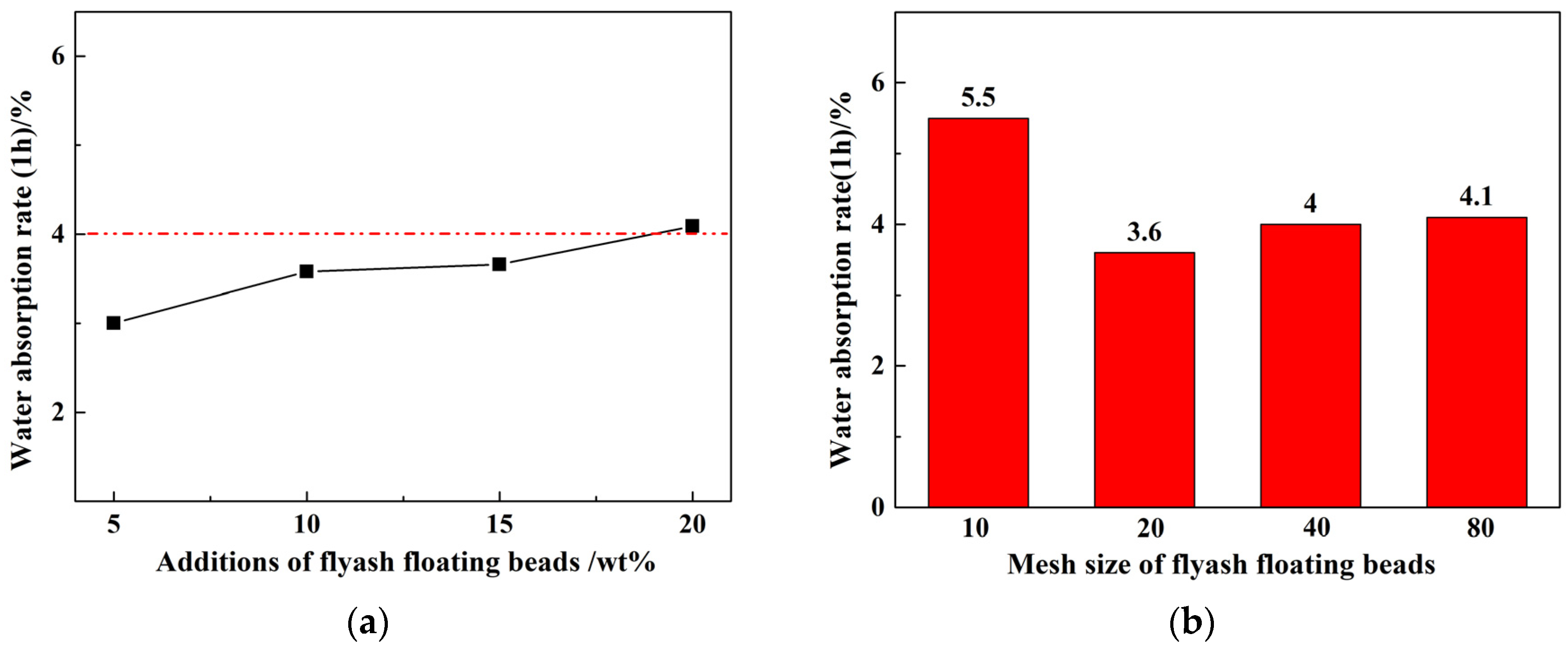
3.1. Physical Properties
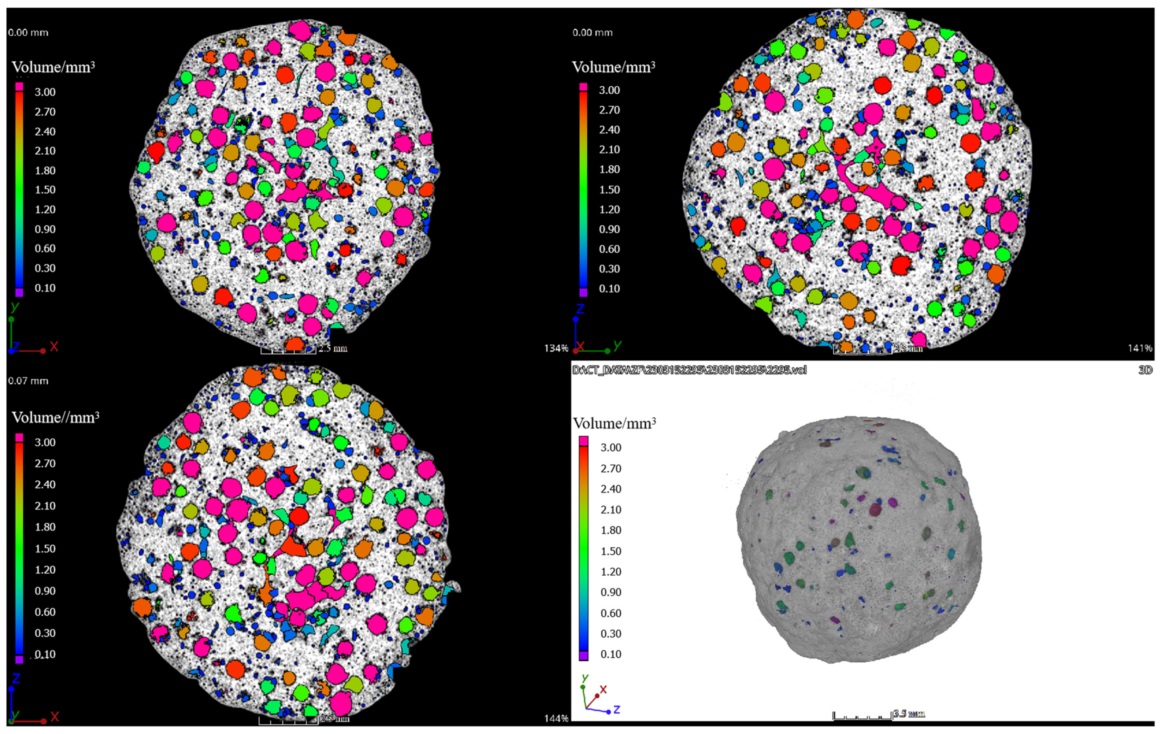
3.2. CT Analysis
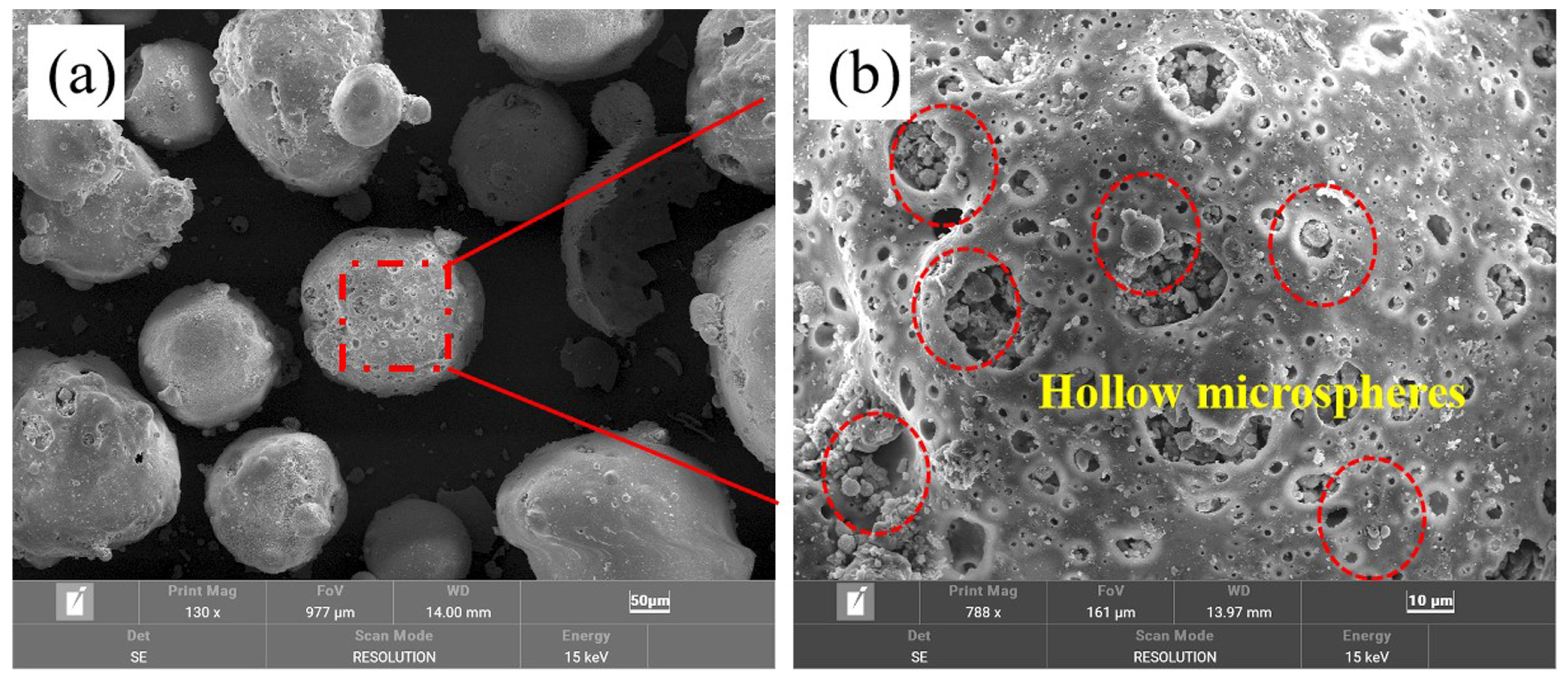
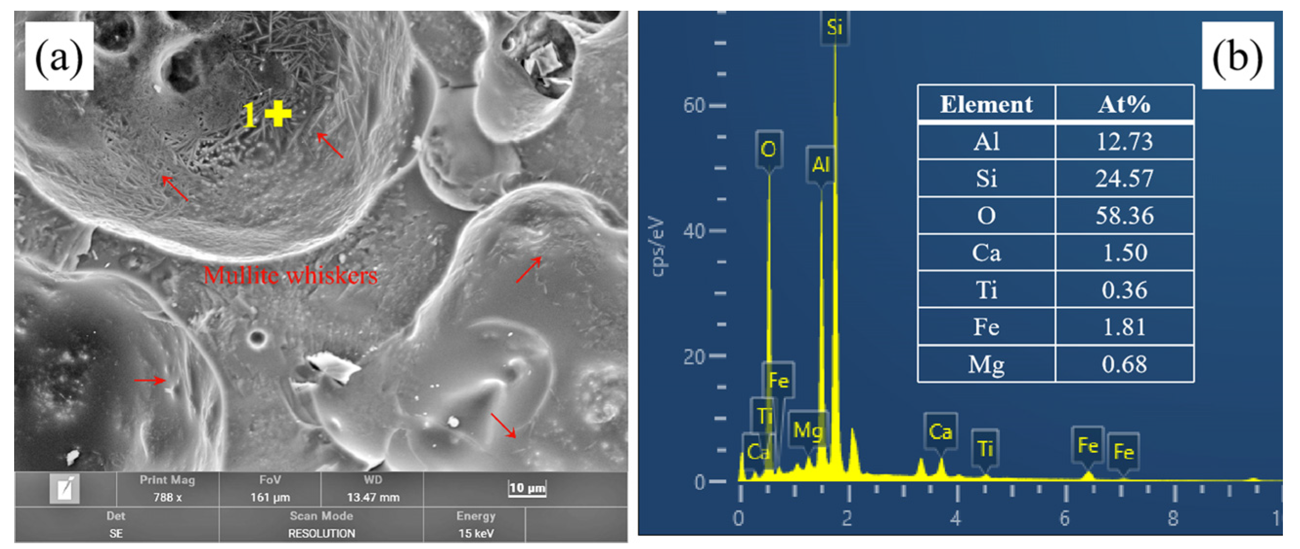
3.3. Microstructure
3.4. Phase Analysis
3.5. Analysis of the Adjustable and Controllable Structure of the Ceramisite Coarse Aggregates
3.6. Analysis of the Simultaneous Consideration of Light Weight and Strength
Characteristics of the Ceramisite Coarse Aggregates
3.7. Analysis of the Low Water Absorption Rate of Ceramisite Granules
4. Conclusions
- By using fly ash as the raw material and CAFBs as the pore-forming templates, ceramisite green bodies were prepared using a disc granulator. After high-temperature sintering, lightweight, high-strength, and low water absorption ceramisite coarse aggregates with excellent performance indicators were obtained, which far exceed the lightweight and high-strength requirements of the ceramisite coarse aggregates described in GB/T 17431.1-2010. With the addition of 40-mesh CAFBs at 10 wt%, high-quality ceramisite coarse aggregates with a packing density of 823 kg/m3, a cylinder compressive strength of 12.5 MPa, and a 1 h water absorption rate of 4.0% were successfully produced.
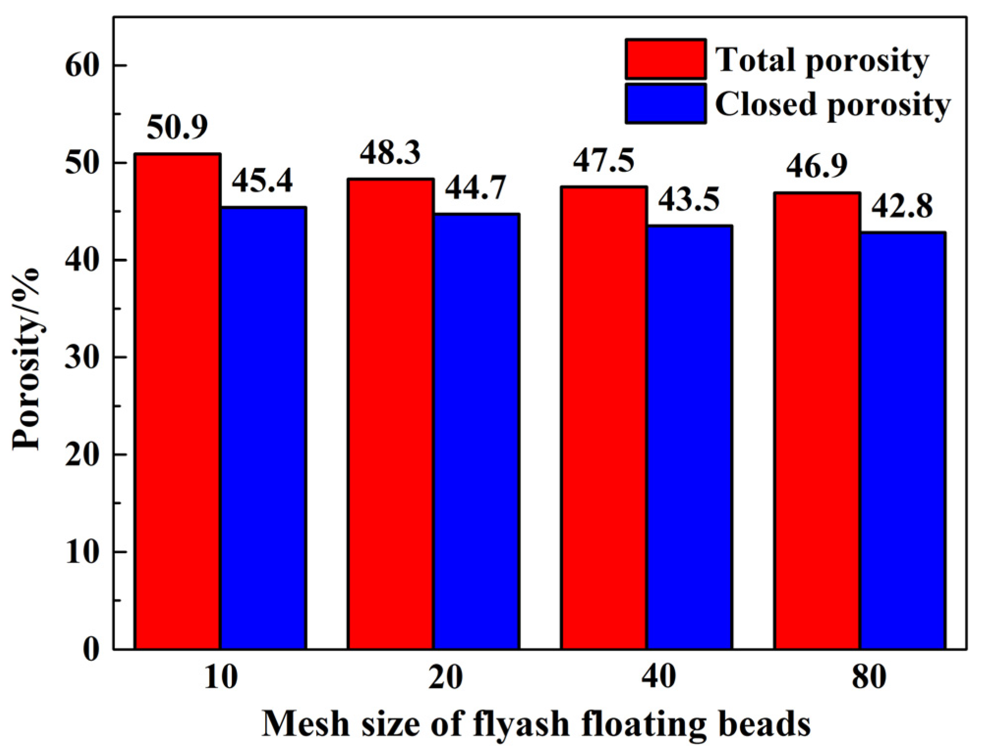
- The pore structure characteristics of the ceramisite coarse aggregates after firing could be tailored and regulated through the manipulation of floating bead size, quantity, and distribution.
- The resulting ceramisite coarse aggregates possessed a spherical isolated distribution of pores and a dense shell layer on the surface after the firing process. This structural arrangement provided a structural basis for the preparation of high-quality ceramisite coarse aggregates.
Author Contributions
Funding
Institutional Review Board Statement
Informed Consent Statement
Data Availability Statement
Conflicts of Interest
References
- Han, Y.; Wang, H.; Xu, Y.; Cao, Y.; Liu, R. Effect of additives on properties and microstructure of lightweight aggregates produced from mswi bottom ash sludge (mswi-bas). J. Air Waste Manag. Assoc. 2021, 8, 1013–1024. [Google Scholar] [CrossRef] [PubMed]
- Rehman, M.U.; Rashid, K.; Haq, E.U.; Hussain, M.; Shehzad, N. Physico-mechanical performance and durability of artificial lightweight aggregates synthesized by cementing and geopolymerization. Constr. Build. Mater. 2020, 232, 117290. [Google Scholar] [CrossRef]
- Tang, P.; Jiang, S.; Chen, W.; Deng, T. Self-foaming high strength Artificial lightweight aggregates derived from solid wastes: Expansion mechanism and environmental impact. Constr. Build. Mater. 2023, 370, 130698. [Google Scholar] [CrossRef]
- Nguyen, H.P.; Mueller, A.; Nguyen, V.T.; Nguyen, C.T. Development and characterization of lightweight aggregate recycled from construction and demolition waste mixed with other industrial by products. Constr. Build. Mater. 2021, 313, 125472. [Google Scholar] [CrossRef]
- Li, X.; He, C.; Lv, Y.; Jian, S.; Jiang, W.; Jiang, D.; Wu, K.; Dan, J. Effect of sintering temperature and dwelling time on the characteristics of lightweight aggregate produced from sewage sludge and waste glass powder. Ceram. Int. 2021, 47, 33435–33443. [Google Scholar] [CrossRef]
- Cao, Y.; Liu, R.; Xu, Y.; Ye, F.; Xu, R.; Han, Y. Effect of SiO2, Al2O3 and CaO on characteristics of lightweight aggregates produced from MSWI bottom ash sludge (MSWI-BAS). Constr. Build. Mater. 2019, 205, 368–376. [Google Scholar] [CrossRef]
- Liu, M.; Wang, C.; Bai, Y.; Xu, G. Effects of sintering temperature on the characteristics of lightweight aggregate made from sewage sludge and river sediment. J. Alloys Compd. 2018, 748, 522–527. [Google Scholar] [CrossRef]
- Li, X.; He, C.; Lv, Y.; Jian, S.; Liu, G.; Jiang, W.; Jiang, D. Utilization of municipal sewage sludge and waste glass powder in production of lightweight aggregates. Constr. Build. Mater. 2020, 256, 119413. [Google Scholar] [CrossRef]
- Gonzalez-Corrochano, B.; Alonso-Azcarate, J.; Rodriguez, L.; Perez Lorenzo, A.; Fernandez Torio, M.; Tejado Ramos, J.J. Valorization of washing aggregate sludge and sewage sludge for lightweight aggregates production. Constr. Build. Mater. 2016, 116, 252–262. [Google Scholar] [CrossRef]
- Liu, W.; Hu, Z.; Liu, C.; Huang, X.; Hou, J. Mechanical properties under triaxial compression of coal gangue-fly ash cemented backfill after cured at different temperatures. Constr. Build. Mater. 2024, 411, 134268. [Google Scholar] [CrossRef]
- Al-Shawabkeh, A. Fly Ash Utilization for Thermal Insulation Bricks Manufacturing. J. Solid Waste Technol. Manag. 2001, 27, 57–61. [Google Scholar]
- Saygılı, A.; Baykal, G. A new method for improving the thermal insulation properties of fly ash. Energy Build. 2011, 43, 3236–3243. [Google Scholar] [CrossRef]
- GB/17431.2-2010; Lightweight Aggregate and Its Test Methods Part 2: Test Methods for Lightweight Aggregates. China Standards Press: Beijing, China, 2010. (In Chinese)
- GB/17431.1-2010; Lightweight Aggregate and Its Test Methods Part 1: Lightweight Aggregate. China Standards Press: Beijing, China, 2010. (In Chinese)
- Wang, C.; Huang, C.; Xu, H.; Yuan, N.; Liu, X.; Bai, L. Ceramsite production using water treatment residue as main ingredient: The key affecting factors identification. J. Environ. Manag. 2022, 308, 114611. [Google Scholar] [CrossRef] [PubMed]
- Li, X.; Wang, P.; Qin, J.; Liu, Y.; Zhang, Y. Mechanical properties of sintered ceramsite from iron ore tailings affected by two-region structure. Constr. Build. Mater. 2020, 240, 117919. [Google Scholar] [CrossRef]
- Pei, J.; Pan, X.; Qi, Y.; Yu, H.; Tu, G. Preparation and characterization of ultra-lightweight ceramsite using non-expanded clay and waste sawdust. Constr. Build. Mater. 2022, 346, 128410. [Google Scholar] [CrossRef]
- Jiang, J.; Chen, S.; Jin, C.; Wang, G.; Liu, T.; Xu, T. Preparation and properties of high-strength lightweight aggregate ceramsite from nepheline tailings. Constr. Build. Mater. 2023, 368, 130458. [Google Scholar] [CrossRef]
- Li, X.; Zeng, H.; Sun, N.; Sun, W.; Tang, H.; Wang, L. Preparation of lightweight ceramsite by stone coal leaching slag, feldspar, and pore-forming reagents. Constr. Build. Mater. 2023, 370, 130642. [Google Scholar] [CrossRef]
- Long, Y.; Pu, K.; Yang, Y.; Huang, H.; Fang, H.; Shen, D.; Geng, H.; Ruan, J.; Gu, F. Preparation of High-strength ceramsite from municipal solid waste incineration fly ash and clay based on CaO-SiO2-Al2O3 system. Constr. Build. Mater. 2023, 368, 130492. [Google Scholar] [CrossRef]


| Raw Materials | Specification Parameters |
|---|---|
| Fly ash | 325 mesh |
| Coal ash floating beads (CAFBs) | 10, 20, 40, 80 mesh |
| Molasses | Solid content of 48 wt% |
| Raw Materials | wt% | |||||||||
|---|---|---|---|---|---|---|---|---|---|---|
| SiO2 | Al2O3 | Fe2O3 | CaO | K2O | TiO2 | MgO | Na2O | P2O5 | Loss | |
| Fly ash | 52.26 | 30.18 | 6.60 | 3.69 | 2.76 | 1.31 | 0.80 | 0.70 | 0.33 | 1.36 |
| Coal ash floating beads (CAFBs) | 59.02 | 26.43 | 5.55 | 1.53 | 2.83 | 0.98 | 1.30 | 1.73 | 0.20 | 0.43 |
| Sample Number | Fly Ash (wt%) | CAFB (wt%) | |||
|---|---|---|---|---|---|
| 10 Mesh | 20 Mesh | 40 Mesh | 80 Mesh | ||
| R5 | 95 | 5 | |||
| R10-10 | 90 | 10 | |||
| R10-20 | 90 | 10 | |||
| R10-40 | 90 | 10 | |||
| R10-80 | 90 | 10 | |||
| R15 | 85 | 15 | |||
| R20 | 80 | 20 | |||
| Process Type | Physical Properties of Ceramisite | Reference | ||||||
|---|---|---|---|---|---|---|---|---|
| Loose Packing Density /(kg·m−3) | Bulk Density /(g·cm−3) | 1 h Water Absorption Rate/% | 24 h Water Absorption Rate/% | CCS /MPa | Porosity /% | Particle Size/mm | ||
| High Melting Point Hollow Sphere Pore-Forming Template Process | 778–838 | 1.275–1.385 | 4.10–5.50 | -- | 6.3–11.8 | 46.9–50.9 | 10–20 | This work |
| 723–855 | 1.202–1.416 | 3.00–4.09 | -- | 8.7–13.5 | 45.9–52.2 | 10–20 | ||
| 500–600 | -- | ≤10 | -- | 4.0 | -- | 10–20 | GB/T17431.1-2010 [14] | |
| 600–700 | -- | ≤10 | -- | 5.0 | -- | 10–20 | ||
| 700–800 | -- | ≤10 | -- | 6.0 | -- | 10–20 | ||
| 800–900 | -- | ≤10 | -- | 6.5 | -- | 10–20 | ||
| Sintering Process | 386–507 | -- | -- | -- | 1.11–6.30 | 46.0–67.5 | 5–15 | Wang et al. (2022) [15] |
| 630–730 | 1.24–1.48 | -- | 23.54–38.36 | 1.23–3.01 | 8–10 | Beatriz González-Corrochano et al. (2016) [9] | ||
| High-Temperature Foaming Method | 570–820 | -- | 1.01–1.65 | -- | 6.75–11.51 | -- | 10 | Tang et al. (2023) [3] |
| 550–990 | -- | 10–16 | -- | 1–8 | -- | 6–10 | Hung Phong Nguyen. (2021) [4] | |
| About 580–1023 | -- | 5–42 | -- | 1.52–8.24 | -- | -- | Han et al.(2021) [1] | |
| 780 | -- | 1.01 | -- | 7.1 | 54.91 | 15 ± 1 | Li et al. (2021) [5] | |
| -- | 0.755–1.268 | 50–14 | -- | 0.5–6.18 | -- | 10–15 | Cao et al. (2019) [6] | |
| -- | 0.862–1.300 | 36–4 | -- | 2.02–8.82 | -- | 10–15 | Cao et al. (2019) [6] | |
| 836 | 1.672 | <12 | -- | 13.7 | -- | 5–8 | Liu et al. (2018) [7] | |
| 746.6–982.4 | 1.527–1.814 | 6.7–16.53 | -- | 4.25–10.53 | -- | 5–8 | Li et al. (2020) [16] | |
| 280 | -- | 12.5 | -- | 1.0 | -- | 12 | Pei et al. (2022) [17] | |
| 410–995 | 0.775–1.569 | 0.3–3.5 | -- | 1.8–12.4 | -- | 12 | Jiang et al. (2023) [18] | |
| 640–1071 | About 1.0–1.75 | 2.4–13.5 | -- | 3.3–9.0 | -- | 8–10 | Li et al. (2023) [19] | |
| 810 | 1.19 | 3.5 | -- | 11.2 | -- | -- | Long et al. (2023) [20] | |
Disclaimer/Publisher’s Note: The statements, opinions and data contained in all publications are solely those of the individual author(s) and contributor(s) and not of MDPI and/or the editor(s). MDPI and/or the editor(s) disclaim responsibility for any injury to people or property resulting from any ideas, methods, instructions or products referred to in the content. |
© 2024 by the authors. Licensee MDPI, Basel, Switzerland. This article is an open access article distributed under the terms and conditions of the Creative Commons Attribution (CC BY) license (https://creativecommons.org/licenses/by/4.0/).
Share and Cite
Xiong, X.; Wu, Z.; Jiang, P.; Lai, M.; Cheng, G. A Novel Method for Preparing Lightweight and High-Strength Ceramisite Coarse Aggregates from Solid Waste Materials. Materials 2024, 17, 2613. https://doi.org/10.3390/ma17112613
Xiong X, Wu Z, Jiang P, Lai M, Cheng G. A Novel Method for Preparing Lightweight and High-Strength Ceramisite Coarse Aggregates from Solid Waste Materials. Materials. 2024; 17(11):2613. https://doi.org/10.3390/ma17112613
Chicago/Turabian StyleXiong, Xin, Zhi Wu, Pengcheng Jiang, Min Lai, and Guanghai Cheng. 2024. "A Novel Method for Preparing Lightweight and High-Strength Ceramisite Coarse Aggregates from Solid Waste Materials" Materials 17, no. 11: 2613. https://doi.org/10.3390/ma17112613