

Weld Zone Analysis Based on FCAW Mechanical Characteristics and Heat Transfer Analysis of 316L Stainless Steel for Liquefied Hydrogen Tanks


Abstract
1. Introduction
2. Experimental Conditions
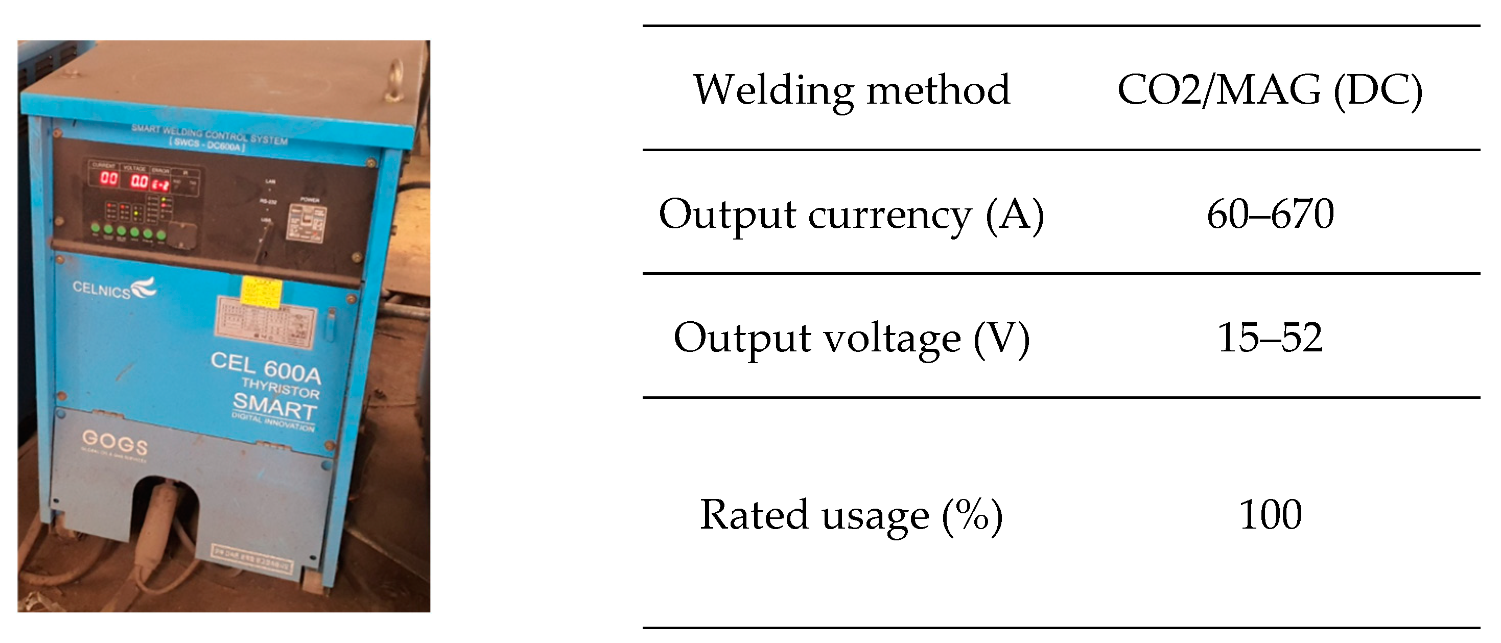
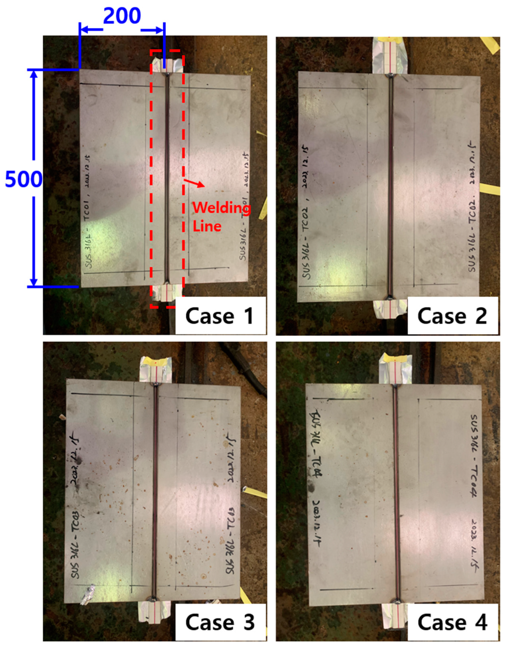
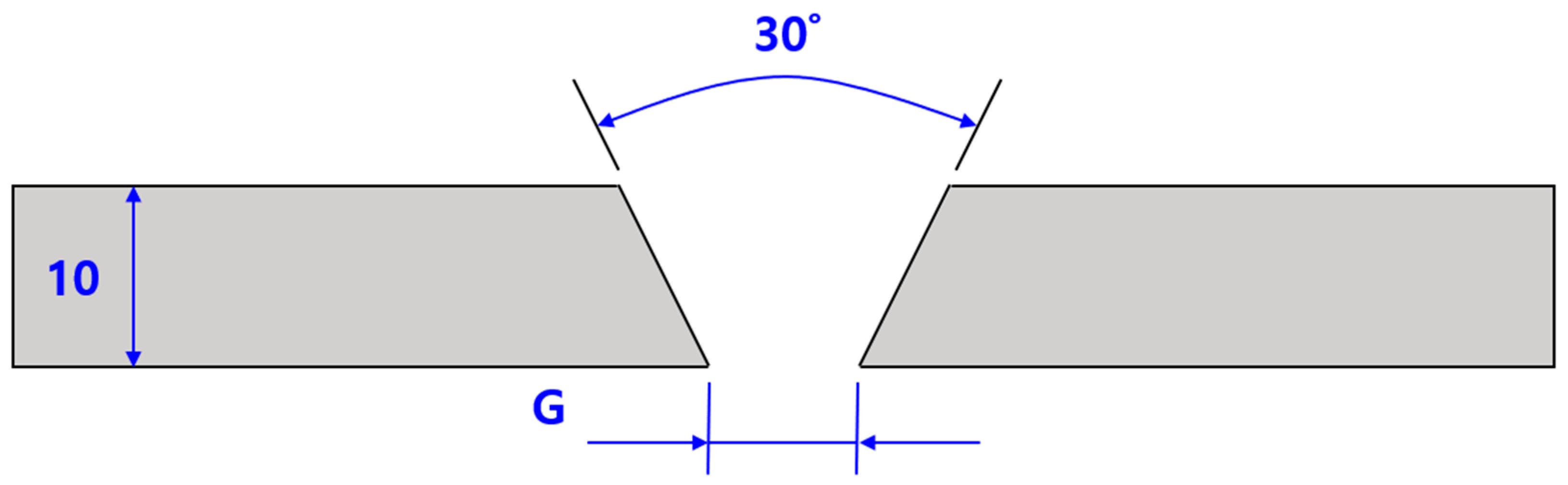
2.1. Welding Materials, Equipment, and Conditions
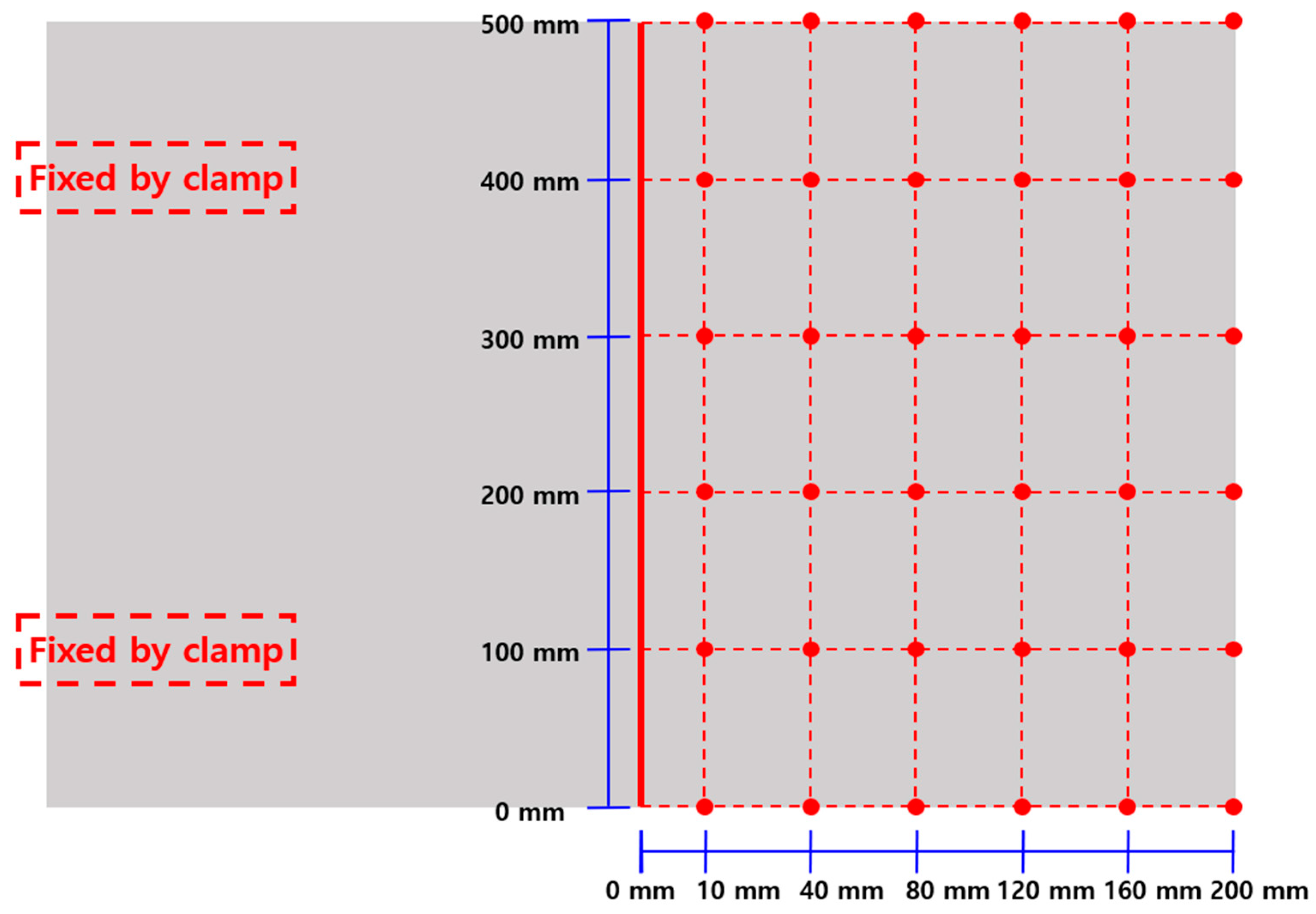
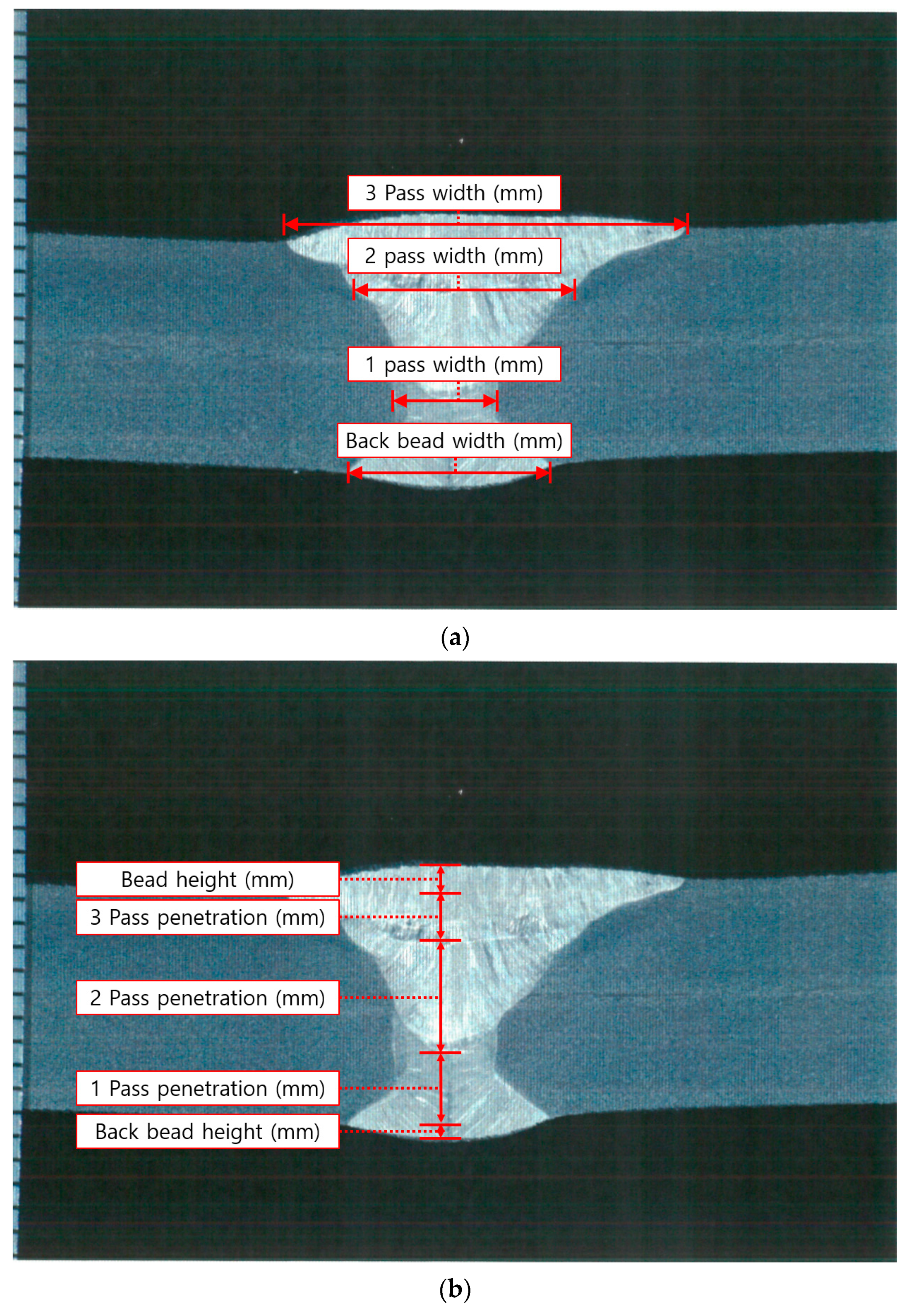
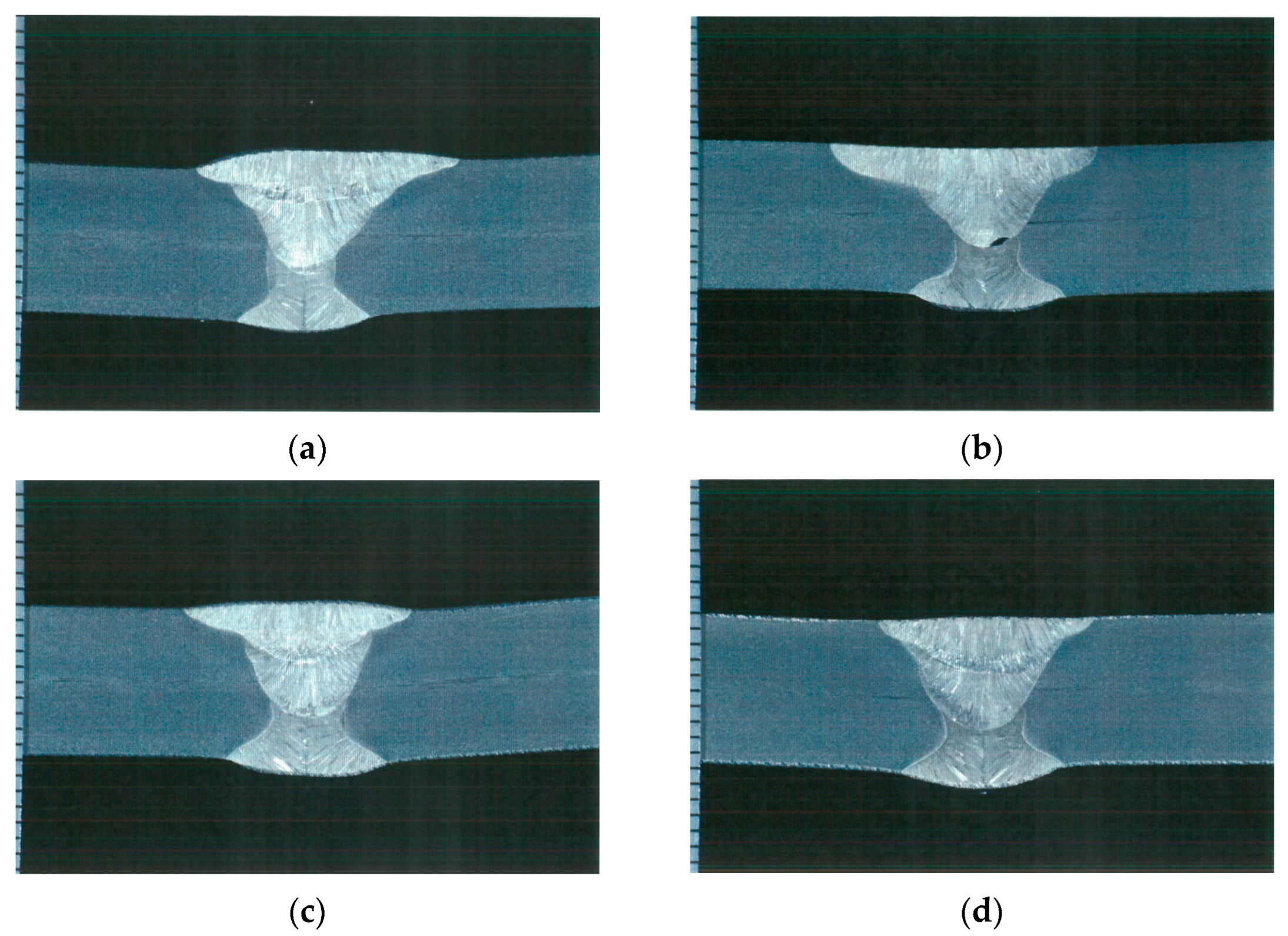
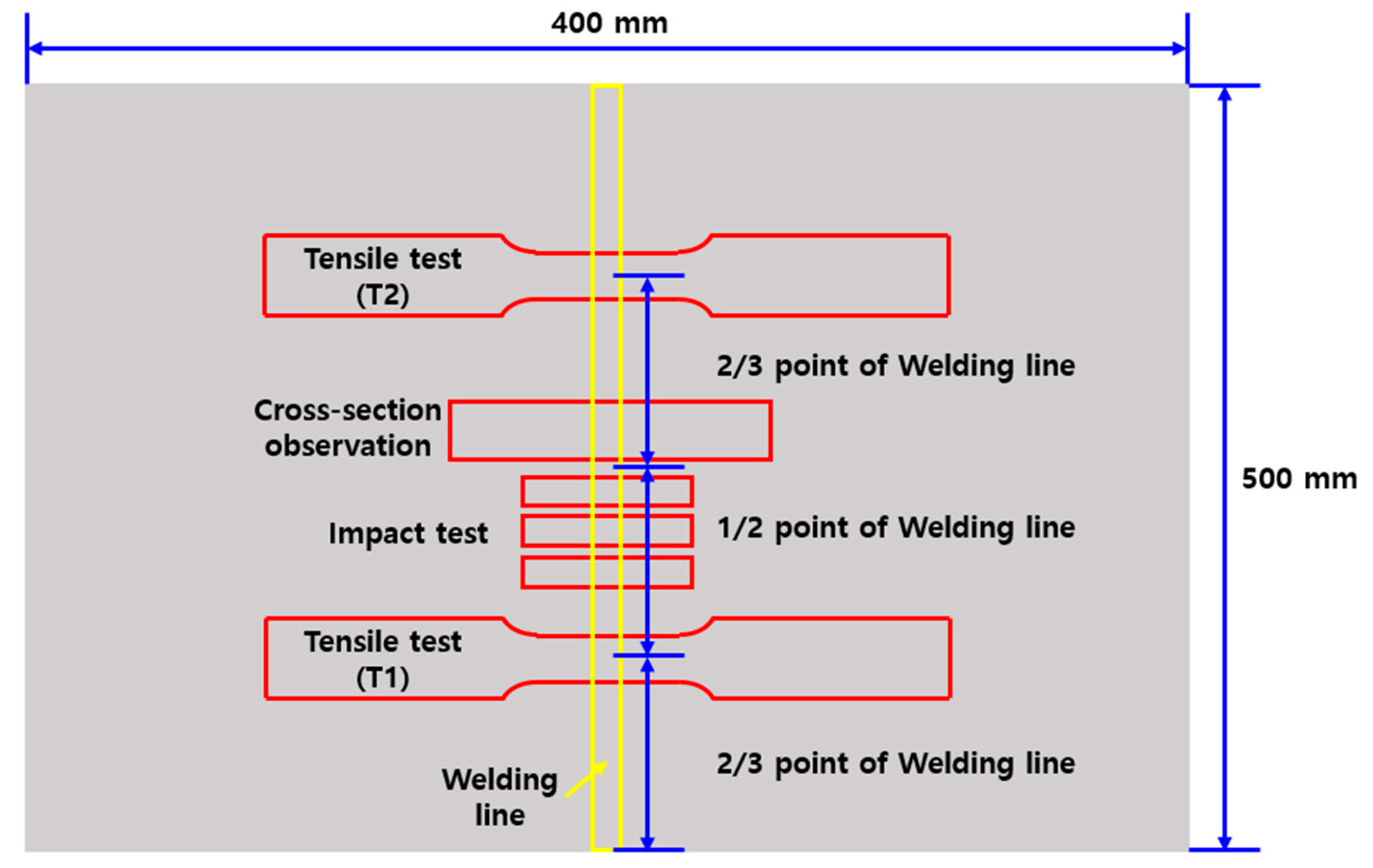
2.2. Microstructural Examination (Deformation Analysis, Cross-Section Observation)
3. Prediction of Welding Deformation Using FEM
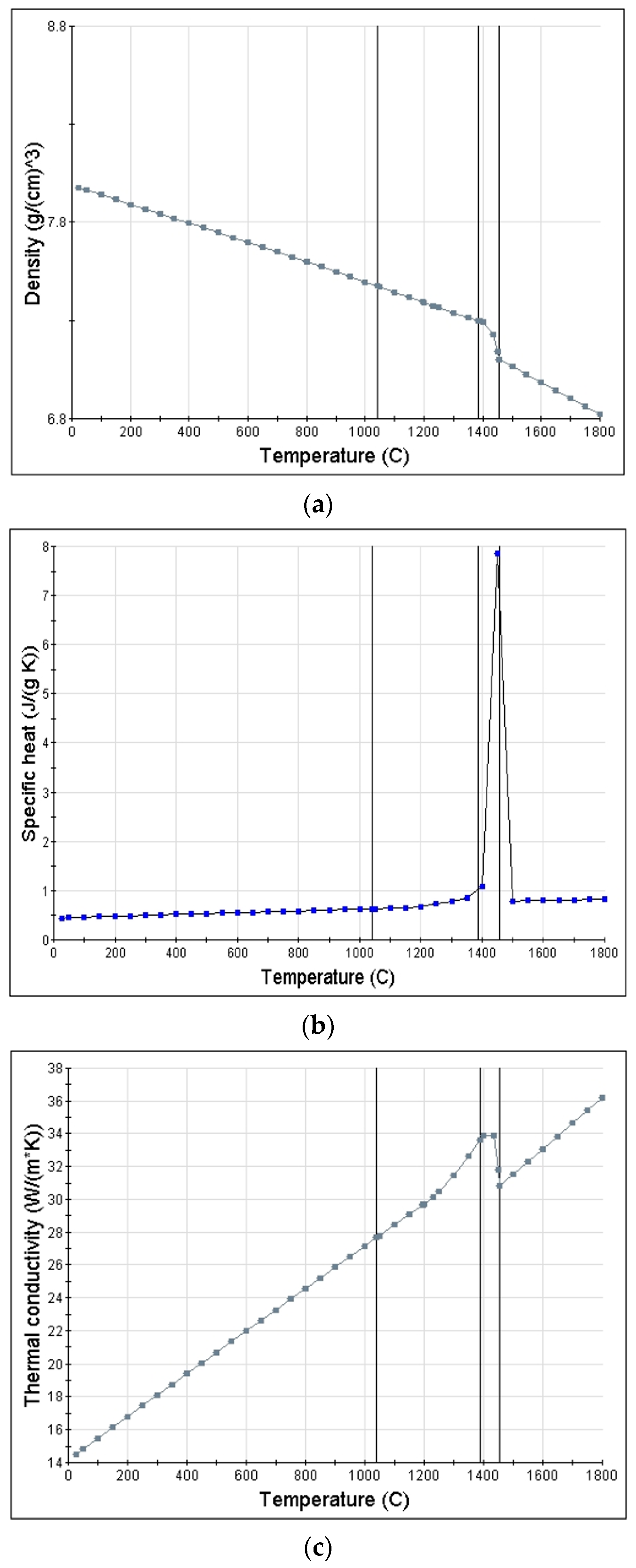
3.1. Heat Transfer Analysis
- Λ = λ(T): Thermal conductivity (W/mK).
- ∂U/∂t: The material time rate of internal energy (the specific heat, Cp(T), being given by ∂U/∂T, assuming the volume is held constant).
- Q: Volumetric source power (W/m3) with laser beam and electric arc volumetric heat sources taken into account.
- δT: Variational function.
- qS: Heat flux toward element surface.
- T = T(xα,t): Temperature (K).
- ρ: Density.
- Qh: Heat input amount applied per block volume.
- A: Current (A).
- V: Voltage (V).
- Ws: Welding speed (mm/min).
- A0: Cross-sectional area by welding pass (mm2).
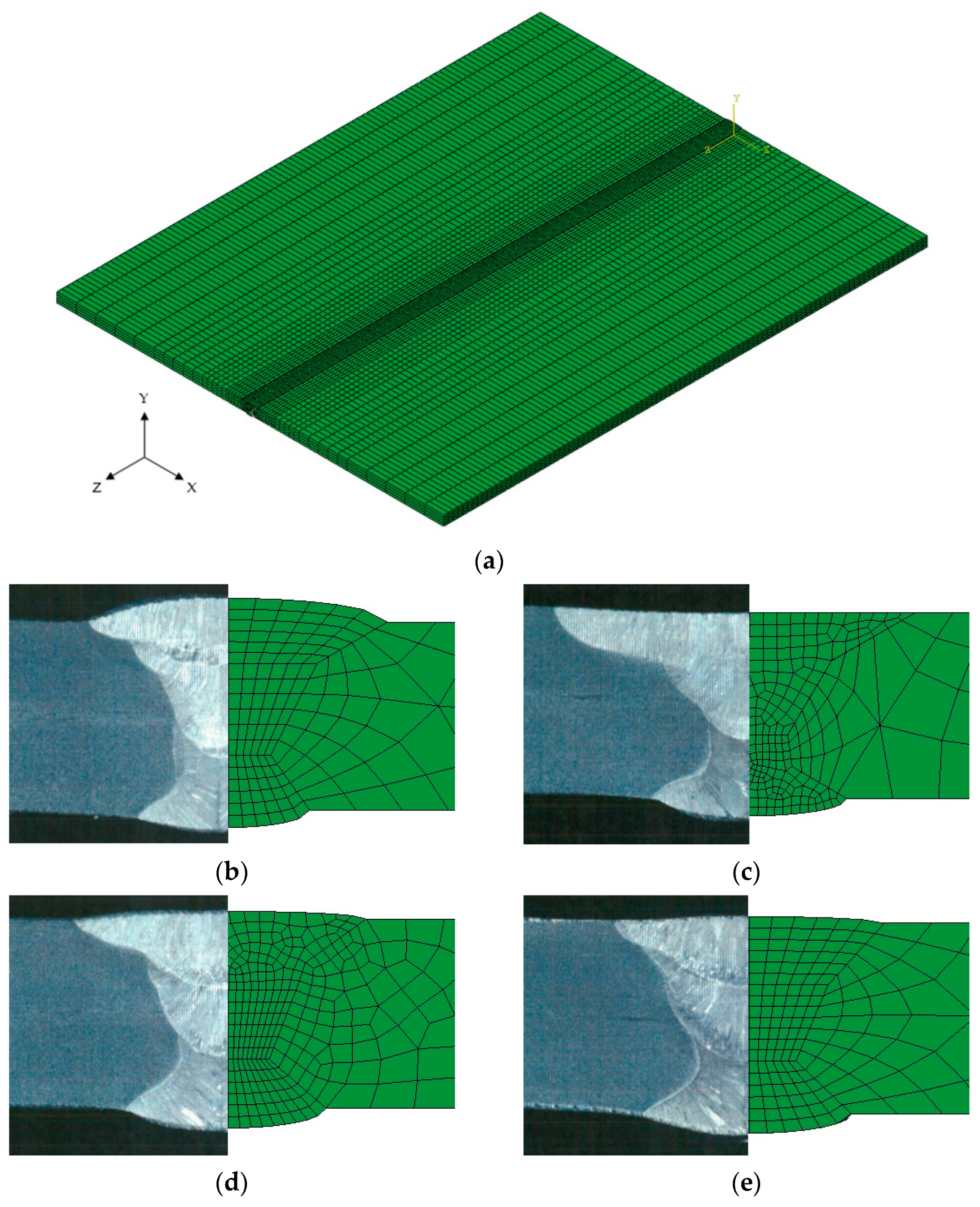
3.2. Construction of FEM Model
4. Results and Discussion
4.1. Results of Tensile, Impact, and Welding Deformation Measurement
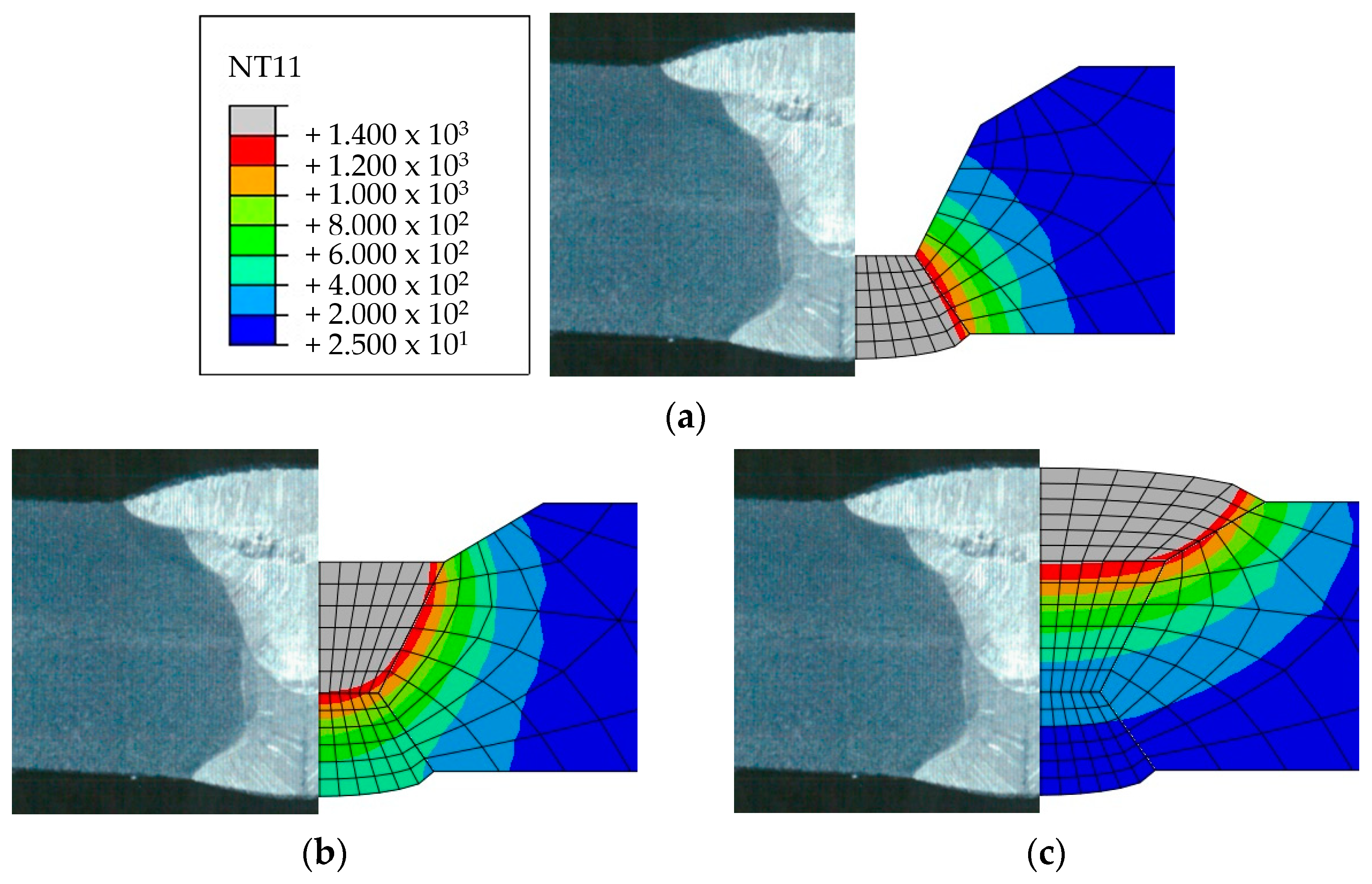
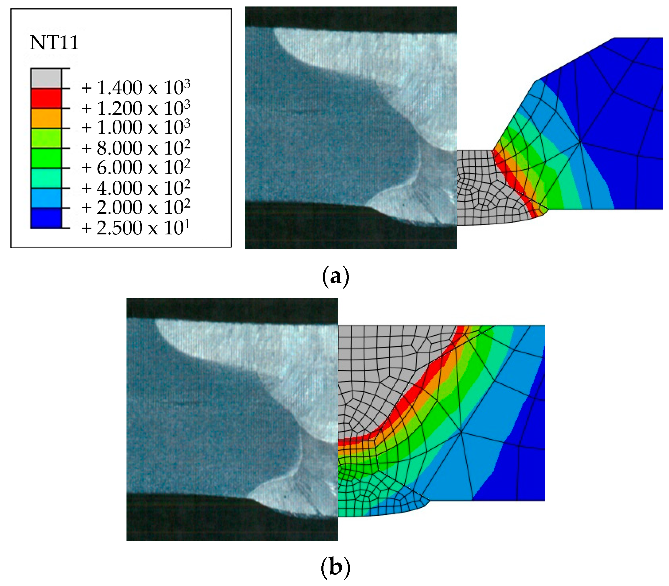
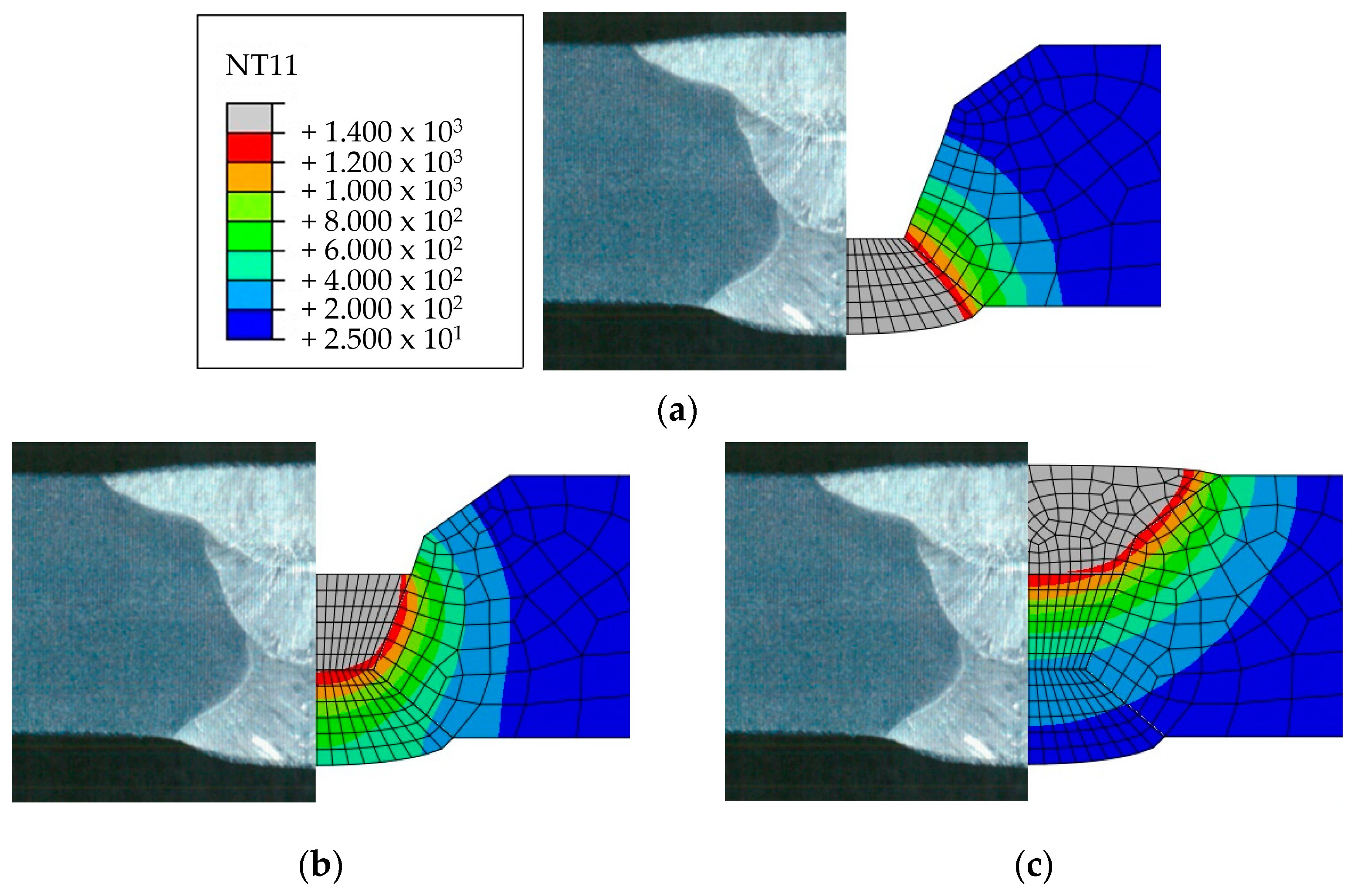
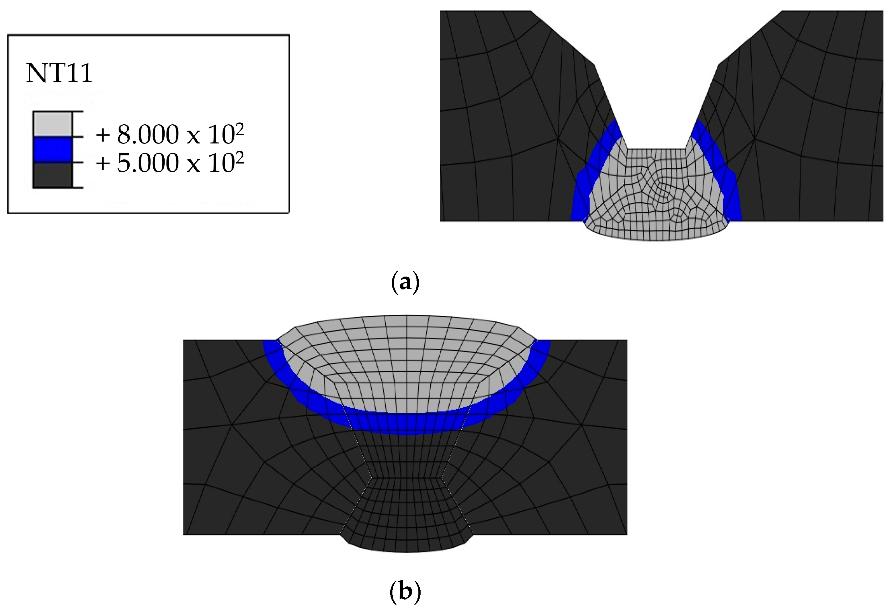
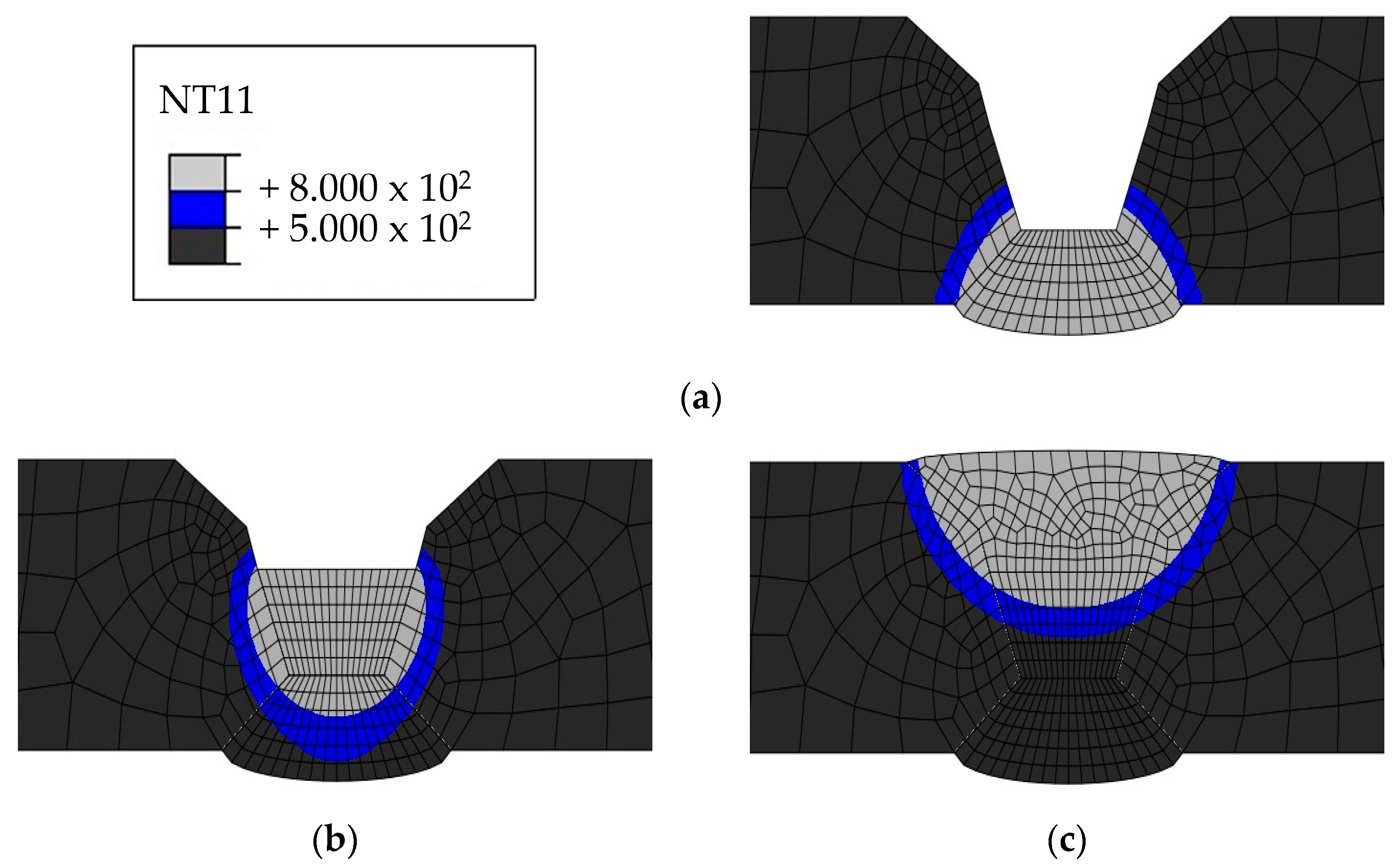
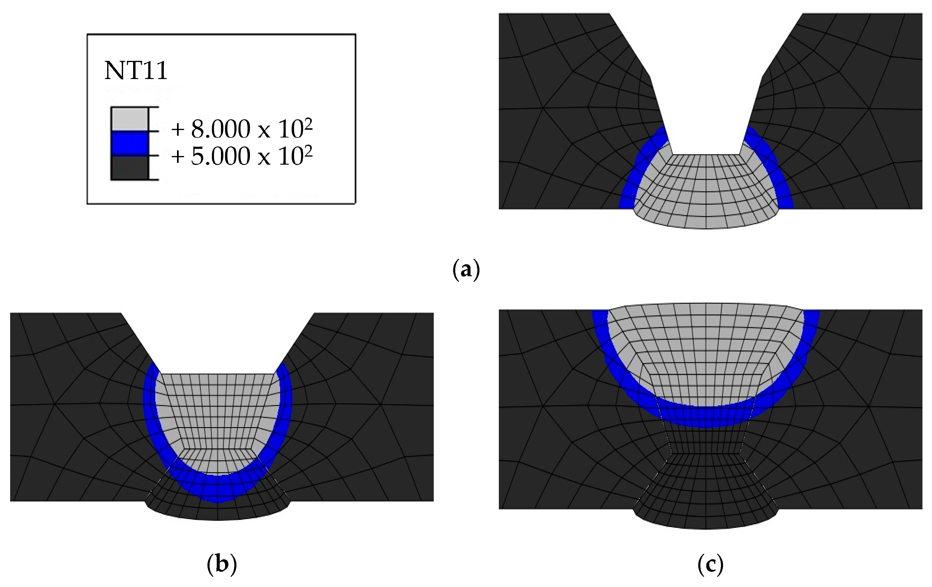
4.2. Heat Transfer Analysis Results
5. Conclusions
- Tensile test results according to process variables showed that the yield strength was higher than the base metal in all cases. In Case 2, the tensile strength was 2.8% lower than the base metal at 1/3 position, but the average tensile strength was similar within 0.3%.
- The impact test results in a cryogenic environment (−196 ℃) were approximately 34.5–35.6 J for Cases 1, 3, and 4, and 44.7 J for Case 2. Although this disparity seems to be caused by the number of passes, repeated testing would be necessary to confirm the exact trend.
- Regarding welding deformation, Case 2 showed the least deformation, whereas Case 1 exhibited the most. The number of passes is believed to have the most significant influence on welding deformation. In addition, when comparing Cases 1, 3, and 4, the heat input of the first pass appeared to affect deformation more than the overall heat input.
- A moving heat source was simulated by combining the UBHF heat input model with the block dumping technique to reduce the time required for heat transfer FE analysis. In the fusion zone, the average error rate for penetration was 1.3%, while the average error rate for width was 10.5%. The HAZ was found to be about 20% larger than the fusion zone, and areas where intergranular corrosion could occur were identified. These results demonstrate that the method used in this study is effective for quickly assessing the temperature distribution of the heat input.
Author Contributions
Funding
Institutional Review Board Statement
Informed Consent Statement
Data Availability Statement
Conflicts of Interest
References
- Bilgili, L.; Olcer, A.I. IMO 2023 strategy-Where are we and what’s next? Mar. Policy 2024, 160, 105953. [Google Scholar] [CrossRef]
- Dewan, M.H.; Godina, R. Unveiling seafarers’ awareness and knowledge on energy-efficient and low-carbon shipping: A decade of IMO regulation enforcement. Mar. Policy 2024, 161, 106037. [Google Scholar] [CrossRef]
- Lee, S.S. Analysis of the effects of EEDI and EEXI implementation on CO2 emissions reduction in ships. Ocean. Eng. 2024, 295, 116877. [Google Scholar] [CrossRef]
- Wang, Z.; Zhao, F.; Dong, B.; Wang, D.; Ji, Y.; Cai, W. Life cycle framework construction and quantitative assessment for the hydrogen fuelled ships: A case study. Ocean. Eng. 2023, 281, 114740. [Google Scholar] [CrossRef]
- Melideo, D.; Desideri, U. The use of hydrogen as alternative fuel for ship propulsion: A case study of full and partial retrofitting of roll-on/roll-off vessels for short distance routes. Int. J. Hydrogen Energy 2024, 50, 1045–1055. [Google Scholar] [CrossRef]
- Ozturk, M.; Dincer, I. System development and assessment for green hydrogen generation and blending with natural gas. Energy 2022, 261, 125233. [Google Scholar] [CrossRef]
- Cloete, S.; Pozo, C.A.D.; Alvaro, A.J. System-friendly process design: Optimizing blue hydrogen production for future energy systems. Energy 2022, 259, 124954. [Google Scholar] [CrossRef]
- Liu, X.; Yu, Y.; Hou, C.; Ding, J. Effects of the wall temperature on the boiling process and the molecular dynamics behavior of the liquid hydrogen on a flat aluminum wall. Int. J. Hydrogen Energy 2024, 51, 1130–1141. [Google Scholar] [CrossRef]
- Xing, Y.; Watanabe, Y.; Shibayama, Y.; Mary, N.; Zhou, S. Amount of hydrogen absorbed into 316L austenitic stainless steel and its correlation with properties of oxide film, dissolved oxygen concentration and low-cycle fatigue behaviors of this material in borated and lithiated high temperature water. Corros. Sci. 2022, 209, 110793. [Google Scholar] [CrossRef]
- Komatsu, A.; Fujinami, M.; Hatano, M.; Matsumoto, K.; Sugeoi, M.; Chiari, L. Straining-temperature dependence of vacancy behavior in hydrogen-charged austenitic stainless steel 316L. Int. J. Hydrogen Energy 2021, 46, 6960–6969. [Google Scholar] [CrossRef]
- Martin, M.; Weber, S.; Theisen, W.; Michler, T.; Naumann, J. Development of a stable high-aluminum austenitic stainless steel for hydrogen applications. Int. J. Hydrogen Energy 2013, 38, 5989–6001. [Google Scholar] [CrossRef]
- Perng, T.P.; Altstetter, C.J. Comparison of Hydrogen Gas Embrittlement of Austenitic and Ferritic Stainless Steels. Metall. Trans. A 1987, 18, 123–134. [Google Scholar] [CrossRef]
- Singh, S.; Altstertter, C. Effects of Hydrogen Concentration on Slow Crack Growth in Stainless Steels. Metall. Trans. A 1982, 13, 1799–1808. [Google Scholar] [CrossRef]
- Eliezer, D.; Chakrapani, D.G.; Altstetter, C.J.; Pugh, E.N. The influence of austenite stability on the hydrogen embrittlement and stress- corrosion cracking of stainless steel. Metall. Trans. A 1979, 10, 935–941. [Google Scholar] [CrossRef]
- Omura, T.; Nakamura, J. Hydrogen Embrittlement Properties of Stainless and Low Alloy Steels in High Pressure Gaseous Hydrogen Environment. ISIJ Int. 2012, 52, 234–239. [Google Scholar] [CrossRef]
- Macatangay, D.A.; Thomas, S.; Birbilis, N.; Kelly, R.G. Unexpected Interface Corrosion and Sensitization Susceptibility in Additively Manufactured Austenitic Stainless Steel. Corrosion 2018, 74, 153–157. [Google Scholar] [CrossRef]
- Tsai, S.P.; Makineni, S.K.; Gault, B.; Kawano-Miyata, K.; Taniyama, A.; Zaefferer, S. Precipitation formation on Σ5 and Σ7 grain boundaries in 316L stainless steel and their roles on intergranular corrosion. Acta Mater. 2021, 210, 116822. [Google Scholar] [CrossRef]
- Sahlaoui, H.; Makhlouf, K.; Sidhom, H.; Philibert, J. Effects of ageing conditions on the precipitates evolution, chromium depletion and intergranular corrosion susceptibility of AISI 316L: Experimental and modeling results. Mater. Sci. Eng. A 2004, 372, 90–108. [Google Scholar] [CrossRef]
- Cho, C.; Nam, S.; Yu, S.; Choi, M.; Kang, N. Mechanical and Microstructural Behaviors of Gas Tungsten Arc Dissimilar Metal Welds of High-Mn Steel and Stainless Steel 316L Using Various Fillers for Cryogenic Fuel Tanks. Korean J. Met. Mater. 2022, 60, 673–684. [Google Scholar] [CrossRef]
- Ha, E.Y.; Pyo, C.M.; Kim, J.W. A Study on the BOP Test for Laser Welding Application of STS 304 and STS 316L to Liquified Hydrogen Tank. J. Korean Soc. Mech. Technol. 2023, 25, 1076–1083. [Google Scholar] [CrossRef]
- Tabrizi, T.R.; Sabzi, M.; Anijdan, S.H.M.; Eivani, A.R.; Park, N.; Jafarian, H.R. Comparing the effect of continuous and pulsed current in the GTAW process of AISI 316L stainless steel welded joint: Microstructural evolution, phase equilibrium, mechanical properties and fracture mode. J. Mater. Res. Technol. 2021, 15, 199–212. [Google Scholar] [CrossRef]
- Shreyas, P.; Panda, B.; Kumar, R. Mechanical properties and microstructure of 316L-galvanized steel weld. Mater. Today Proc. 2020, 23, 600–607. [Google Scholar] [CrossRef]
- Ramakrishnan, H.; Veluchamy, B.; Rajaram, S.; Ravichandran, M. Experimental investigation on properties of dissimilar laser welding of AISI 316L to monel 400. Mater. Today Proc. 2020, 33, 4059–4064. [Google Scholar] [CrossRef]
- Yi, M.S. Comparison of Welding Deformation Characteristics by Circumferential Welding for Austenitic and Duplex Stainless Steel Pipe: Experimental Study. J. Weld. Join. 2022, 40, 141–148. [Google Scholar] [CrossRef]
- Park, G.; Lee, M.; Kim, C.K.; Song, S.; Cha, S.C.; Park, H.J.; Kim, J.H.; Jeong, B. Effect of Carburization on the Microstructure and Laser Weldability of 316L Stainless Steel. J. Weld. Join. 2023, 41, 475–785. [Google Scholar] [CrossRef]
- Oh, D.; Kang, Y.; Kim, K. Effect of Additive Machines and Powders on Mechanical Properties of Stainless Steel 316L Manufactured by L-PBF. J. Weld. Join. 2022, 40, 322–328. [Google Scholar] [CrossRef]
- Katherasan, D.; Sathiya, P.; Raja, A. Shielding gas effects on flux cored arc welding of AISI 316L (N) austenitic stainless steel joints. Mater. Des. 2013, 45, 43–51. [Google Scholar] [CrossRef]
- Jang, A.Y.; Lee, D.J.; Lee, S.H.; Shim, J.H.; Kang, S.W.; Lee, H.W. Effect of Cr/Ni equivalent ratio on ductility-dip cracking in AISI 316L weld metals. Mater. Des. 2011, 32, 371–376. [Google Scholar] [CrossRef]
- Li, H.L.; Liua, D.; Yanb, Y.T.; Guoa, N.; Fenga, J.C. Microstructural characteristics and mechanical properties of underwater wet flux-cored wire welded 316L stainless steel joints. J. Mater. Process. Technol. 2016, 238, 423–430. [Google Scholar] [CrossRef]
- Kim, S.C.; Hyun, J.H.; Shin, T.W.; Koh, J.H. A Study of Characteristics on the Dissimilar Metals (ASTM Type 316L—Carbon Steel: ASTM A516-70) Welds Made with FCA Multiple Layer Welding. J. Weld. Join. 2016, 34, 69–76. [Google Scholar] [CrossRef]
- Urbanski, T.; Taczala, M. Prediction of the welding distortions of butt welded joints using total moments method based on equivalent loads. J. Manuf. Process. 2022, 75, 1039–1057. [Google Scholar] [CrossRef]
- Islam, M.; Buijk, A.; Rohani, M.R.; Motoyama, K. Simulation-based numerical optimization of arc welding process for reduced distortion in welded structures. Finite Elem. Anal. Des. 2014, 84, 54–64. [Google Scholar] [CrossRef]
- Pamnani, R.; Vasudevan, M.; Jayakumar, T.; Vasantharaja, P.; Ganesh, K.C. Numerical simulation and experimental validation of arc welding of DMR-249A steel. Def. Technol. 2016, 12, 305–315. [Google Scholar] [CrossRef]
- Deng, D.; Zhou, Y.; Bi, T.; Liu, X. Experimental and numerical investigations of welding distortion induced by CO2 gas arc welding in thin-plate bead-on joints. Mater. Des. 2013, 52, 720–729. [Google Scholar] [CrossRef]
- Fu, G.; Lourenco, M.I.; Duan, M.; Estefen, S.F. Effect of boundary conditions on residual stress and distortion in T-joint welds. J. Constr. Steel Res. 2014, 102, 121–135. [Google Scholar] [CrossRef]
- Pahkamaa, A.; Karlsson, L.; Pavasson, J.; Karlberg, M.; Näsström, M.; Goldak, J. A Method to Improve Efficiency in Welding Simulations for Simulation Driven Design. In Proceedings of the ASME 2010 International Design Engineering Technical Conferences and Computers and Information in Engineering Conference, Montreal, QC, USA, 15–18 August 2010. [Google Scholar] [CrossRef]
- Hammad, A.; Churiaque, C.; Amaya, J.M.S.; Nasser, Y.A. Experimental and numerical investigation of hybrid laser arc welding process and the influence of welding sequence on the manufacture of stiffened flat panels. J. Manuf. Process. 2021, 61, 527–538. [Google Scholar] [CrossRef]
- Piekarska, W.; Kubiak, M.; Saternus, Z. Numerical modelling of thermal phenomena in laser beam and hybrid welding processes using Abaqus FEA. Arch. Foundry Eng. 2011, 11, 185–190. [Google Scholar]
- Sepe, R.; Grecoa, A.; Luca, D.; Caputo, F.; Bertoc, F. Influence of thermo-mechanical material properties on the structural response of a welded butt-joint by FEM simulation and experimental tests. Forces Mech. 2021, 4, 100018. [Google Scholar] [CrossRef]
- Welding Strength Committee. Standardization for Temperature Distribution Prediction of the Arc Weld using FEA. J. KWJS 2005, 23, 1–7. [Google Scholar]
- Dornelas, P.H.G.; Filho, J.D.C.P.; Farias, F.W.C.; Oliveira, V.H.P.M.; Moraes, D.D.O.; Junior, P.Z. FEM-thermodynamic simulation methodology to predict the influence of t8/ 5 on the coarse grain heat-affected zone of a Cr-Mo low-alloy steel pipe. J. Manuf. Process. 2020, 60, 520–529. [Google Scholar] [CrossRef]
- García, V.G.; Mejía, I.; Calderón, F.R. Experimental and FEM study of Ti-containing TWIP steel weldability. J. Mater. Process. Technol. 2018, 261, 107–122. [Google Scholar] [CrossRef]
- Xua, J.; Chenc, C.; Leia, T.; Wangb, W.; Ronga, Y. Inhomogeneous thermal-mechanical analysis of 316L butt joint in laser welding. Opt. Laser Technol. 2019, 115, 71–80. [Google Scholar] [CrossRef]
- Pavan, A.R.; Arivazhagan, B.; Vasudevan, M.; Sharma, G.K. Numerical simulation and validation of residual stresses and distortion in type 316L(N) stainless steel weld joints fabricated by advanced welding techniques. CIRP J. Manuf. Sci. Technol. 2022, 39, 294–307. [Google Scholar] [CrossRef]
- Jiang, P.; Wang, C.; Zhou, Q.; Shao, X.; Shu, L.; Li, X. Optimization of laser welding process parameters of stainless steel 316L using FEM, Kriging and NSGA-II. Adv. Eng. Softw. 2016, 99, 147–160. [Google Scholar] [CrossRef]


| Component | Percentage |
|---|---|
| Carbon, C (wt.%) | 0.0176 |
| Silicon, Si (wt.%) | 0.590 |
| Manganese, Mn (wt.%) | 1.071 |
| Phosphorus, P (wt.%) | 0.0292 |
| Sulfur, S (wt.%) | 0.0050 |
| Chromium, Cr (wt.%) | 16.341 |
| Nickel, Ni (wt.%) | 10.111 |
| Copper, Cu (wt.%) | 0.278 |
| Molybdenum, Mo (wt.%) | 2.055 |
| Nitrogen, N (ppm) | 119 |
| Mechanical Properties | Value |
|---|---|
| Yield strength (MPa) | 279 |
| Tensile strength (MPa) | 581 |
| Elongation (%) | 54 |
| Case | Pass | Current (A) | Voltage (V) | Welding Speed (cm/min) |
|---|---|---|---|---|
| 1 | 1 | 161 | 28 | 17.86 |
| 2 | 165 | 29 | 29.13 | |
| 3 (Final) | 143 | 28 | 24.79 | |
| 2 | 1 | 167 | 31 | 15.23 |
| 2 (Final) | 224 | 24 | 15.96 | |
| 3 | 1 | 155 | 28 | 19.23 |
| 2 | 152 | 28 | 20.13 | |
| 3 (Final) | 158 | 28 | 24.59 | |
| 4 | 1 | 147 | 28 | 18.07 |
| 2 | 149 | 29 | 18.52 | |
| 3 (Final) | 154 | 29 | 18.63 |
| Case | Case 1 | Case 2 | Case 3 | Case 4 |
|---|---|---|---|---|
| Back bead height (mm) | 0.928 | 0.928 | 1.060 | 1.031 |
| Back bead width (mm) | 8.925 | 10.486 | 10.795 | 10.898 |
| 1 pass penetration (mm) | 2.975 | 3.428 | 2.580 | 2.769 |
| 1 pass width (mm) | 4.624 | 4.595 | 4.507 | 4.963 |
| 2 pass penetration (mm) | 4.831 | 6.572 | 3.654 | 3.991 |
| 2 pass width (mm) | 9.764 | 17.923 | 7.482 | 8.409 |
| 3 pass penetration (mm) | 2.194 | - | 3.770 | 3.240 |
| 3 pass width (mm) | 17.511 | - | 15.272 | 14.433 |
| Bead height (mm) | 1.267 | zero | 0.398 | 0.353 |
| Case | Position | Yield Stress (MPa) | Tensile Stress (MPa) | Elongation (%) |
|---|---|---|---|---|
| Case 1 | (1/3 Position) | 348.9 | 609.8 | 34.3 |
| (2/3 Position) | 348.7 | 606.4 | 36.0 | |
| Average | 348.8 | 608.1 | 35.2 | |
| Base Material | 300.1 | 591.1 | 58.8 | |
| Case 2 | (1/3 Position) | 328.1 | 577.4 | 35.1 |
| (2/3 Position) | 343.0 | 606.9 | 38.9 | |
| Average | 335.6 | 592.2 | 37.0 | |
| Base Material | 304.8 | 593.6 | 59.1 | |
| Case 3 | (1/3 Position) | 340.6 | 611.0 | 37.0 |
| (2/3 Position) | 345.8 | 608.5 | 34.1 | |
| Average | 343.2 | 609.8 | 35.6 | |
| Base Material | 305.6 | 592.9 | 60.9 | |
| Case 4 | (1/3 Position) | 344.9 | 610.7 | 36.1 |
| (2/3 Position) | 333.4 | 609.0 | 36.1 | |
| Average | 339.2 | 609.9 | 36.1 | |
| Base Material | 301.1 | 591.9 | 59.8 |
| Case | Energy (J) | |||
|---|---|---|---|---|
| Position 1 | Position 2 | Position 3 | Average | |
| Case 1 | 36.1 | 32.9 | 34.6 | 34.5 |
| Case 2 | 49.6 | 39.7 | 44.7 | 44.7 |
| Case 3 | 39.4 | 33.3 | 34.1 | 35.6 |
| Case 4 | 35.9 | 35.1 | 33.3 | 34.8 |
| (a) | ||||||
|---|---|---|---|---|---|---|
| Position | X-Axis (mm) | |||||
| Y-axis (mm) | 10 | 40 | 80 | 120 | 160 | 200 |
| 0 | 1.760 | 3.600 | 7.722 | 11.664 | 15.692 | 19.844 |
| 100 | 4.020 | 5.900 | 9.672 | 13.598 | 17.476 | 21.512 |
| 200 | 5.560 | 7.362 | 10.984 | 14.890 | 18.660 | 22.746 |
| 300 | 5.270 | 6.962 | 10.694 | 14.430 | 18.300 | 22.174 |
| 400 | 3.870 | 5.550 | 9.222 | 13.056 | 16.824 | 20.688 |
| 500 | 1.240 | 2.830 | 6.700 | 10.704 | 14.330 | 18.350 |
| (b) | ||||||
| Position | X-axis (mm) | |||||
| Y-axis (mm) | 10 | 40 | 80 | 120 | 160 | 200 |
| 0 | 0.770 | 1.620 | 3.270 | 4.720 | 6.300 | 7.632 |
| 100 | 1.560 | 2.510 | 3.590 | 4.870 | 6.400 | 7.762 |
| 200 | 1.940 | 2.660 | 3.890 | 5.300 | 6.620 | 7.832 |
| 300 | 1.630 | 2.270 | 3.460 | 4.740 | 6.040 | 7.312 |
| 400 | 1.150 | 1.700 | 2.920 | 4.200 | 5.410 | 6.650 |
| 500 | −0.200 | 0.450 | 1.610 | 3.180 | 4.450 | 5.560 |
| (c) | ||||||
| Position | X-axis (mm) | |||||
| Y-axis (mm) | 10 | 40 | 80 | 120 | 160 | 200 |
| 0 | 1.480 | 3.530 | 7.122 | 10.824 | 14.188 | 17.768 |
| 100 | 3.600 | 5.330 | 8.722 | 12.056 | 15.612 | 19.052 |
| 200 | 4.800 | 6.530 | 9.802 | 13.056 | 16.541 | 19.894 |
| 300 | 4.390 | 6.040 | 9.412 | 12.856 | 16.244 | 19.694 |
| 400 | 3.280 | 4.950 | 8.392 | 11.766 | 15.252 | 18.550 |
| 500 | 0.940 | 2.610 | 6.220 | 9.572 | 13.248 | 16.544 |
| (d) | ||||||
| Position | X-axis (mm) | |||||
| Y-axis (mm) | 10 | 40 | 80 | 120 | 160 | 200 |
| 0 | 0.420 | 1.740 | 4.530 | 7.102 | 9.662 | 12.396 |
| 100 | 2.340 | 3.580 | 6.030 | 8.512 | 10.984 | 13.578 |
| 200 | 3.500 | 4.660 | 6.992 | 9.512 | 11.896 | 14.380 |
| 300 | 2.960 | 4.180 | 6.570 | 8.822 | 11.294 | 13.808 |
| 400 | 1.730 | 2.770 | 5.170 | 7.542 | 9.894 | 12.446 |
| 500 | 0.640 | 0.400 | 2.740 | 5.240 | 7.692 | 10.194 |
| Case | Case 1 | Case 2 | Case 3 | Case 4 | ||||
|---|---|---|---|---|---|---|---|---|
| Experiment | FEM | Experiment | FEM | Experiment | FEM | Experiment | FEM | |
| Back bead width (mm) | 8.925 | 8.295 | 10.486 | 8.499 | 10.795 | 9.262 | 10.898 | 9.567 |
| 1 pass penetration (mm) | 2.975 | 2.975 | 3.428 | 3.428 | 2.580 | 2.580 | 2.769 | 2.769 |
| 1 pass width (mm) | 4.624 | 4.624 | 4.595 | 4.595 | 4.507 | 4.507 | 4.963 | 4.963 |
| 2 pass penetration (mm) | 4.831 | 4.831 | 6.572 | 6.463 | 3.654 | 3.715 | 3.991 | 4.020 |
| 2 pass width (mm) | 9.764 | 8.906 | 17.923 | 14.046 | 7.482 | 6.972 | 8.409 | 7.735 |
| 3 pass penetration (mm) | 2.194 | 2.366 | - | - | 3.770 | 3.770 | 3.240 | 3.486 |
| 3 pass width (mm) | 17.511 | 15.623 | - | - | 15.272 | 12.621 | 14.433 | 13.079 |
| Case | Case 1 | Case 2 | Case 3 | Case 4 |
|---|---|---|---|---|
| 1 pass HAZ width (mm) | 10.859 | 12.573 | 12.576 | 13.035 |
| 2 pass HAZ width (mm) | 11.698 | 19.806 | 9.569 | 10.445 |
| 3 pass HAZ width (mm) | 19.648 | - | 16.900 | 16.927 |
Disclaimer/Publisher’s Note: The statements, opinions and data contained in all publications are solely those of the individual author(s) and contributor(s) and not of MDPI and/or the editor(s). MDPI and/or the editor(s) disclaim responsibility for any injury to people or property resulting from any ideas, methods, instructions or products referred to in the content. |
© 2024 by the authors. Licensee MDPI, Basel, Switzerland. This article is an open access article distributed under the terms and conditions of the Creative Commons Attribution (CC BY) license (https://creativecommons.org/licenses/by/4.0/).
Share and Cite
Kim, Y.; Hong, S.; Ha, E.; Park, G.; Kim, J. Weld Zone Analysis Based on FCAW Mechanical Characteristics and Heat Transfer Analysis of 316L Stainless Steel for Liquefied Hydrogen Tanks. Materials 2024, 17, 2630. https://doi.org/10.3390/ma17112630
Kim Y, Hong S, Ha E, Park G, Kim J. Weld Zone Analysis Based on FCAW Mechanical Characteristics and Heat Transfer Analysis of 316L Stainless Steel for Liquefied Hydrogen Tanks. Materials. 2024; 17(11):2630. https://doi.org/10.3390/ma17112630
Chicago/Turabian StyleKim, Younghyun, Sungbin Hong, Eulyong Ha, Gyuhae Park, and Jaewoong Kim. 2024. "Weld Zone Analysis Based on FCAW Mechanical Characteristics and Heat Transfer Analysis of 316L Stainless Steel for Liquefied Hydrogen Tanks" Materials 17, no. 11: 2630. https://doi.org/10.3390/ma17112630
APA StyleKim, Y., Hong, S., Ha, E., Park, G., & Kim, J. (2024). Weld Zone Analysis Based on FCAW Mechanical Characteristics and Heat Transfer Analysis of 316L Stainless Steel for Liquefied Hydrogen Tanks. Materials, 17(11), 2630. https://doi.org/10.3390/ma17112630