

Review Study on Mechanical Properties of Cellular Materials


Abstract
1. Introduction
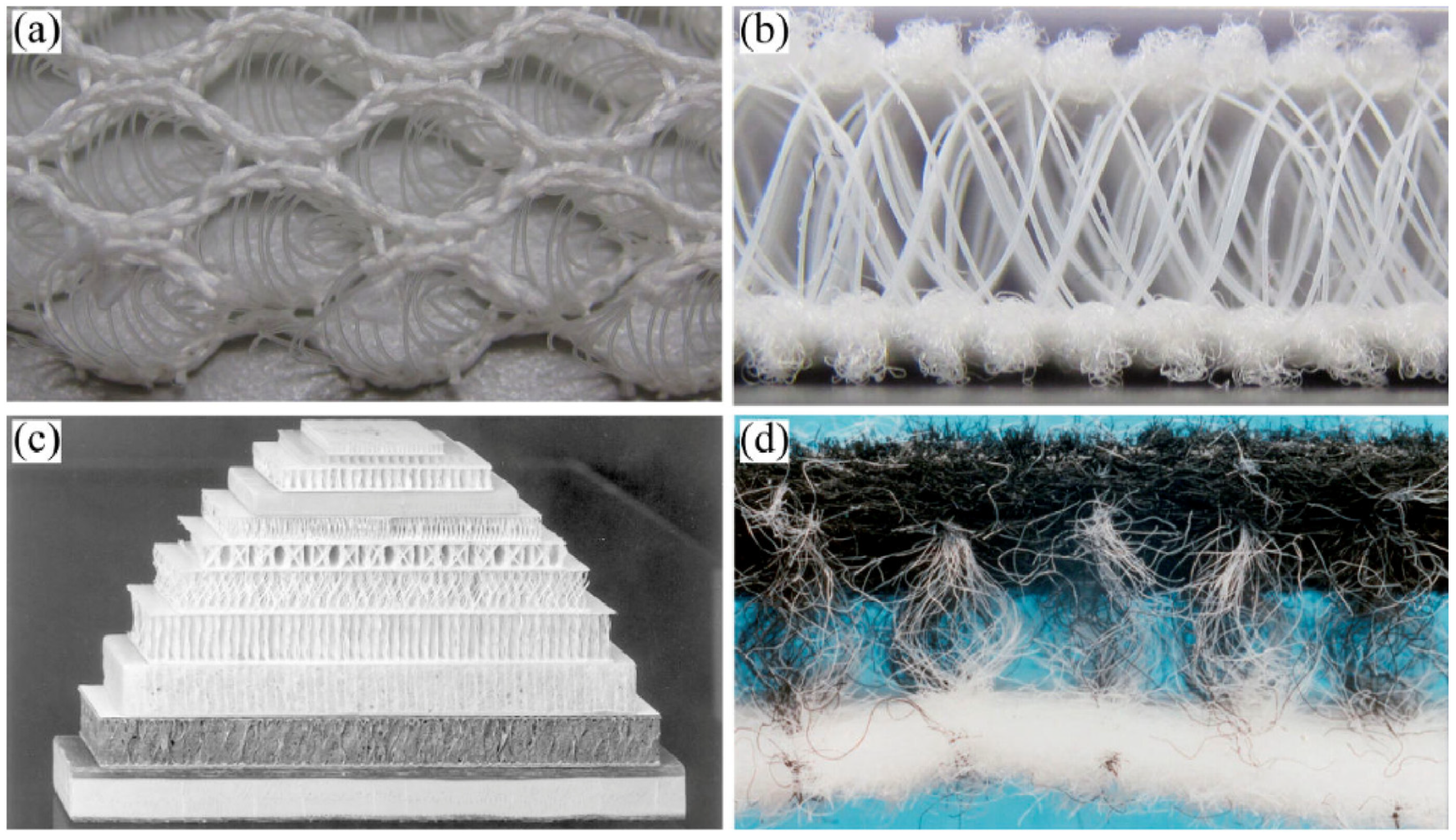
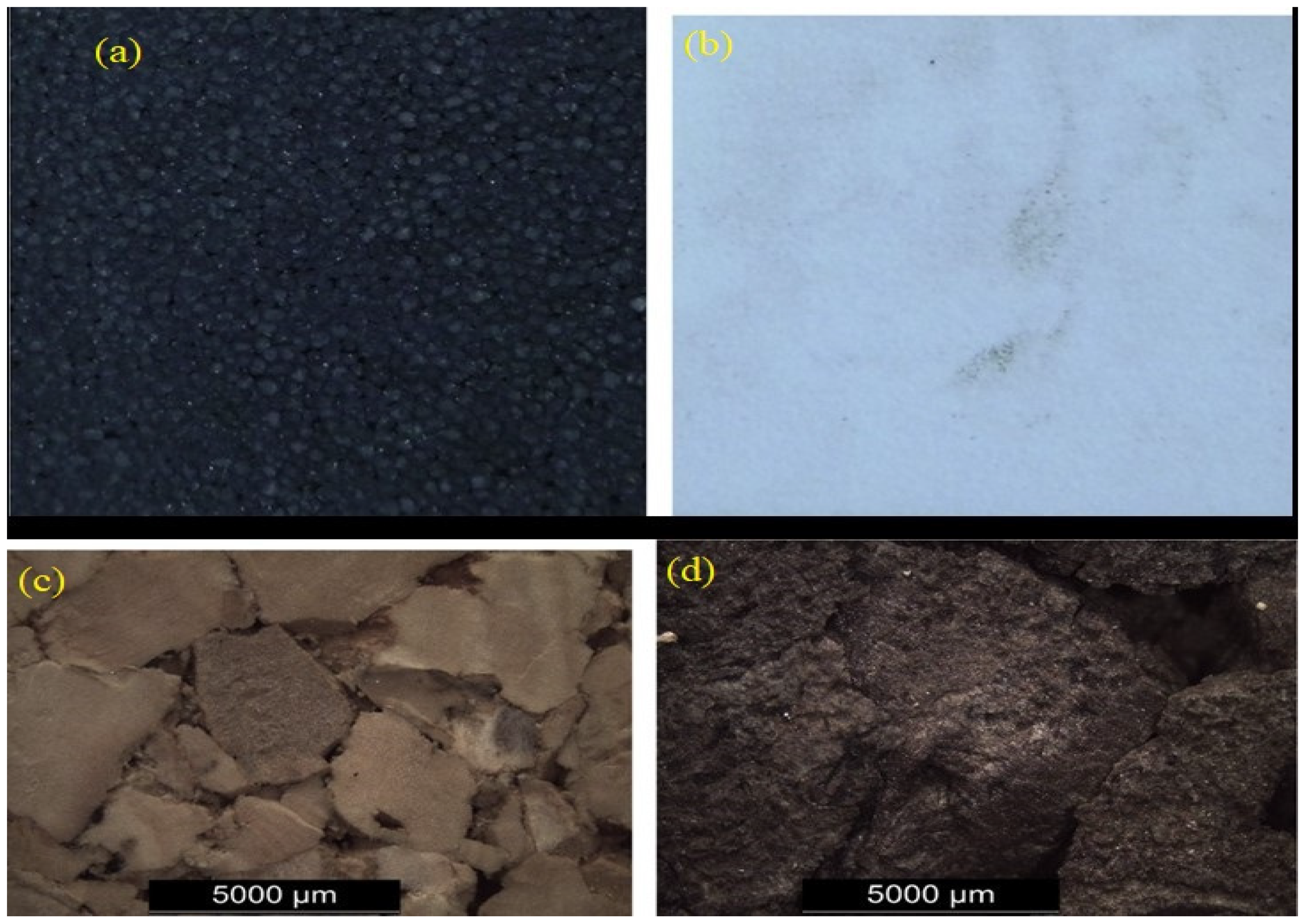
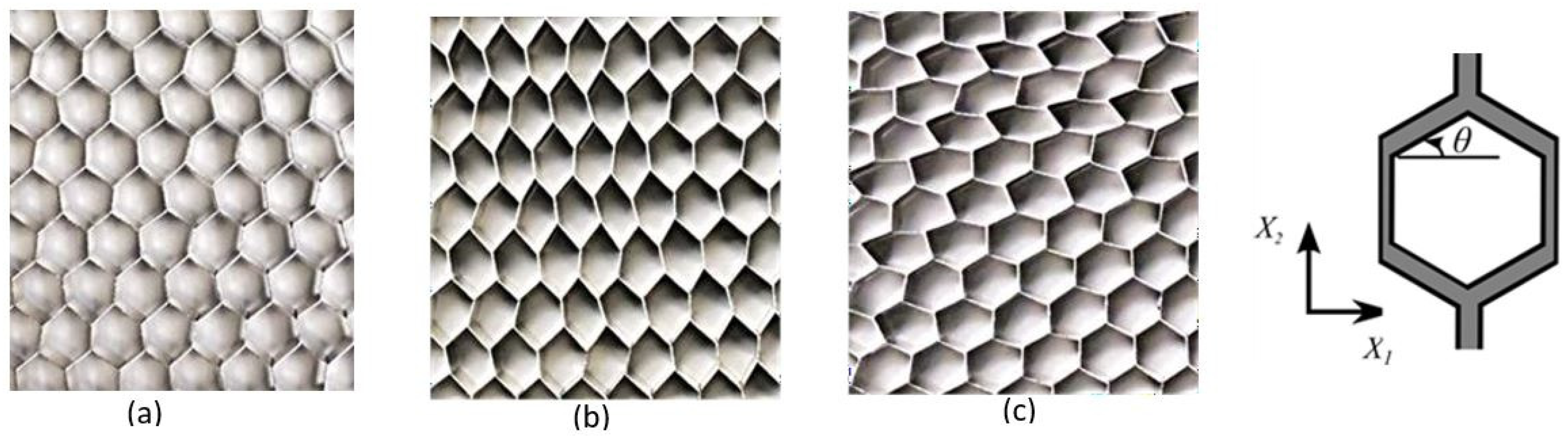
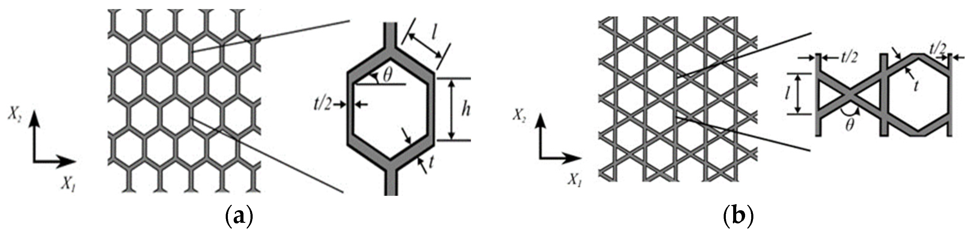
2. Microstructure of Cellular Material

| Types of Material | Geometry Features | Imperfection Range | References |
|---|---|---|---|
| Architected Cellular | Overlapping nodes (Edge misalignment, Node displacement) | Variable | [112] |
| Porous Metals | Void distribution (Pore aspect ratio, Pore alignment) | Variable | [113] |
| Foams | Cell size variation (Cell shape deviation, Cell wall thickness) | Variable | [114] |
| Wood-Based Composites | Fiber orientation (Fiber diameter, Fiber length) | Variable | [65] |
| Carbon Aerogel | Pore size distribution (Pore connectivity, Wall thickness) | Variable | [115] |
3. Homogenization Methodology
- in linear elastic region:
- plateau region:
- and also densification region:
4. Experimental Works and Some Manufacturing Method
5. Computer Simulations
6. Uncertainty Analysis Aspects
7. Discussion
8. Concluding Remarks
Funding
Conflicts of Interest
References
- Rostami-Tapeh-Esmaeil, E.; Rodrigue, D. Morphological, Mechanical and Thermal Properties of Rubber Foams: A Review Based on Recent Investigations. Materials 2023, 16, 1934. [Google Scholar] [CrossRef] [PubMed]
- Magazzù, A.; Marcuello, C. Investigation of Soft Matter Nanomechanics by Atomic Force Microscopy and Optical Tweezers: A Comprehensive Review. Nanomaterials 2023, 13, 963. [Google Scholar] [CrossRef] [PubMed]
- Bauer, J.; Hengsbach, S.; Tesari, I.; Schwaiger, R.; Kraft, O. High-Strength Cellular Ceramic Composites with 3D Microarchitecture. Proc. Natl. Acad. Sci. USA 2014, 111, 2453–2458. [Google Scholar] [CrossRef] [PubMed]
- Niu, B.; Yan, J.; Cheng, G. Optimum Structure with Homogeneous Optimum Cellular Material for Maximum Fundamental Frequency. Struct. Multidiscip. Optim. 2009, 39, 115–132. [Google Scholar] [CrossRef]
- Hillier, K. Cellular materials. In Handbook of Polymer Testing; CRC Press: Boca Raton, FL, USA, 2020; pp. 389–454. [Google Scholar] [CrossRef]
- Mohsenizadeh, M.; Gasbarri, F.; Munther, M.; Beheshti, A.; Davami, K. Additively-Manufactured Lightweight Metamaterials for Energy Absorption. Mater. Des. 2018, 139, 521–530. [Google Scholar] [CrossRef]
- Li, D.; Liao, W.; Dai, N.; Xie, Y.M. Comparison of Mechanical Properties and Energy Absorption of Sheet-Based and Strut-Based Gyroid Cellular Structures with Graded Densities. Materials 2019, 12, 2183. [Google Scholar] [CrossRef] [PubMed]
- Ajdari, A.; Babaee, S.; Vaziri, A. Mechanical Properties and Energy Absorption of Heterogeneous and Functionally Graded Cellular Structures. Procedia Eng. 2011, 10, 219–223. [Google Scholar] [CrossRef]
- Wang, G.; Zhao, J.; Wang, G.; Mark, L.H.; Park, C.B.; Zhao, G. Low-Density and Structure-Tunable Microcellular PMMA Foams with Improved Thermal-Insulation and Compressive Mechanical Properties. Eur. Polym. J. 2017, 95, 382–393. [Google Scholar] [CrossRef]
- Prabhu, S.; Raja, V.K.B.; Nikhil, R. Applications of Cellular Materials—An Overview. Appl. Mech. Mater. 2015, 766, 511–517. [Google Scholar] [CrossRef]
- Vesenjak, M.; Krstulović-Opara, L.; Ren, Z.; Öchsner, A.; Domazet, Ž. Experimental Study of Open-Cell Cellular Structures with Elastic Filler Material. Exp. Mech. 2009, 49, 501–509. [Google Scholar] [CrossRef]
- Baroutaji, A.; Arjunan, A.; Niknejad, A.; Tran, T.; Olabi, A.-G. Application of Cellular Material in Crashworthiness Applications: An Overview. In Reference Module in Materials Science and Materials Engineering; Elsevier: Amsterdam, The Netherlands, 2019. [Google Scholar] [CrossRef]
- Prajapati, M.J.; Kumar, A.; Lin, S.C.; Jeng, J.Y. Multi-Material Additive Manufacturing with Lightweight Closed-Cell Foam-Filled Lattice Structures for Enhanced Mechanical and Functional Properties. Addit. Manuf. 2022, 54, 102766. [Google Scholar] [CrossRef]
- Compton, B.G.; Lewis, J.A. 3D-printing of Lightweight Cellular Composites. Adv. Mater. 2014, 26, 5930–5935. [Google Scholar] [CrossRef]
- Ongaro, F.; De Falco, P.; Barbieri, E.; Pugno, N.M. Mechanics of Filled Cellular Materials. Mech. Mater. 2016, 97, 26–47. [Google Scholar] [CrossRef]
- Mehta, G. Biocomposites from Engineered Natural Fibers and Unsaturated Polyester Resin for Housing Panel Applications; Michigan State University: East Lansing, MI, USA, 2005. [Google Scholar]
- Cadman, J.; Chang, C.C.; Chen, J.; Chen, Y.; Zhou, S.; Li, W.; Li, Q. Bioinspired Lightweight Cellular Materials—Understanding Effects of Natural Variation on Mechanical Properties. Mater. Sci. Eng. C 2013, 33, 3146–3152. [Google Scholar] [CrossRef] [PubMed]
- Xu, Y.; Shi, W.; Liu, M. Dual-Gradient Structure of Natural Cellular Materials for the Design of Auxetic Metamaterials. Sci. China Mater. 2023, 66, 3022–3025. [Google Scholar] [CrossRef]
- Borbon-Almada, A.C.; Lucero-Alvarez, J.; Rodriguez-Muñoz, N.A.; Ramirez-Celaya, M.; Castro-Brockman, S.; Sau-Soto, N.; Najera-Trejo, M. Design and Application of Cellular Concrete on a Mexican Residential Building and Its Influence on Energy Savings in Hot Climates: Projections to 2050. Appl. Sci. 2020, 10, 8225. [Google Scholar] [CrossRef]
- Alsakka, F.; Haddad, A.; Ezzedine, F.; Salami, G.; Dabaghi, M.; Hamzeh, F. Generative Design for More Economical and Environmentally Sustainable Reinforced Concrete Structures. J. Clean. Prod. 2023, 387, 135829. [Google Scholar] [CrossRef]
- Valdevit, L.; Jacobsen, A.J.; Greer, J.R.; Carter, W.B. Protocols for the Optimal Design of Multi-Functional Cellular Structures: From Hypersonics to Micro-Architected Materials. J. Am. Ceram. Soc. 2011, 94, s15–s34. [Google Scholar] [CrossRef]
- Zhang, Y.; Gao, L.; Xiao, M. Maximizing Natural Frequencies of Inhomogeneous Cellular Structures by Kriging-Assisted Multiscale Topology Optimization. Comput. Struct. 2020, 230, 106197. [Google Scholar] [CrossRef]
- Nguyen, V.D. Computational Homogenization of Cellular Materials Capturing Micro–Buckling, Macro–Localization and Size Effects. 2014, pp. 1–115. Available online: https://hdl.handle.net/2268/159953 (accessed on 20 April 2024).
- Huang, X.; Zhou, S.W.; Xie, Y.M.; Li, Q. Topology Optimization of Microstructures of Cellular Materials and Composites for Macrostructures. Comput. Mater. Sci. 2013, 67, 397–407. [Google Scholar] [CrossRef]
- Gibson, L.J. ASHBY MF Cellular Solids: Structure and Properties; Cambridge University Press: Cambridge, UK, 1997. [Google Scholar]
- Amran, Y.H.M.; Farzadnia, N.; Ali, A.A.A. Properties and Applications of Foamed Concrete; A Review. Constr. Build. Mater. 2015, 101, 990–1005. [Google Scholar] [CrossRef]
- Banhart, J. Manufacture, Characterisation and Application of Cellular Metals and Metal Foams. Prog. Mater. Sci. 2001, 46, 559–632. [Google Scholar] [CrossRef]
- Sun, G.; Chen, D.; Zhu, G.; Li, Q. Lightweight Hybrid Materials and Structures for Energy Absorption: A State-of-the-Art Review and Outlook. Thin-Walled Struct. 2022, 172, 108760. [Google Scholar] [CrossRef]
- Ajdari, A.; Nayeb-Hashemi, H.; Vaziri, A. Dynamic Crushing and Energy Absorption of Regular, Irregular and Functionally Graded Cellular Structures. Int. J. Solids Struct. 2011, 48, 506–516. [Google Scholar] [CrossRef]
- Dziewit, P.; Platek, P.; Janiszewski, J.; Sarzynski, M.; Grazka, M.; Paszkowski, R. Mechanical Response of Additive Manufactured Regular Cellular Structures in Quasi-Static Loading Conditions—Part I Experimental Investigations. In Proceedings of the 7th International Conference on Mechanics and Materials in Design, Albufeira, Portugal, 11–15 June 2017; pp. 1061–1074. [Google Scholar]
- Evans, A.G.; Hutchinson, J.W.; Fleck, N.A.; Ashby, M.F.; Wadley, H.N.G. The Topological Design of Multifunctional Cellular Metals. Prog. Mater. Sci. 2001, 46, 309–327. [Google Scholar] [CrossRef]
- Bodaghi, M.; Damanpack, A.R.; Hu, G.F.; Liao, W.H. Large Deformations of Soft Metamaterials Fabricated by 3D Printing. Mater. Des. 2017, 131, 81–91. [Google Scholar] [CrossRef]
- Tanlak, N.; De Lange, D.F.; Van Paepegem, W. Numerical Prediction of the Printable Density Range of Lattice Structures for Additive Manufacturing. Mater. Des. 2017, 133, 549–558. [Google Scholar] [CrossRef]
- Ohno, N.; Okumura, D.; Noguchi, H. Microscopic Symmetric Bifurcation Condition of Cellular Solids Based on a Homogenization Theory of Finite Deformation. J. Mech. Phys. Solids 2002, 50, 1125–1153. [Google Scholar] [CrossRef]
- Nguyen, V.D.; Noels, L. Computational Homogenization of Cellular Materials. Int. J. Solids Struct. 2014, 51, 2183–2203. [Google Scholar] [CrossRef]
- Iyer, S.; Alkhader, M.; Venkatesh, T.A. On the Relationships between Cellular Structure, Deformation Modes and Electromechanical Properties of Piezoelectric Cellular Solids. Int. J. Solids Struct. 2016, 80, 73–83. [Google Scholar] [CrossRef]
- Rajakareyar, P.; ElSayed, M.S.A.; Abo El Ella, H.; Matida, E. Effective Mechanical Properties of Periodic Cellular Solids with Generic Bravais Lattice Symmetry via Asymptotic Homogenization. Materials 2023, 16, 7562. [Google Scholar] [CrossRef] [PubMed]
- Restrepo, D.; Mankame, N.D.; Zavattieri, P.D. Programmable Materials Based on Periodic Cellular Solids. Part I: Experiments. Int. J. Solids Struct. 2016, 100, 485–504. [Google Scholar] [CrossRef]
- Chai, H.W.; Xie, Z.L.; Xiao, X.H.; Xie, H.L.; Huang, J.Y.; Luo, S.N. Microstructural Characterization and Constitutive Modeling of Deformation of Closed-Cell Foams Based on in Situ x-Ray Tomography. Int. J. Plast. 2020, 131, 102730. [Google Scholar] [CrossRef]
- Tai, Y.; Banerjee, A.; Goodrich, R.; Jin, L.; Nam, J. Development and Utilization of Multifunctional Polymeric Scaffolds for the Regulation of Physical Cellular Microenvironments. Polymers 2021, 13, 3880. [Google Scholar] [CrossRef] [PubMed]
- Zheng, Z.; Wang, C.; Yu, J.; Reid, S.R.; Harrigan, J.J. Dynamic Stress-Strain States for Metal Foams Using a 3D Cellular Model. J. Mech. Phys. Solids 2014, 72, 93–114. [Google Scholar] [CrossRef]
- Moiseenko, D.D.; Panin, S.V.; Maksimov, P.V.; Iriskina, E.N.; Goryacheva, I.G. Simulation of Mechanical Loading by Cylindrical Indenter of “Ceramic Coating—Polycrystalline Metallic Substrate” Composition. In Proceedings of the 19th European Conference on Fracture: Fracture Mechanics for Durability, Reliability and Safety, ECF 2012, Kazan, Russia, 26–31 August 2012. [Google Scholar]
- An, X.; Lai, C.; Fan, H.; Zhang, C. 3D Acoustic Metamaterial-Based Mechanical Metalattice Structures for Low-Frequency and Broadband Vibration Attenuation. Int. J. Solids Struct. 2020, 191, 293–306. [Google Scholar] [CrossRef]
- Li, J.; Zhang, X.; An, S.; Zhu, Z.; Deng, Z.; You, Z. Kirigami-Inspired Foldable 3D Cellular Structures with a Single Degree of Freedom. Int. J. Solids Struct. 2022, 244, 111587. [Google Scholar] [CrossRef]
- Gibson, L.J.; Tonyan, T.D. Microstructural Design of Cellular Materials. Am. Soc. Mech. Eng. Mater. Div. (Publ.) MD 1992, 38, 1–13. [Google Scholar]
- Redenbach, C. Microstructure Models for Cellular Materials. Comput. Mater. Sci. 2009, 44, 1397–1407. [Google Scholar] [CrossRef]
- Ling, C.; Ivens, J.; Cardiff, P.; Gilchrist, M.D. Deformation Response of EPS Foam under Combined Compression-Shear Loading. Part II: High Strain Rate Dynamic Tests. Int. J. Mech. Sci. 2018, 145, 9–23. [Google Scholar] [CrossRef]
- Ling, C.; Ivens, J.; Cardiff, P.; Gilchrist, M.D. Deformation Response of EPS Foam under Combined Compression-Shear Loading. Part I: Experimental Design and Quasi-Static Tests. Int. J. Mech. Sci. 2018, 144, 480–489. [Google Scholar] [CrossRef]
- Zargarian, A.; Esfahanian, M.; Kadkhodapour, J.; Ziaei-Rad, S. Effect of Solid Distribution on Elastic Properties of Open-Cell Cellular Solids Using Numerical and Experimental Methods. J. Mech. Behav. Biomed. Mater. 2014, 37, 264–273. [Google Scholar] [CrossRef] [PubMed]
- Avalle, M.; Belingardi, G.; Ibba, A. Mechanical Models of Cellular Solids: Parameters Identification from Experimental Tests. Int. J. Impact Eng. 2007, 34, 3–27. [Google Scholar] [CrossRef]
- Arregui-Mena, J.D.; Margetts, L.; Mummery, P.M. Practical Application of the Stochastic Finite Element Method. Arch. Comput. Methods Eng. 2016, 23, 171–190. [Google Scholar] [CrossRef]
- Ding, C.; Hu, X.; Cui, X.; Li, G.; Cai, Y.; Tamma, K.K. Isogeometric Generalized n Th Order Perturbation-Based Stochastic Method for Exact Geometric Modeling of (Composite) Structures: Static and Dynamic Analysis with Random Material Parameters. Comput. Methods Appl. Mech. Eng. 2019, 346, 1002–1024. [Google Scholar] [CrossRef]
- Mesogitis, T.S.; Skordos, A.A.; Long, A.C. Uncertainty in the Manufacturing of Fibrous Thermosetting Composites: A Review. Compos. Part A Appl. Sci. Manuf. 2014, 57, 67–75. [Google Scholar] [CrossRef]
- Beckmann, C.; Hohe, J. A Probabilistic Constitutive Model for Closed-Cell Foams. Mech. Mater. 2016, 96, 96–105. [Google Scholar] [CrossRef]
- A Probabilistic Model for Machine Cell Formation. J. Manuf. Syst. 1993, 12, 73. [CrossRef]
- Alonso Atienza, F.; Requena Carrión, J.; García Alberola, A.; Rojo Álvarez, J.L.; SÁnchez Muñoz, J.J.; Martínez SÁnchez, J.; Valdés Chávarri, M. A Probabilistic Model of Cardiac Electrical Activity Based on a Cellular Automata System. Rev. Española De Cardiol. 2005, 58, 41–47. [Google Scholar] [CrossRef]
- Zhu, L.; Lyu, L.; Zhang, X.; Wang, Y.; Guo, J.; Xiong, X. Bending Properties of Zigzag-Shaped 3D Woven Spacer Composites: Experiment and FEM Simulation. Materials 2019, 12, 1075. [Google Scholar] [CrossRef]
- Wu, G.; Shen, Y.; Fu, F.; Guo, J.; Ren, H. Study of the Mechanical Properties of Wood under Transverse Compression Using Monto Carlo Simulation-Based Stochastic FE Analysis. Forests 2022, 13, 32. [Google Scholar] [CrossRef]
- Ni, C.C. Verification of a Polynomial Stochastic Fatigue Crack Growth Model. In Proceedings of the 2015 International Conference on Intelligent Systems Research and Mechatronics Engineering, Zhengzhou, China, 11–13 April 2015; Atlantis Press: Amsterdam, The Netherlands, 2015; pp. 2215–2220. [Google Scholar] [CrossRef]
- Daxner, T. Finite Element Modeling of Cellular Materials. CISM Int. Cent. Mech. Sci. Courses Lect. 2010, 521, 47–106. [Google Scholar] [CrossRef] [PubMed]
- Spear, D.G.; Palazotto, A.N. Testing and Modeling of Cellular Materials. In Testing and Modeling of Cellular Materials; CRC Press: Boca Raton, FL, USA, 2022; pp. 1–184. [Google Scholar] [CrossRef]
- Ghaffarizadeh, A.; Heiland, R.; Friedman, S.H.; Mumenthaler, S.M.; Macklin, P. PhysiCell: An Open Source Physics-Based Cell Simulator for 3-D Multicellular Systems. PLoS Comput. Biol. 2018, 14, e1005991. [Google Scholar] [CrossRef] [PubMed]
- Rege, A. Constitutive Modeling of the Densification Behavior in Open-Porous Cellular Solids. Materials 2021, 14, 2731. [Google Scholar] [CrossRef] [PubMed]
- Groth, J.H.; Anderson, C.; Magnini, M.; Tuck, C.; Clare, A. Five Simple Tools for Stochastic Lattice Creation. Addit. Manuf. 2022, 49, 102488. [Google Scholar] [CrossRef]
- Bhate, D.; Penick, C.A.; Ferry, L.A.; Lee, C. Classification and Selection of Cellular Materials in Mechanical Design: Engineering and Biomimetic Approaches. Designs 2019, 3, 19. [Google Scholar] [CrossRef]
- Bogunia, L.; Buchen, S.; Weinberg, K. Microstructure Characterization and Stochastic Modeling of Open-Cell Foam Based on ΜCT-Image Analysis. GAMM Mitteilungen 2022, 45, e202200018. [Google Scholar] [CrossRef]
- Wu, Y.; Yang, L. Modeling of the Effect of Local Material Imperfection to the Structural Mechanical Property Variability of 2D Finite-Size Cellular Structures. Compos. Struct. 2021, 262, 113610. [Google Scholar] [CrossRef]
- Polymer Technologies, Inc. Open vs. Closed Cell Foam: Understanding Permeability. Available online: https://blog.polytechinc.com/open-vs-closed-cell-foam-article/ (accessed on 24 August 2018).
- Kaoua, S.A.; Boutaleb, S.; Dahmoun, D.; Azzaz, M. Numerical Modelling of Open-Cell Metal Foam with Kelvin Cell. Comput. Appl. Math. 2016, 35, 977–985. [Google Scholar] [CrossRef]
- Baillis, D.C.R.K.A. Classification of Foam Structures. In Thermopedia; Begel House Inc.: Danbury, CT, USA, 2012. [Google Scholar]
- Amatriain, A.; Gargiulo, C.; Rubio, G. Numerical and Experimental Study of Open-Cell Foams for the Characterization of Heat Exchangers. Int. J. Heat Mass Transf. 2023, 217, 124701. [Google Scholar] [CrossRef]
- Tiger Foam Insulation Open Cell vs. Closed Cell Foam: Which Should I Choose? Available online: https://tigerfoam.com/sprayfoaminsulation/open-cell-vs-closed-cell-foam-which-should-i-choose/ (accessed on 27 July 2019).
- Baillis, D.; Coquard, R.; Cunsolo, S. Effective Conductivity of Voronoi’s Closed- and Open-Cell Foams: Analytical Laws and Numerical Results. J. Mater. Sci. 2017, 52, 11146–11167. [Google Scholar] [CrossRef]
- Wu, G.; Xie, P.; Yang, H.; Dang, K.; Xu, Y.; Sain, M.; Turng, L.S.; Yang, W. A Review of Thermoplastic Polymer Foams for Functional Applications. J. Mater. Sci. 2021, 56, 11579–11604. [Google Scholar] [CrossRef]
- Balit, Y.; Charkaluk, E.; Constantinescu, A. Digital Image Correlation for Microstructural Analysis of Deformation Pattern in Additively Manufactured 316L Thin Walls. Addit. Manuf. 2020, 31, 100862. [Google Scholar] [CrossRef]
- Novak, N.; Biasetto, L.; Rebesan, P.; Zanini, F.; Carmignato, S.; Krstulović-Opara, L.; Vesenjak, M.; Ren, Z. Experimental and Computational Evaluation of Tensile Properties of Additively Manufactured Hexa- and Tetrachiral Auxetic Cellular Structures. Addit. Manuf. 2021, 45, 102022. [Google Scholar] [CrossRef]
- Veyhl, C.; Belova, I.V.; Murch, G.E.; Fiedler, T. Finite Element Analysis of the Mechanical Properties of Cellular Aluminium Based on Micro-Computed Tomography. Mater. Sci. Eng. A 2011, 528, 4550–4555. [Google Scholar] [CrossRef]
- Kadkhodapour, J.; Raeisi, S. Micro-Macro Investigation of Deformation and Failure in Closed-Cell Aluminum Foams. Comput. Mater. Sci. 2014, 83, 137–148. [Google Scholar] [CrossRef]
- Luxner, M.H.; Woesz, A.; Stampfl, J.; Fratzl, P.; Pettermann, H.E. A Finite Element Study on the Effects of Disorder in Cellular Structures. Acta Biomater. 2009, 5, 381–390. [Google Scholar] [CrossRef]
- Lu, Y.; Tong, L. Concurrent Topology Optimization of Cellular Structures and Anisotropic Materials. Comput. Struct. 2021, 255, 106624. [Google Scholar] [CrossRef]
- Wei, C.; Zhang, Z.; Cheng, D.; Sun, Z.; Zhu, M.; Li, L. An Overview of Laser-Based Multiple Metallic Material Additive Manufacturing: From Macro: From Micro-Scales. Int. J. Extrem. Manuf. 2021, 3, 012003. [Google Scholar] [CrossRef]
- Wang, Z.; Huang, C.; Han, X.; Li, S.; Wang, Z.; Huang, J.; Liu, H.; Chen, Z. Fabrication of Aerogel Scaffolds with Adjustable Macro/Micro-Pore Structure through 3D Printing and Sacrificial Template Method for Tissue Engineering. Mater. Des. 2022, 217, 110662. [Google Scholar] [CrossRef]
- Ghazi, A.; Berke, P.; Tiago, C.; Massart, T.J. Computed Tomography Based Modelling of the Behaviour of Closed Cell Metallic Foams Using a Shell Approximation. Mater. Des. 2020, 194, 108866. [Google Scholar] [CrossRef]
- Andrews, E.; Sanders, W.; Gibson, L.J. Compressive and Tensile Behaviour of Aluminum Foams. Mater. Sci. Eng. A 1999, 270, 113–124. [Google Scholar] [CrossRef]
- Schaedler, T.A.; Carter, W.B. Architected Cellular Materials. Annu. Rev. Mater. Res. 2016, 46, 187–210. [Google Scholar] [CrossRef]
- Łach, Ł. Modeling of Microstructure Evolution during Deformation Processes by Cellular Automata—Boundary Conditions and Space Reorganization Aspects. Materials 2021, 14, 1377. [Google Scholar] [CrossRef] [PubMed]
- Zhang, Z.; Tan, Z.J.; Yao, X.X.; Hu, C.P.; Ge, P.; Wan, Z.Y.; Li, J.Y.; Wu, Q. Numerical Methods for Microstructural Evolutions in Laser Additive Manufacturing. Comput. Math. Appl. 2019, 78, 2296–2307. [Google Scholar] [CrossRef]
- Guddati, S.; Kiran, A.S.K.; Leavy, M.; Ramakrishna, S. Recent Advancements in Additive Manufacturing Technologies for Porous Material Applications. Int. J. Adv. Manuf. Technol. 2019, 105, 193–215. [Google Scholar] [CrossRef]
- Seibert, P.; Raßloff, A.; Zhang, Y.; Kalina, K.; Reck, P.; Peterseim, D.; Kästner, M. Reconstructing Microstructures from Statistical Descriptors Using Neural Cellular Automata. Integr. Mater. Manuf. Innov. 2024, 13, 272–287. [Google Scholar] [CrossRef]
- Chen, W.; Xia, L.; Yang, J.; Huang, X. Optimal Microstructures of Elastoplastic Cellular Materials under Various Macroscopic Strains. Mech. Mater. 2018, 118, 120–132. [Google Scholar] [CrossRef]
- Huang, X.; Radman, A.; Xie, Y.M. Topological Design of Microstructures of Cellular Materials for Maximum Bulk or Shear Modulus. Comput. Mater. Sci. 2011, 50, 1861–1870. [Google Scholar] [CrossRef]
- Huang, L.; Liu, X.; Liu, X.; Zhao, X. Analytical Homogenization for Equivalent In-Plane Elastic Moduli of Multi-Material Honeycombs. Compos. Struct. 2023, 325, 117586. [Google Scholar] [CrossRef]
- Pais, A.I.; Belinha, J.; Alves, J.L. Advances in Computational Techniques for Bio-Inspired Cellular Materials in the Field of Biomechanics: Current Trends and Prospects. Materials 2023, 16, 3946. [Google Scholar] [CrossRef]
- Yazdanparast, R.; Rafiee, R. Determining In-Plane Material Properties of Square Core Cellular Materials Using Computational Homogenization Technique. Eng. Comput. 2023, 39, 373–386. [Google Scholar] [CrossRef]
- Duarte, I.; Fiedler, T.; Krstulović-Opara, L.; Vesenjak, M. Brief Review on Experimental and Computational Techniques for Characterization of Cellular Metals. Metals 2020, 10, 726. [Google Scholar] [CrossRef]
- Pilania, G.; Goldsmith, B.R.; Yoon, M.; Dongare, A.M. Recent Advances in Computational Materials Design: Methods, Applications, Algorithms, and Informatics. J. Mater. Sci. 2022, 57, 10471–10474. [Google Scholar] [CrossRef] [PubMed]
- Caty, O.; Maire, E.; Youssef, S.; Bouchet, R. Modeling the Properties of Closed-Cell Cellular Materials from Tomography Images Using Finite Shell Elements. Acta Mater. 2008, 56, 5524–5534. [Google Scholar] [CrossRef]
- Fiedler, T.; Ochsner, A.; Gracio, J.; Kuhn, G. Structural Modeling of the Mechanical Behavior of Periodic Cellular Solids: Open-Cell Structures. Mech. Compos. Mater. 2005, 41, 277–290. [Google Scholar] [CrossRef]
- Kucewicz, M.; Baranowski, P.; Małachowski, J.; Popławski, A.; Płatek, P. Modelling, and Characterization of 3D Printed Cellular Structures. Mater. Des. 2018, 142, 177–189. [Google Scholar] [CrossRef]
- Ji, G.; Huber, J. Recent Progress in Acoustic Metamaterials and Active Piezoelectric Acoustic Metamaterials—A Review. Appl. Mater. Today 2022, 26, 101260. [Google Scholar] [CrossRef]
- Liao, G.; Luan, C.; Wang, Z.; Liu, J.; Yao, X.; Fu, J. Acoustic Metamaterials: A Review of Theories, Structures, Fabrication Approaches, and Applications. Adv. Mater. Technol. 2021, 6, 2000787. [Google Scholar] [CrossRef]
- Thomson, W. LXIV. On the Application of the Deci-Ampere or the Centiampere Balance to the Determination of the Electromotive Forces of Voltaic Cells. Lond. Edinb. Dublin Philos. Mag. J. Sci. 1887, 24, 514–516. [Google Scholar] [CrossRef]
- Weaire, D.; Phelan, R. A Counter-Example to Kelvin’s Conjecture on Minimal Surfaces. Philos. Mag. Lett. 1994, 69, 107–110. [Google Scholar] [CrossRef]
- Neje, G.; Behera, B.K. Investigation of Mechanical Performance of 3D Woven Spacer Sandwich Composites with Different Cell Geometries. Compos. Part B Eng. 2019, 160, 306–314. [Google Scholar] [CrossRef]
- Dejene, B.K.; Gudayu, A.D. Exploring the Potential of 3D Woven and Knitted Spacer Fabrics in Technical Textiles: A Critical Review. J. Ind. Text. 2024, 54, 15280837241253614. [Google Scholar] [CrossRef]
- Fernandes, F.A.O.; Jardin, R.T.; Pereira, A.B.; Alves de Sousa, R.J. Comparing the Mechanical Performance of Synthetic and Natural Cellular Materials. Mater. Des. 2015, 82, 335–341. [Google Scholar] [CrossRef]
- Gioux, G.; McCormack, T.M.; Gibson, L.J. Failure of Aluminum Foams under Multiaxial Loads. Int. J. Mech. Sci. 2000, 42, 1097–1117. [Google Scholar] [CrossRef]
- Sugimura, Y.; Meyer, J.; He, M.Y.; Bart-Smith, H.; Grenstedt, J.; Evans, A.G. On the Mechanical Performance of Closed Cell Al Alloy Foams. Acta Mater. 1997, 45, 5245–5259. [Google Scholar] [CrossRef]
- Evans, A.G.; Hutchinson, J.W.; Ashby, M.F. Multifunctionality of Cellular Metal Systems. Prog. Mater. Sci. 1998, 43, 171–221. [Google Scholar] [CrossRef]
- Lendlein, A.; Kelch, S. Shape-Memory Polymers. Angew. Chem. Int. Ed. 2002, 41, 2034–2057. [Google Scholar] [CrossRef]
- Tobushi, H.; Shimada, D.; Hayashi, S.; Endo, M. Shape Fixity and Shape Recovery of Polyurethane Shape-Memory Polymer Foams. Proc. Inst. Mech. Eng. Part L J. Mater. Des. Appl. 2003, 217, 135–143. [Google Scholar] [CrossRef]
- Benedetti, M.; du Plessis, A.; Ritchie, R.O.; Dallago, M.; Razavi, N.; Berto, F. Architected Cellular Materials: A Review on Their Mechanical Properties towards Fatigue-Tolerant Design and Fabrication. Mater. Sci. Eng. R Rep. 2021, 144, 100606. [Google Scholar] [CrossRef]
- Dallago, M.; Winiarski, B.; Zanini, F.; Carmignato, S.; Benedetti, M. On the Effect of Geometrical Imperfections and Defects on the Fatigue Strength of Cellular Lattice Structures Additively Manufactured via Selective Laser Melting. Int. J. Fatigue 2019, 124, 348–360. [Google Scholar] [CrossRef]
- Ha, C.S.; Hsieh, M.T. The Effect of Geometric Imperfections on the Mechanical Response of Isotropic Closed-Cell Plate Lattices. Mech. Res. Commun. 2023, 128, 104073. [Google Scholar] [CrossRef]
- Luo, G.; Zhu, Y.; Zhang, R.; Cao, P.; Liu, Q.; Zhang, J.; Sun, Y.; Yuan, H.; Guo, W.; Shen, Q.; et al. A Review on Mechanical Models for Cellular Media: Investigation on Material Characterization and Numerical Simulation. Polymers 2021, 13, 3283. [Google Scholar] [CrossRef] [PubMed]
- Vigliotti, A.; Pasini, D. Stiffness and Strength of Tridimensional Periodic Lattices. Comput. Methods Appl. Mech. Eng. 2012, 229, 27–43. [Google Scholar] [CrossRef]
- Andreassen, E.; Andreasen, C.S. How to Determine Composite Material Properties Using Numerical Homogenization. Comput. Mater. Sci. 2014, 83, 488–495. [Google Scholar] [CrossRef]
- Hassani, B.; Hinton, E. A Review of Homogenization and Topology Optimization I—Homogenization Theory for Media with Periodic Structure. Comput. Struct. 1998, 69, 707–717. [Google Scholar] [CrossRef]
- Hollister, S.J.; Kikuchi, N. A Comparison of Homogenization and Standard Mechanics Analyses for Periodic Porous Composites. Comput. Mech. 1992, 10, 73–95. [Google Scholar] [CrossRef]
- Guedes, J.; Kikuchi, N. Preprocessing and Postprocessing for Materials Based on the Homogenization Method with Adaptive Finite Element Methods. Comput. Methods Appl. Mech. Eng. 1990, 83, 143–198. [Google Scholar] [CrossRef]
- Hassani, B.; Hinton, E. A Review of Homogenization and Topology Opimization II—Analytical and Numerical Solution of Homogenization Equations. Comput. Struct. 1998, 69, 719–738. [Google Scholar] [CrossRef]
- Hassani, B.; Hinton, E. A Review of Homogenization and Topology Optimization III—Topology Optimization Using Optimality Criteria. Comput. Struct. 1998, 69, 739. [Google Scholar] [CrossRef]
- Bleyer, J. Multiphase Model for Fiber-Reinforced Materials. Researchgate. 2020. Available online: https://www.researchgate.net/publication/341359306_Multiphase_model_for_fiber-reinforced_materials (accessed on 20 April 2024).
- Radman, A. Combination of BESO and Harmony Search for Topology Optimization of Microstructures for Materials. Appl. Math. Model. 2021, 90, 650–661. [Google Scholar] [CrossRef]
- Eren, O.; Sezer, H.K.; Yalçın, N. Effect of Lattice Design on Mechanical Response of PolyJet Additively Manufactured Cellular Structures. J. Manuf. Process. 2022, 75, 1175–1188. [Google Scholar] [CrossRef]
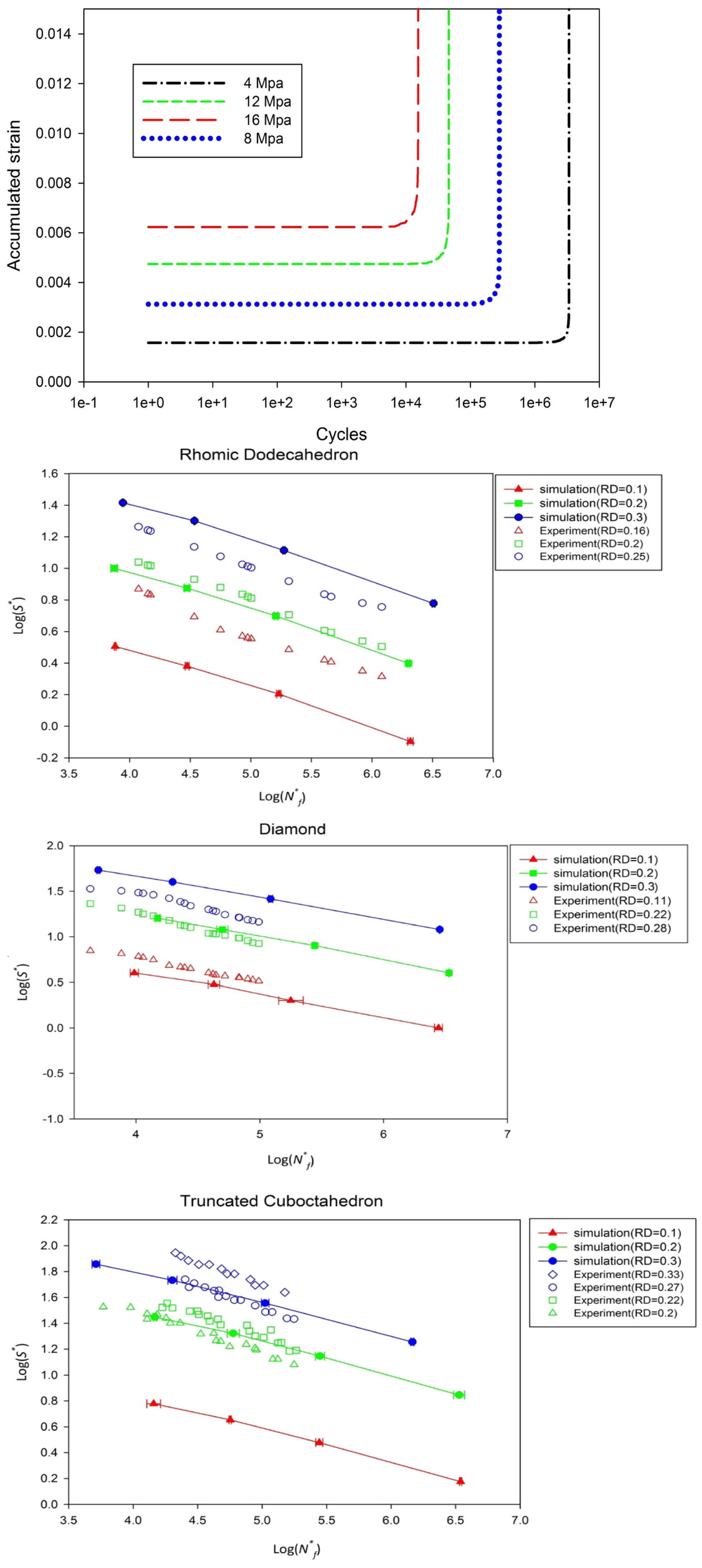
- Zargarian, A.; Esfahanian, M.; Kadkhodapour, J.; Ziaei-Rad, S. Numerical Simulation of the Fatigue Behavior of Additive Manufactured Titanium Porous Lattice Structures. Mater. Sci. Eng. C 2016, 60, 339–347. [Google Scholar] [CrossRef] [PubMed]
- Denavit, J.; Hartenberg, R.S. A Kinematic Notation for Lower-Pair Mechanisms Based on Matrices. J. Appl. Mech. 1955, 22, 215–221. [Google Scholar] [CrossRef]
- Huhdanpaa, H.; Barber, C.B.; Dobkin, D.P. The Quickhull Algorithm for Convex Hulls. ACM Trans. Math. Softw. 1996, 22, 469–483. [Google Scholar]
- Yang, H.; Wu, C.; Li, H.; Fan, X. Review on Cellular Automata Simulations of Microstructure Evolution during Metal Forming Process: Grain Coarsening, Recrystallization and Phase Transformation. Sci. China Technol. Sci. 2011, 54, 2107–2118. [Google Scholar] [CrossRef]
- Bai, L.; Gong, C.; Chen, X.; Sun, Y.; Xin, L.; Pu, H.; Peng, Y.; Luo, J. Mechanical Properties and Energy Absorption Capabilities of Functionally Graded Lattice Structures: Experiments and Simulations. Int. J. Mech. Sci. 2020, 182, 105735. [Google Scholar] [CrossRef]
- Korshunova, N.; Papaioannou, I.; Kollmannsberger, S.; Straub, D.; Rank, E. Uncertainty Quantification of Microstructure Variability and Mechanical Behavior of Additively Manufactured Lattice Structures. Comput. Methods Appl. Mech. Eng. 2021, 385, 114049. [Google Scholar] [CrossRef]
- Thillaithevan, D.; Bruce, P.; Santer, M. Robust Multiscale Optimization Accounting for Spatially-Varying Material Uncertainties. Struct. Multidiscip. Optim. 2022, 65, 40. [Google Scholar] [CrossRef]
- Wang, Y.; McDowell, D.L. Uncertainty Quantification in Materials Modeling. In Uncertainty Quantification in Multiscale Materials Modeling; Woodhead Publishing: Sawston, UK, 2020; pp. 1–40. [Google Scholar] [CrossRef]
- Marrel, A.; Iooss, B. Advanced methodology for uncertainty propagation in computer experiments with large number of inputs. In Safety and Reliability—Safe Societies in a Changing World; CRC Press: Boca Raton, FL, USA, 2018; pp. 2659–2666. [Google Scholar] [CrossRef]
- Hsieh, M.T.; Begley, M.R.; Valdevit, L. Architected Implant Designs for Long Bones: Advantages of Minimal Surface-Based Topologies. Mater. Des. 2021, 207, 109838. [Google Scholar] [CrossRef]
- Hou, W.; Feng, P.; Guo, X.; Wang, Z.; Bai, Z.; Bai, Y.; Wang, G.; Sun, K. Catalytic Mechanism of Oxygen Vacancies in Perovskite Oxides for Lithium–Sulfur Batteries. Adv. Mater. 2022, 34, e2202222. [Google Scholar] [CrossRef] [PubMed]


| Cellular Material | Structure | Mechanical Parameter | Performance | Reference |
|---|---|---|---|---|
| shape memory polymers and shape memory alloys | periodic cellular solids | tensile and creep | mechanical properties, modification, reversibility, repeatability and control of imperfection | [38] |
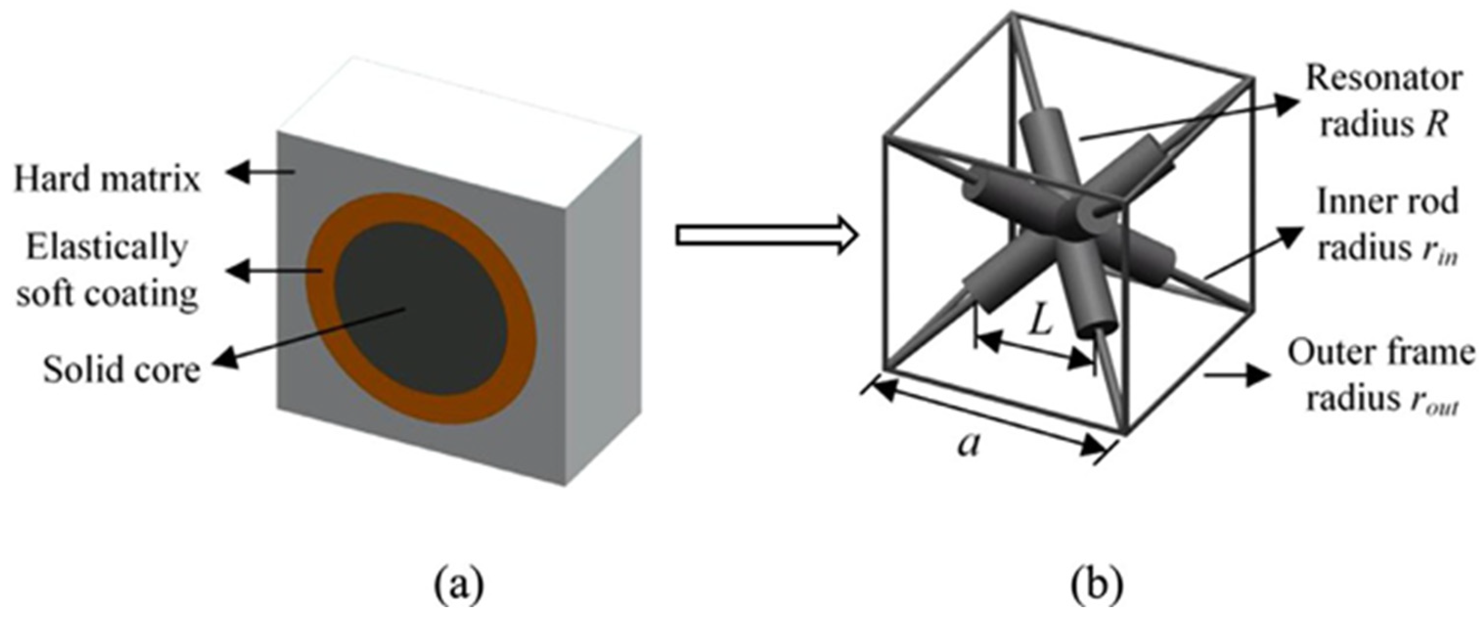
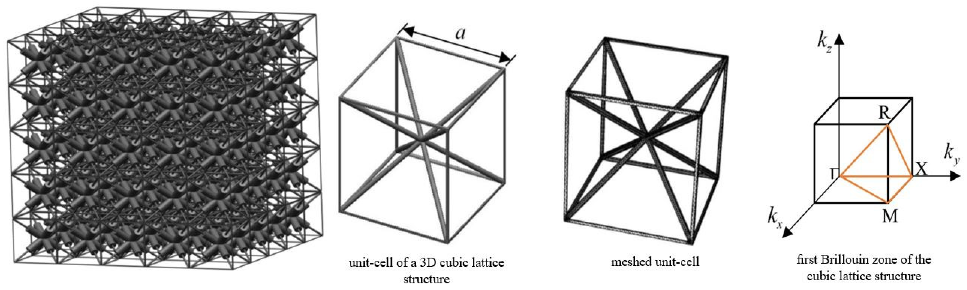
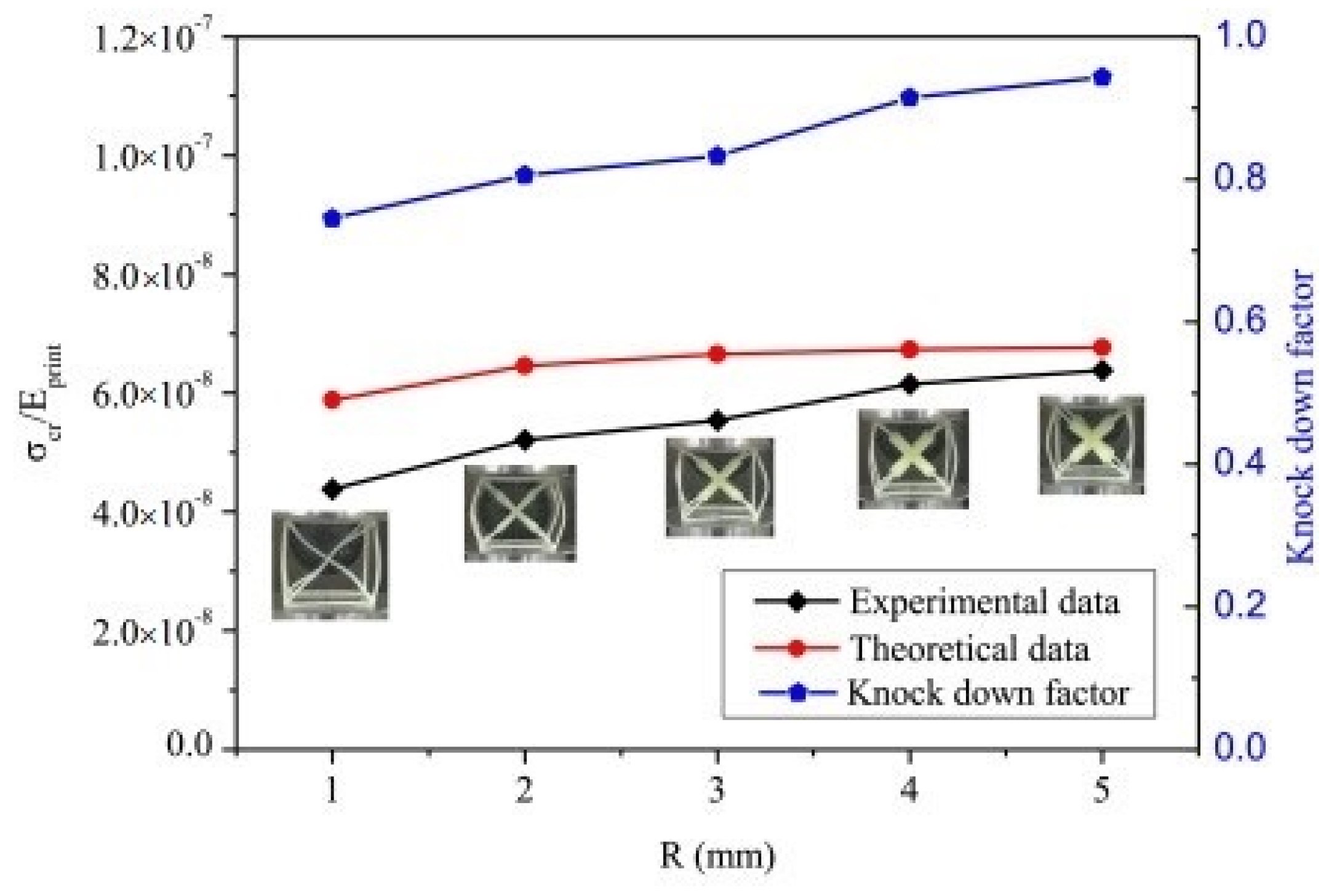
| artificial acoustic metamaterial | (3D) truss-lattice structures | bulk modulus, buckling strength, and stiffness-to-mass ratio | bulk modulus and buckling strength increase with radius, while stiffness decreases | [43] |
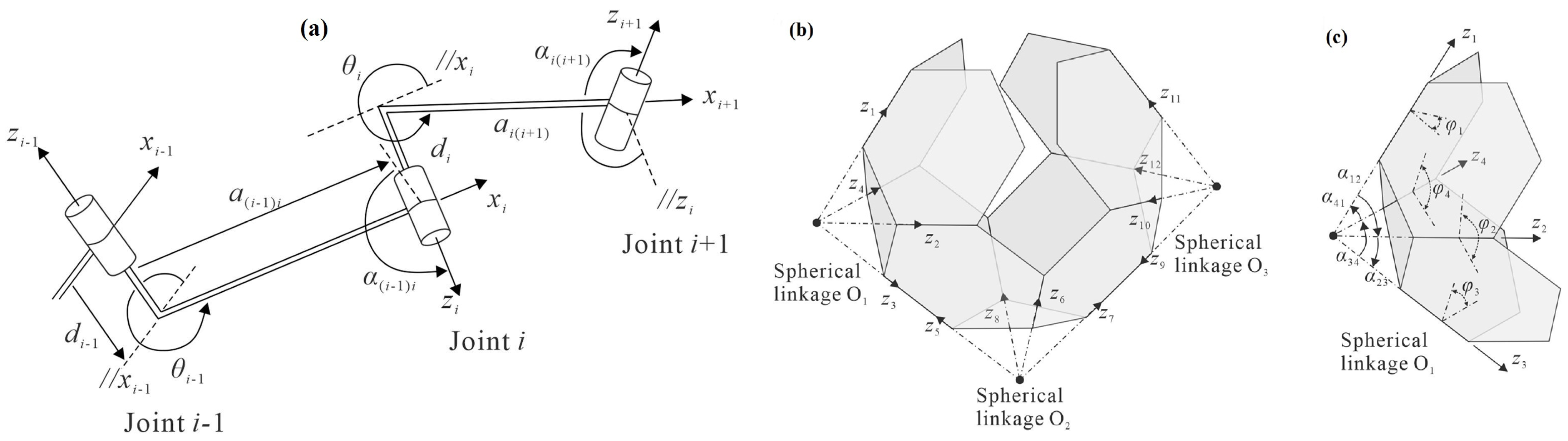
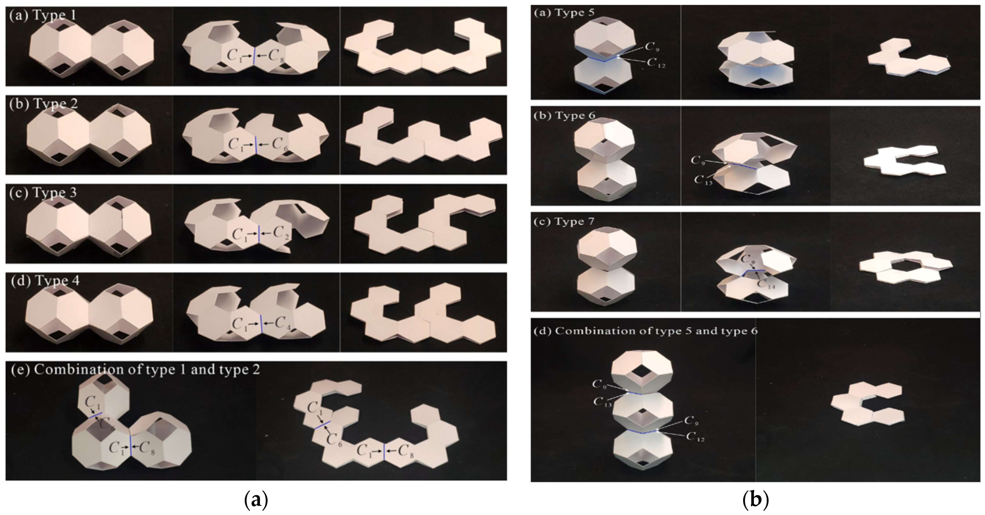
| 3D Archimedean solid flat using paper folding | origami and kirigami principles | geometrical parameters of spherical and Bennett linkages, dihedral angles | potential engineering applications of foldable cellular structures, such as space habitats and robot arms | [44] |
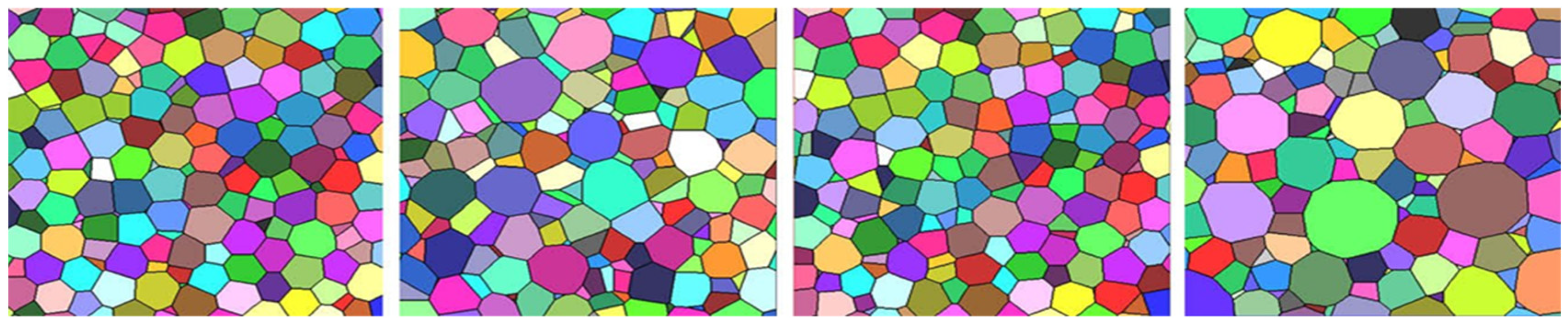
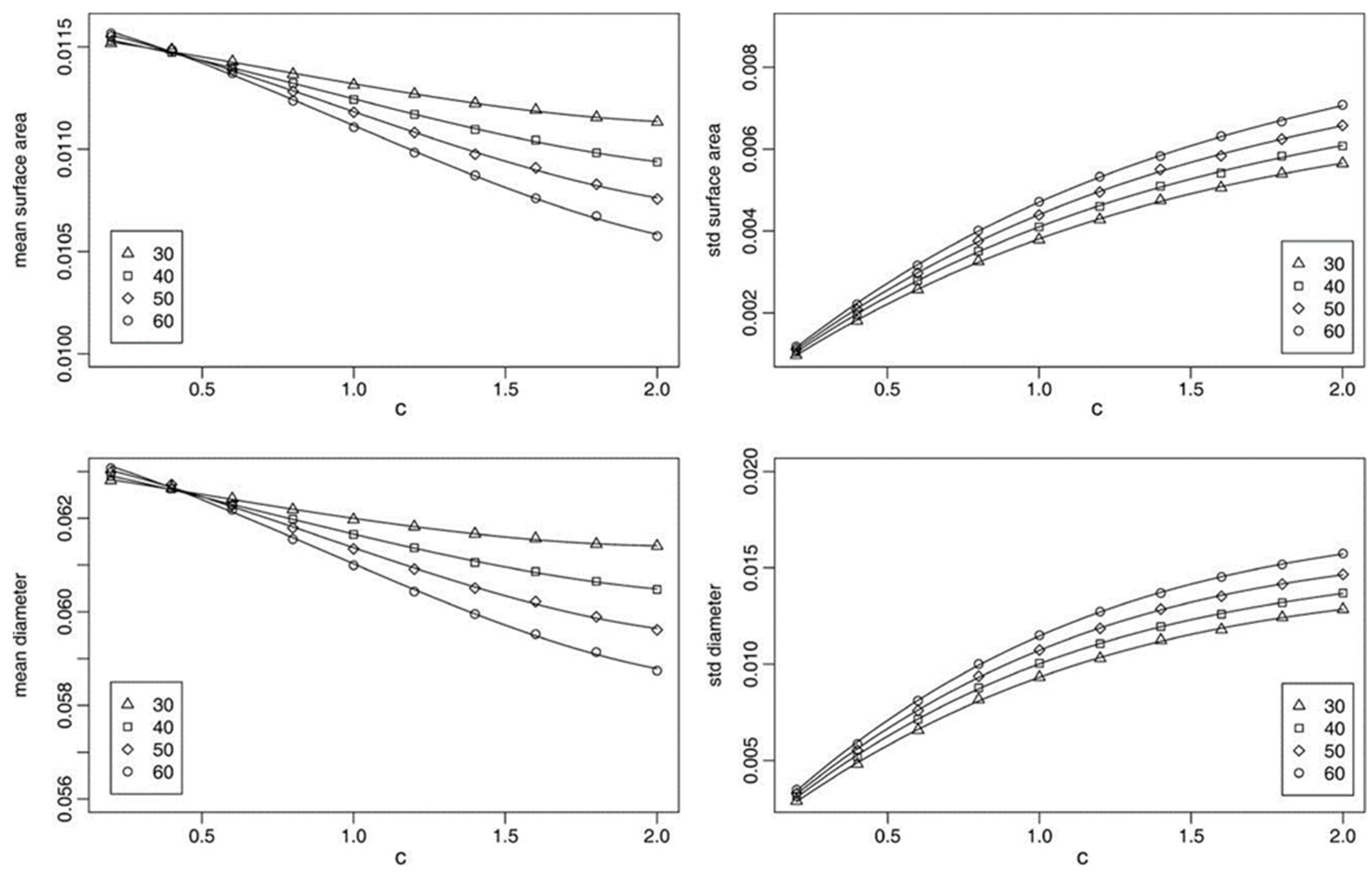
| polycrystalline materials | lognormal or gamma distributed volumes | volume, surface area, mean width and number of facets | difference between lognormal or gamma distributed tessellations | [46] |
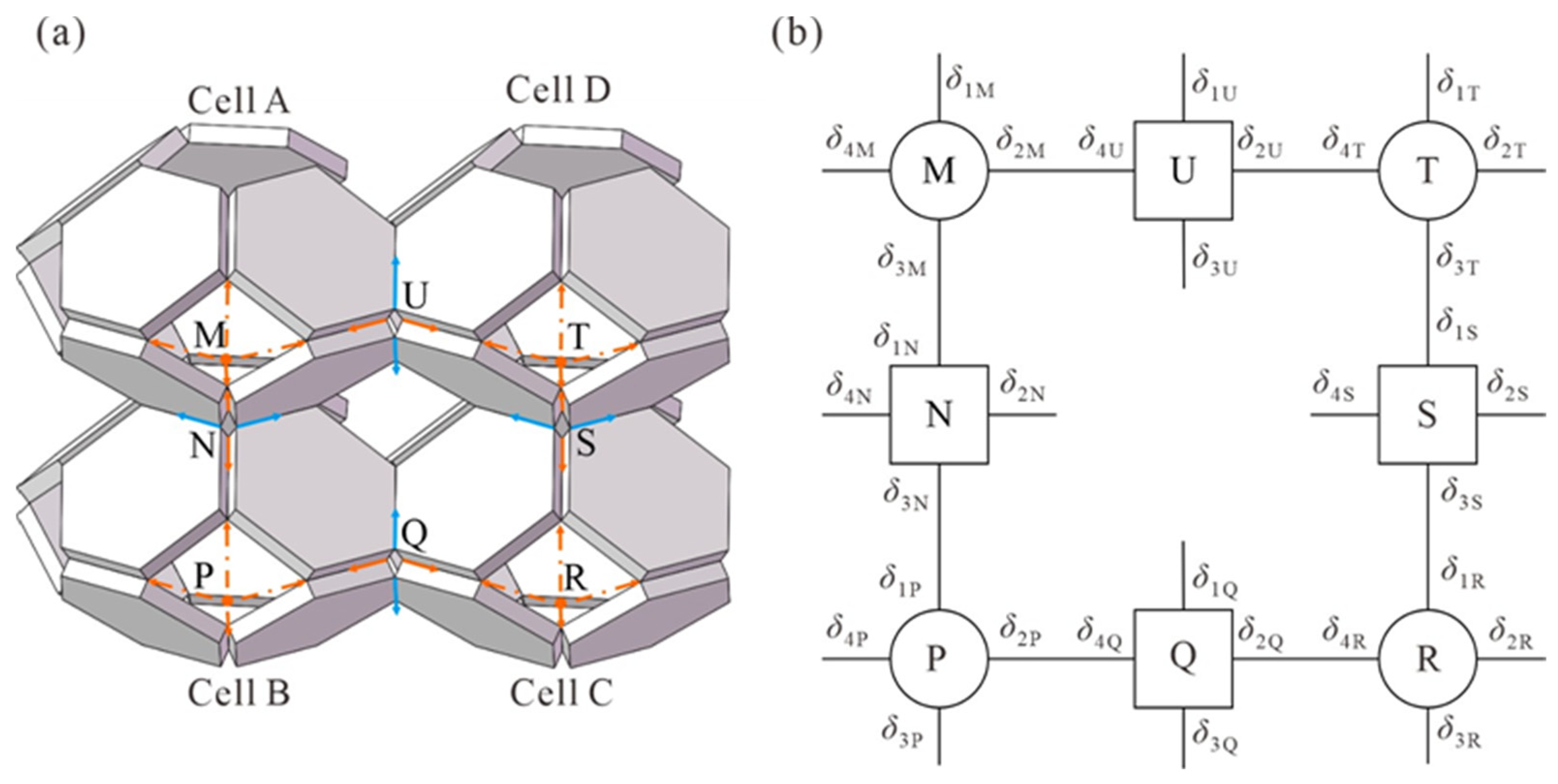
| - | hexagonal structure | strain localization and micro-buckling | microstructural instabilities and localization bands | [35] |
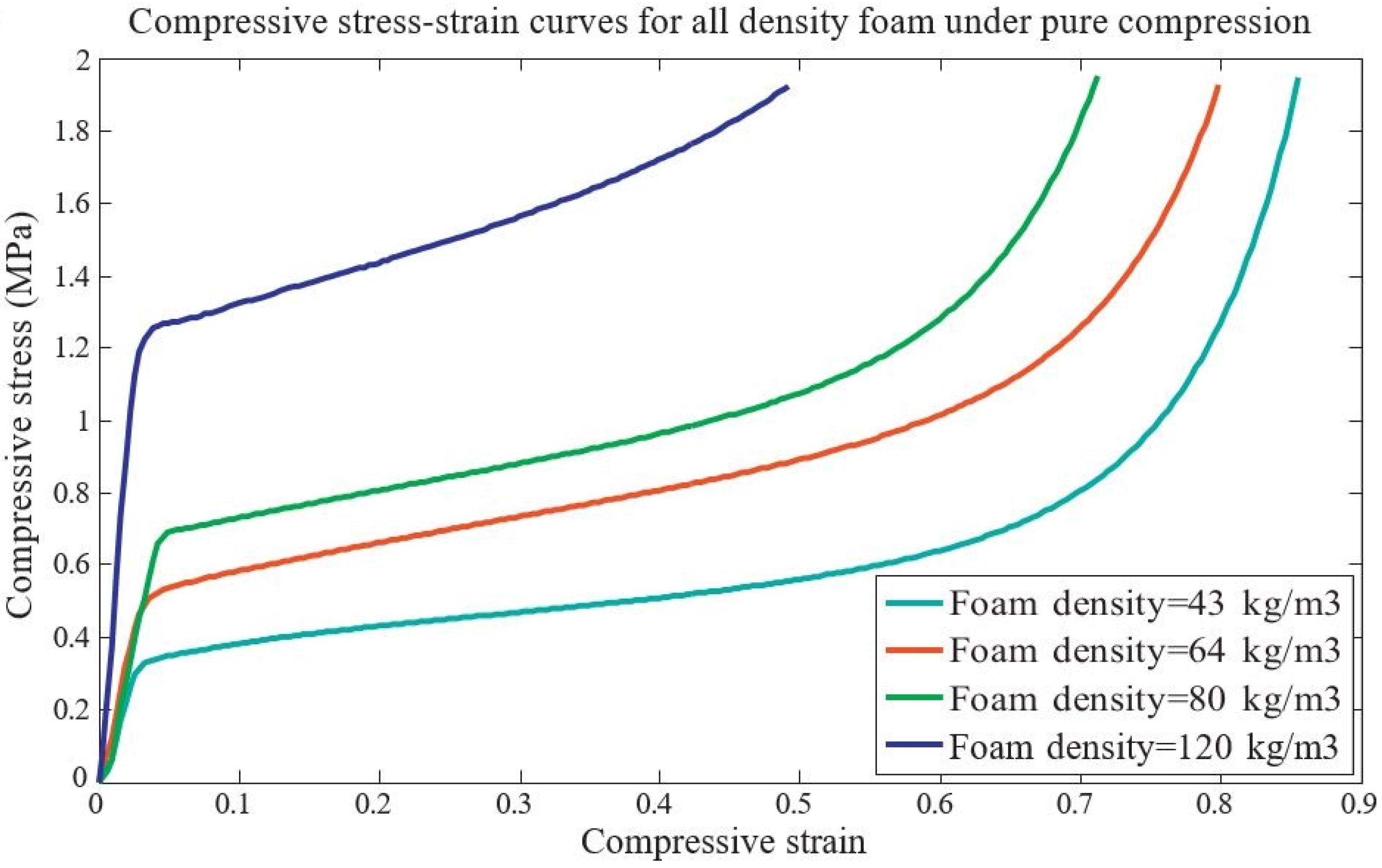
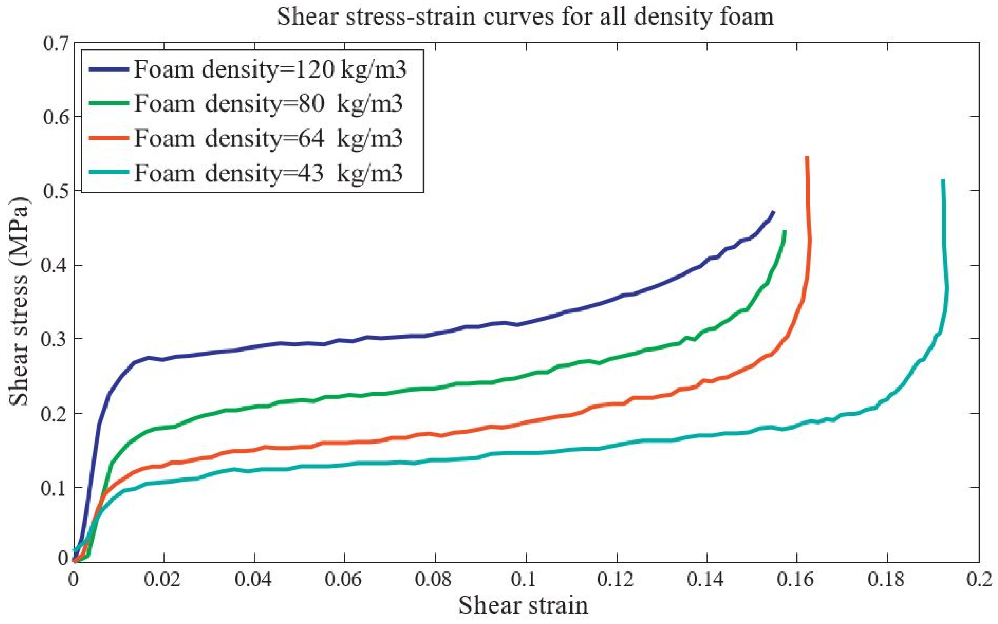
| polystyrene (EPS) foam | - | compressive and shear stresses | foam density and strain-rate | [47,48] |
| metal foams | 3D Voronoi structure | strain, stress ahead of the shock front, and dynamic stress–strain relationship | loading-rate sensitivity mechan, sm of cellular materials | [41] |
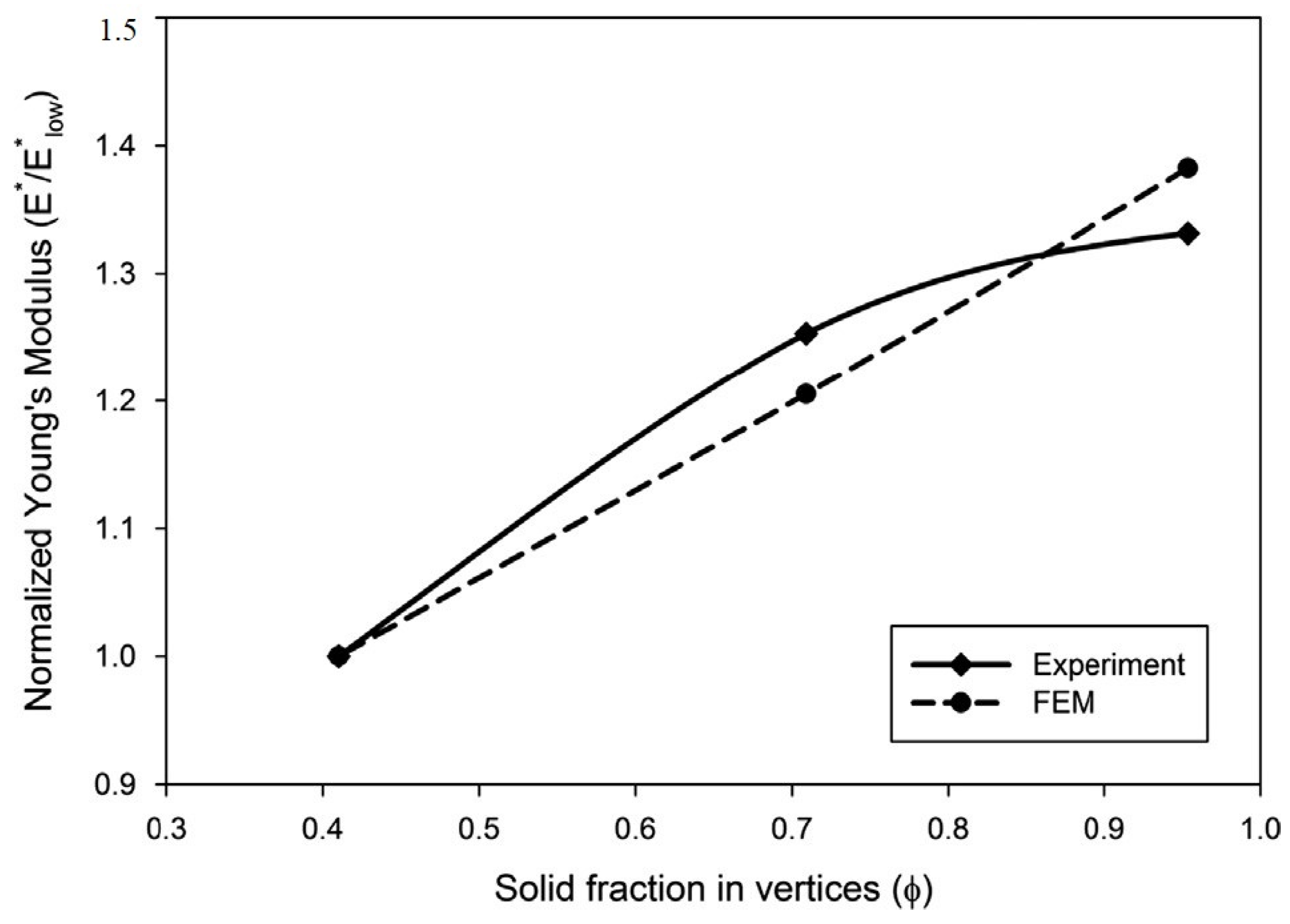
| photopolymer Objet Vero Blue Full Cure M840 material | open-cell structure | Young’s modulus and Poisson’s ratio | good agreement between numerical simulations and experimental results | [49] |
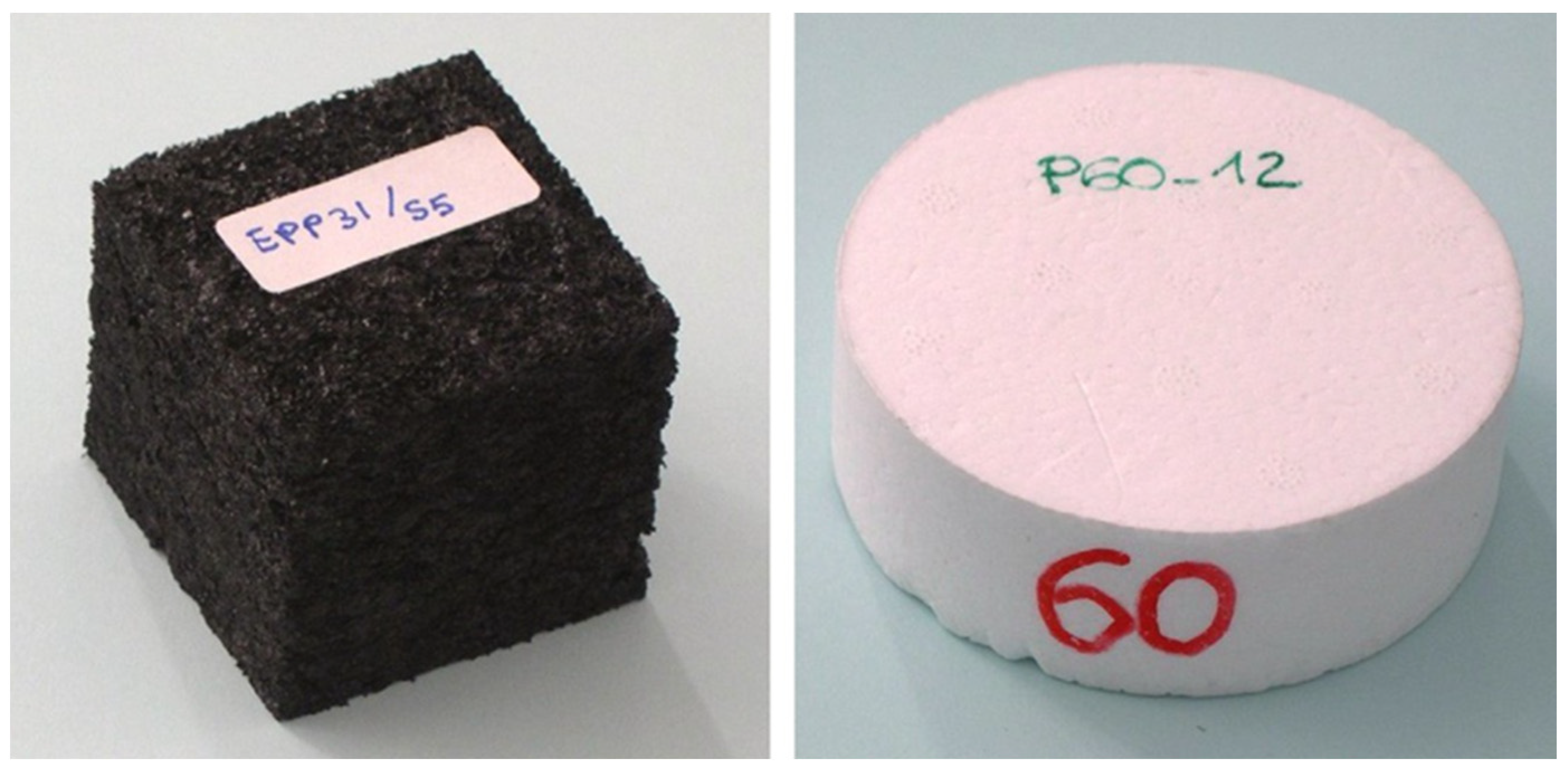
| various types of foams (EPP, PUR (Bayfill EA), EPS, and PPO/PS (Noryl GTX) | structural foams | Elastic property | introduces new empirical formulations and identifies density-dependent laws | [50] |
| - | hexagonal honeycomb structure | buckling behavior | establishes a homogenization theory and derived conditions for microscopic symmetric bifurcation | [34] |
| Polymethacrylimide (PMI) foam | 3D microstructures | strength–density, stress–strain curves, buckling strength index of cell walls, and deformation banding | deeper understanding of the mechanical behavior | [39] |
| Piezoelectrically active cellular solids | hexagonal, tetragonal, and triangular structure | elastic, dielectric, and piezoelectric properties | relationship between cellular structure, deformation modes, and electromechanical properties | [36] |
| Stochastic or Probability Method | Cellular Material | Improvement on Mechanical Property | Reference |
|---|---|---|---|
| Monte Carlo Simulation | Aluminum Foam | Compressive Strength | [57] |
| Monte Carlo Simulation (MCS)-based Stochastic Finite Element Analysis | Wood | Compression Strength | [58] |
| Hybrid Multilevel Approach based on Excitable Cellular Automata | Ceramic Coating—Polycrystalline Metallic Substrate | Deformation Processes | [42] |
| Lognormal Random Factor Accounting for Statistical Scatted | Aluminum Alloys (specifically 2024-T351) | Fatigue Crack Growth Rate | [59] |
| Monte Carlo Simulation (Poisson process) | Foam A | Compressive Strength | [60] |
| Finite Element Method with Random Fields | porous aluminum | tensile modulus and yield strength | [61] |
| Artificial Neural Networks for porosity prediction | wood fiber | elastic moduli | [62] |
| Utilized for modeling nano porous cellular materials using probability density functions | open-porous cellular materials | compressive response | [63] |
| Stochastic lattice creation techniques | cellular materials properties | heat exchangers and mechanical components | [64] |
| Stochastic tessellation via Aboav-Weaire law | classification and selection of cellular materials | biomimetic approach | [65] |
| Stochastic modeling based on μCT-image analysis | open-cell foam | microstructure complexity and mechanical performance | [66] |
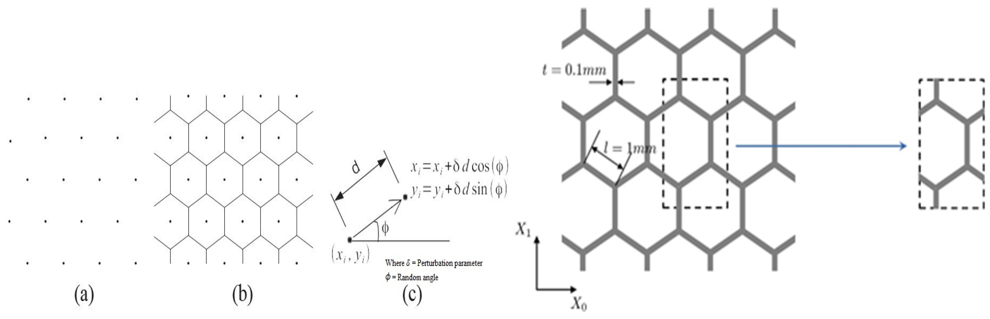
| Stochastic models | cellular materials imperfection (ti6al4v cellular structures) | mechanical property of 2d structure (elastic modulus and strength) | [67] |
| Finite element models | metal foams | dynamic stress–strain relationships and exploring energy absorption | [41] |
| lognormal distribution | Polymethacrylimide (PMI) foam | analytical constitutive model | [39] |
| Open Cell Foam | Close Cell Foam | Numerical Modeling | Difference in Mechanical Property | Reference |
|---|---|---|---|---|
| Interconnected porous structure | Closed gas-filled pores | Voronoi tessellation is used to model random polyhedral cells mimicking open-cell foam microstructure | Lower stiffness and strength compared to closed-cell foams | [68,69] |
| Open-cell foam has open, interconnected cells that absorb water and other substances. It is softer, lighter, and more flexible | Closed-cell foam has closed cells, which seal out water, air, and more. It is denser, more rigid, and more robust | Numerical modeling of open-cell metal foam with a Kelvin cell. Numerical and experimental study of open-cell foams for the characterization of heat exchangers | Open-cell foam is less dense and offers better sound absorption. Closed-cell foam is denser and offers higher strength and insulation. | [70,71,72,73,74] |
| Types of Cellular Material | Microstructure Formation Method | Reference |
|---|---|---|
| architected cellular materials | additive manufacturing | [85] |
| hard sphere packings with lognormal or gamma distributions | investigating geometric characteristics | [45] |
| cellular ceramic composites | 3d microarchitecture | [3] |
| - | cellular automata modeling for deformation processes | [86] |
| metals and alloys in laser additive manufacturing | laser additive manufacturing | [87] |
| porous metals | solid freeform fabrication techniques | [88] |
| - | neural cellular automata | [89] |
| hexagonal honeycomb cellular material | polynomial interpolation method | [35] |
| metal foams | 3D Voronoi structure | [41] |
| Poly-methacrylimide (PMI) foam | in situ x-ray micro-computed tomography (CT) | [39] |
| Types of Cellular Material | Microstructure Formation Method | Reference |
|---|---|---|
| Bio-Inspired Cellular Materials | Artificial Intelligence, Machine Learning, Deep Learning | [93] |
| Square Core Cellular Materials | Computational Homogenization | [94] |
| Cellular Metals | X-ray Computed Tomography, Infrared Thermography | [95] |
| High Entropy Alloys | Ab initio approaches | [96] |
| Closed-cell cellular materials | Finite shell elements modeling | [97] |
| Periodic cellular solids | Structural modeling | [98] |
| 3D printed cellular structures | Modeling and characterization | [99] |
| hexagonal honeycomb cellular material | arc-length path | [35] |
| metal foams | 3D Voronoi technique and discrete deformation gradient method | [41] |
| 3D open-cell structure | 3D CAD models | [49] |
| Poly-methacrylimide (PMI) foam | Digital volume correlation (DVC) | [39] |
| Displacement Rate [mm/min] | Es (ε = 0) [MPa] | σv [MPa] | σf [MPa] | εf |
|---|---|---|---|---|
| 0.4 | 1169.8 ± 158.7 | 27.4 ± 0.4 | 18.5 ± 0.6 | 0.3 ± 0.1 |
| 0.05 | 883.1 ± 166.4 | 19.9 ± 0.7 | 16.0 ± 0.5 | 0.4 ± 0.1 |
| Material System | l [mm] | h [mm] | t [mm] | b [mm] | θ [o] |
|---|---|---|---|---|---|
| H | 10.0 ± 0.1 | 10.0 ± 0.1 | 1.08 ± 0.3 | 10.0 ± 0.2 | 29.4 ± 1.7 |
| K | 10.0 ± 0.2 | - | 0.72 ± 0.1 | 10.0 ± 0.4 | 118.7 ± 3.7 |
| θ | E2* [MPa] | (σp)1* [MPa] | (σp)1* [MPa] | El2* [Pa.m4] | |
|---|---|---|---|---|---|
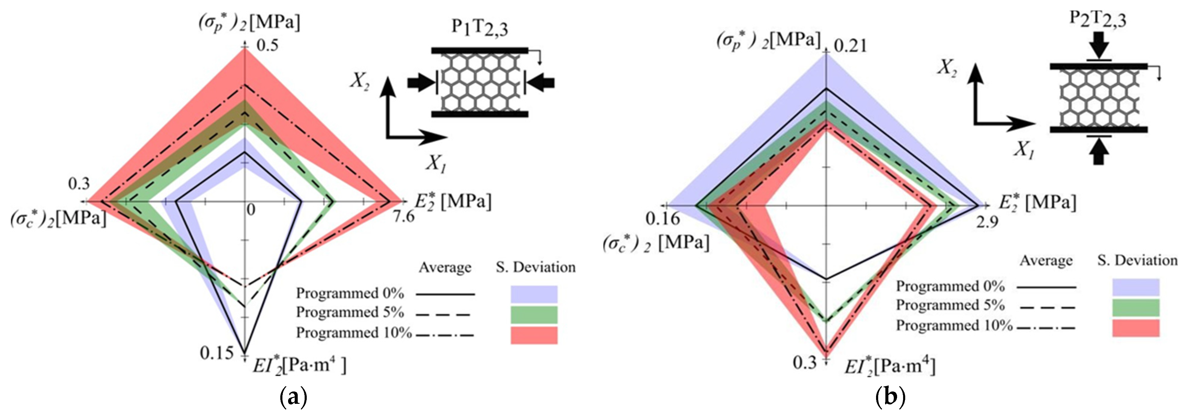
| Programmed 0% | 29.4 ± 1.7 | 2.7 ± 0.2 | 0.16 ± 0.05 | 0.13 ± 0.03 | 0.14 ± 1.98 × 10⁻³ |
| Programmed 5% | 35.1 ± 3.7 | 4.2 ± 0.1 | 0.29 ± 0.04 | 0.22 ± 0.04 | 9.97 × 10⁻² ± 2.45 × 10⁻⁴ |
| Programmed 10% | 38.3 ± 6.1 | 6.9 ± 0.6 | 0.38 ± 0.12 | 0.27 ± 0.03 | 8.08 × 10⁻² ± 1.35 × 10⁻⁴ |
| θ | E1* [MPa] | (σp)2* [MPa] | (σp)2* [MPa] | El2* [Pa.m4] | |
|---|---|---|---|---|---|
| Programmed 0% | 29.4 ± 1.8 | 2.7 ± 0.15 | 0.16 ± 0.05 | 0.13 ± 0.03 | 0.14 ± 1.98 × 10⁻³ |
| Programmed 5% | 27.1 ± 2.7 | 2.3 ± 0.11 | 0.13 ± 0.01 | 0.11 ± 0.02 | 0.23 ± 0.01 |
| Programmed 10% | 21.4 ± 7.4 | 1.9 ± 0.13 | 0.11 ± 0.01 | 0.09 ± 0.03 | 0.29 ± 0.01 |
| Programming Cycle | E2* [MPa] | E2* [MPa] Direct Programing Cycle |
|---|---|---|
| 0 | 2.7 | 2.7 ± 0.5 |
| 1 | 4.1 | 4.2 ± 0.8 |
| 2 | 2.6 | 2.7 ± 0.5 |
| 3 | 6.4 | 6.9 ± 0.3 |
| 4 | 2.5 | 2.7 ± 0.5 |
| θ | E2* [MPa] | (σp)2* [MPa] | (σp)2* [MPa] | El2* [Pa.m4] | |
|---|---|---|---|---|---|
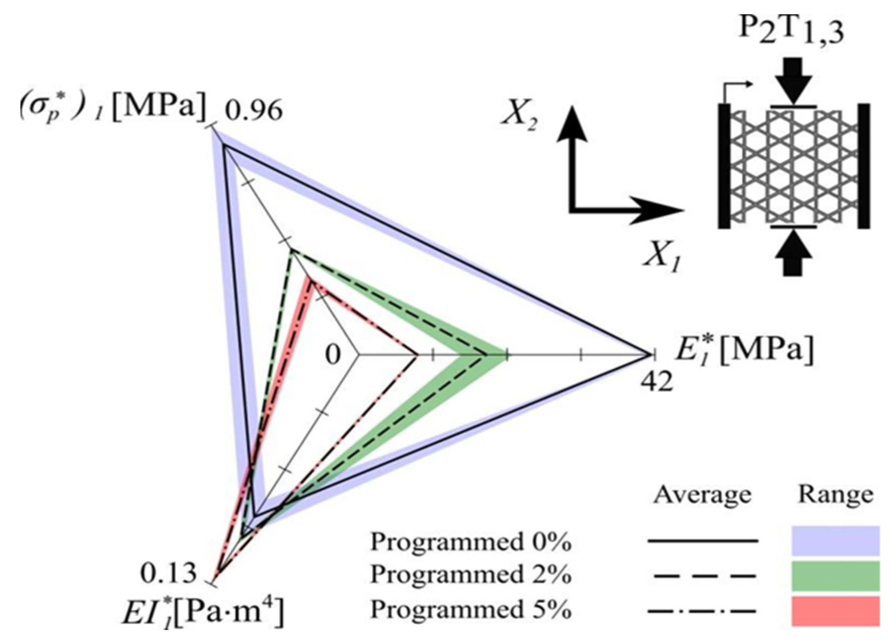
| Programmed 0% | 118.7 ± 3.8 | 41.1 ± 0.45 | 0.88 ± 0.06 | −− | 9.33 × 10⁻² ± 7.6 × 10⁻³ |
| Programmed 2% | 107.5 ± 6.9 | 17.9 ± 0.03 | 0.44 ± 0.01 | 0.26 ± 0.06 | 0.10 ± 2.5 × 10⁻³ |
| Programmed 5% | 92.3 ± 10.2 | 8.3 ± 0.18 | 0.31 ± 0.02 | 0.28 ± 0.02 | 0.13 ± 3.7 × 10⁻³ |
| Programming Cycle | E1* [MPa] | E1* [MPa] Direct Programing Cycle |
|---|---|---|
| 0 | 41.1 | 41.1 ± 0.45 |
| 1 | 17.6 | 17.8 ± 0.03 |
| 2 | 39.1 | 41.1 ± 0.45 |
| 3 | 7.9 | 8.3 ± 0.18 |
| 4 | 36.4 | 41.1 ± 0.45 |
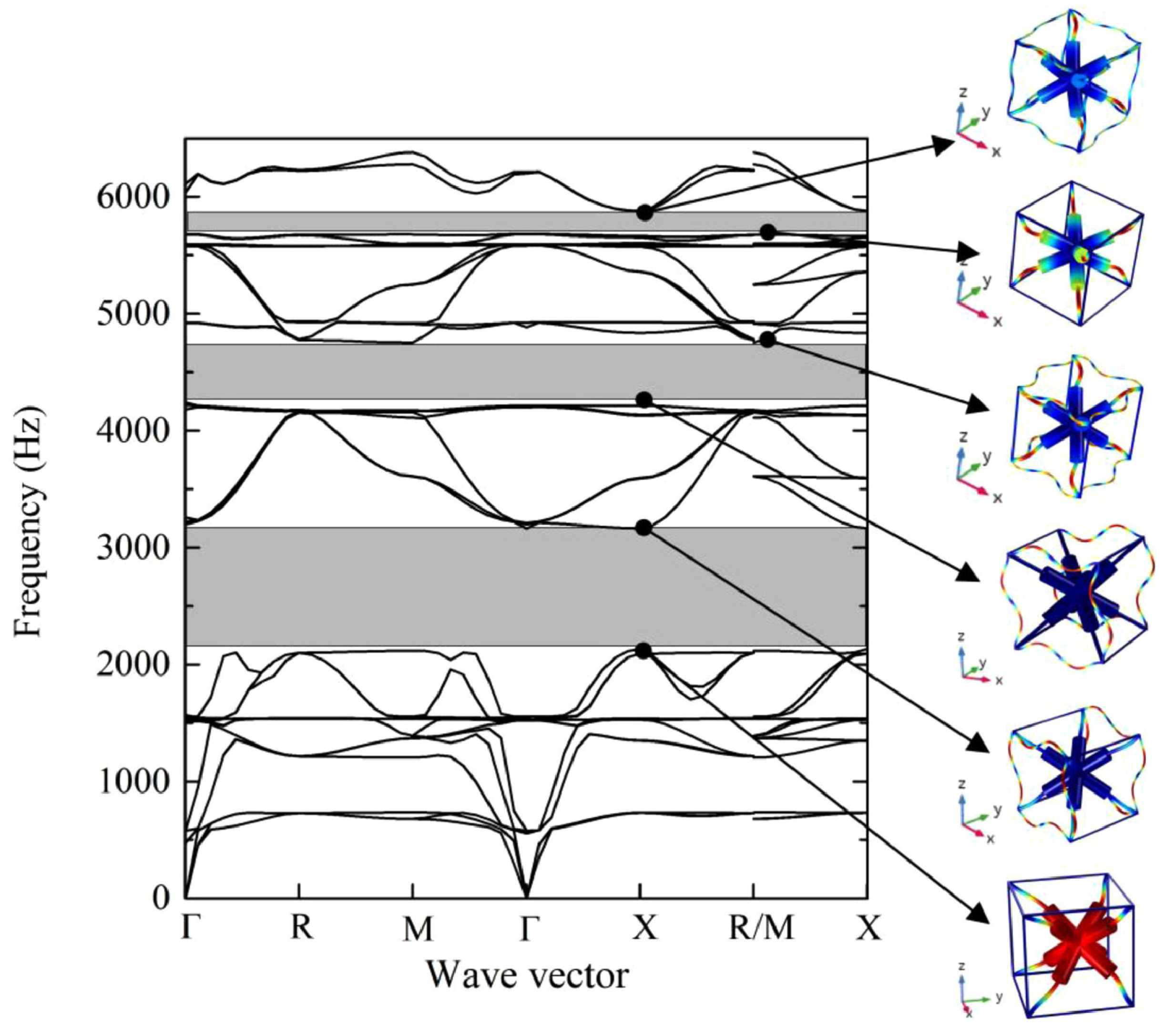
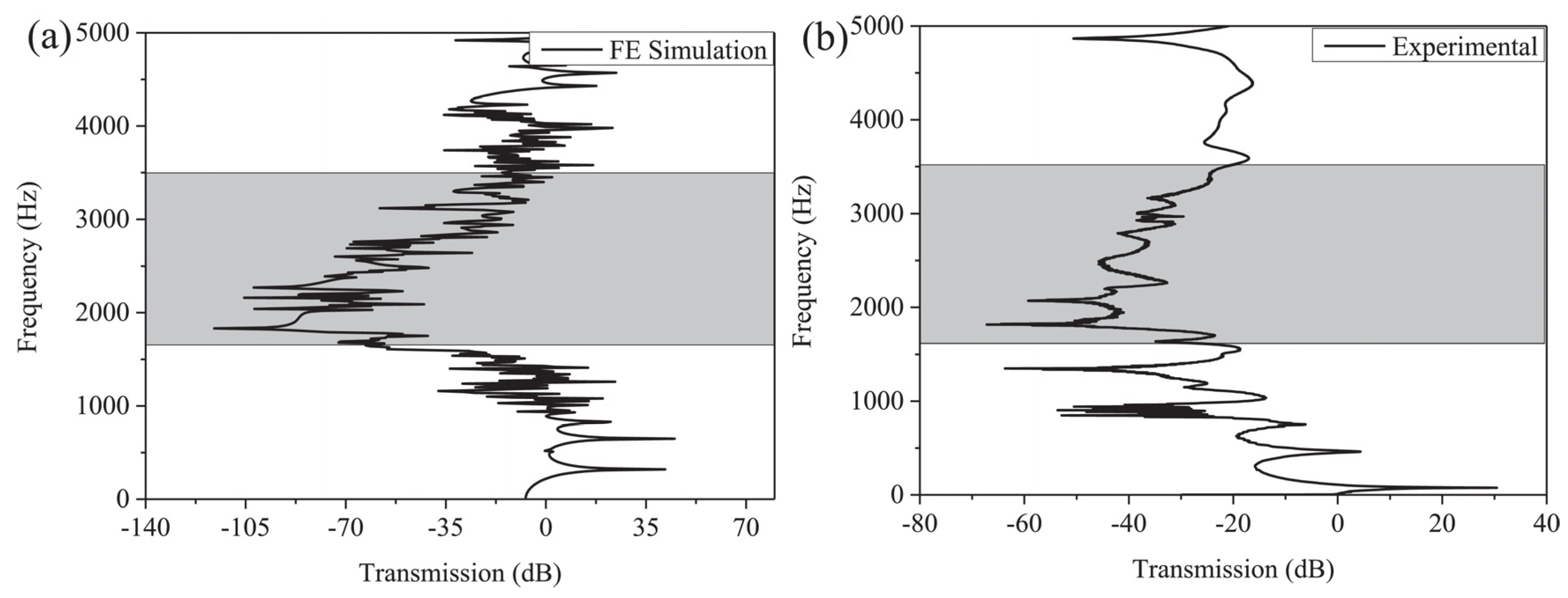
| Unit Cell L (cm) |  |  |  |  |  |  |
| Bandgap (Hz) | 2648–3154 | 1860–2291 3254–3504 | 1723–2608 | 1719–2800 | 4572–4864 | 1723–2020 2224–2317 8–2580 |
| Computer Simulation Technique | Uncertainty Threshold | Reference |
|---|---|---|
| Cellular automata simulations of microstructure evolution | Uncertainty quantification in multiscale material modeling | [129] |
| Finite Element Analysis (FEA) | Investigates the impact of functionally graded porosity on the energy absorption of metal lattices. | [130] |
| Coupled FEA and Discrete Element Method (DEM) | Develops a multiscale modeling framework to predict the mechanical response of polymer cellular solids under impact. | [40] |
| Thresholding segmentation | Thresholding can be used to reduce segmentation errors and uncertainty in material imaging, especially when high contrast is present. Proper selection of threshold values is important. Heterogeneous thresholding may be needed for cellular materials with complex microstructures. | [131] |
| A multiscale optimization framework considering microscale material uncertainties | Designs optimized assuming spatially varying material uncertainties are up to 74% more robust (in terms of standard deviation of compliance) compared to designs optimized with uniform uncertainties when subjected to spatially varying uncertainties. | [132] |
| Ensemble methods for molecular dynamics simulations | Ensemble methods play a key role in uncertainty quantification for molecular dynamics simulations of materials. Using 25 replicas with 4 ns of simulation each can often achieve accurate and reproducible results. | [133] |
| Probabilistic cellular automata simulations, Metamodeling | Quantitative assessment of uncertainties is essential. Advanced statistical methodology is needed for uncertainty propagation and sensitivity analysis. | [134] |
| Generative Adversarial Networks (GANs) | Utilizes machine learning to optimize the design of cellular materials for bone implant applications | [135] |
| Finite Difference Time Domain (FDTD) method | Investigates bioinspired cellular designs for manipulating sound waves | [136] |
Disclaimer/Publisher’s Note: The statements, opinions and data contained in all publications are solely those of the individual author(s) and contributor(s) and not of MDPI and/or the editor(s). MDPI and/or the editor(s) disclaim responsibility for any injury to people or property resulting from any ideas, methods, instructions or products referred to in the content. |
© 2024 by the authors. Licensee MDPI, Basel, Switzerland. This article is an open access article distributed under the terms and conditions of the Creative Commons Attribution (CC BY) license (https://creativecommons.org/licenses/by/4.0/).
Share and Cite
Iqbal, S.; Kamiński, M. Review Study on Mechanical Properties of Cellular Materials. Materials 2024, 17, 2682. https://doi.org/10.3390/ma17112682
Iqbal S, Kamiński M. Review Study on Mechanical Properties of Cellular Materials. Materials. 2024; 17(11):2682. https://doi.org/10.3390/ma17112682
Chicago/Turabian StyleIqbal, Safdar, and Marcin Kamiński. 2024. "Review Study on Mechanical Properties of Cellular Materials" Materials 17, no. 11: 2682. https://doi.org/10.3390/ma17112682
APA StyleIqbal, S., & Kamiński, M. (2024). Review Study on Mechanical Properties of Cellular Materials. Materials, 17(11), 2682. https://doi.org/10.3390/ma17112682