Abstract
Multiple thick film samples of the solid solution were prepared using physical vapour deposition over a borosilicate glass substrate. This synthesis technique allows continuous variation in stoichiometry, while the distribution of silver or palladium atoms retains the arrangement into an on-average periodic lattice with smoothly varying unit cell parameters. The alloy concentration and geometry were measured over a set of sample points, respectively, via energy-dispersive X-ray spectroscopy and via X-ray diffraction. These results are compared with ab initio total energy and electronic structure calculations based on density functional theory, and using the coherent potential approximation for an effective medium description of disorder. The theoretically acquired lattice parameters appear in qualitative agreement with the measured trends. The numerical study of the Fermi surface also shows a variation in its topological features, which follow the change in silver concentration. These were related to the electrical resistivity of the alloy. The theoretically obtained variation exhibits a significant correlation with nonlinear changes in the resistivity as a function of composition. This combined experimental and theoretical study suggests the possibility of using resistivity measurements along concentration gradients as a way to gain some microscopic insight into the electronic structure of an alloy.
1. Introduction
Silver (Ag) and palladium (Pd) are both noble metals with a relatively high electrochemical potential, i.e., they are not readily reacting with oxygen or water. Silver is used as a unique material with its selectivity to ethylene in the selective partial oxidation to yield ethylene oxide [1]. Other applications rely on the oligodynamic effect in which very small amounts of silver ions are released that have a strong impact on microorganisms. This is why thin silver fibers in cotton are used to improve the wound healing in medical applications; they can also hinder bacteria from digesting sweat in socks resulting in olfactoric challenges. Palladium also has a lot of applications as a catalyst. While homogeneous catalytic use, e.g., for cross-coupling, is important in synthetic chemistry, it is, in particular, its use in heterogeneous catalysts such as the three-way catalytic converter, the Lindlar catalyst, that makes this element so important. It shows a unique affinity to hydrogen and acts as a hydrogen-permeable membrane at higher temperatures. This effect can be used to purify hydrogen-containing gases. The combination of these two properties make Pd the element of choice for hydration and dehydration reactions.
While the importance of each of the elements alone is already impressive, it must be emphasized that the possibility to form binary alloys over a wide range of compositions allows the properties to be tuned to the actual needs. Silver reacts easily with H2S and forms highly insoluble AgS as a black coverage. This tarnishing can be suppressed when alloying Ag with Pd [2].
The electronic structure of Ag-Pd catalysts and electrocatalysts is highly important as they are used for a large range of reactions, namely improved ethylene epoxidation [3], reductive homocoupling of alkyl bromides [4], selective reductive homocoupling of alkyl iodides [5], electrocatalytic de-/hydrogenation [6] or dichlorination of dichlorophenoxyacetic acid [7], the direct synthesis of hydrogen peroxide [8] and ultrastable reduction to formate [9].
Besides the direct metallurgical alloying, Ag-Pd alloys can also be prepared through electroless plating [10], e.g., against biofouling [11], or through DC sputtering, e.g., as a lubricant in high-temperature applications [12]. Thin films of Ag-Pd can be used to improve the SERS activity [13] or to prepare flexible electrically conductive fibers [14].
The affinity to hydrogen can be used not only in the above-mentioned catalytic reaction but also for hydrogen sensing [15]. On the other hand, the adsorption can already change the Ag-Pd thin film surface through segregation depending on the composition [16]. Ag-Pd films are hydrogen permeable but the permeability depends on the alloy’s composition and structure [17], and the structure may change upon loading and discharging [18]. Theoretical work supports the experimental findings that a non-ideal absorption effect occurs at temperatures below 300 °C [19]. Experimental support can be found from NMR measurements, which showed more than one possible jump process [20]. Of high practical interest is the fact that the three hydrogen isotopes H, D and T show different permeation rates [21], which is considered for the treatment of water containing tritium, e.g., from the Fukushima nuclear power plant [22]. Given the importance of Ag-Pd membranes for applications at higher temperatures, a number of investigations have been performed to show how Ag-Pd alloys behave upon heating [23] and their thermal stability [24].
Variations in the composition and stoichiometry of metallic alloys allow the optimization of materials’ properties for a variety of applications. The experimental study of impurities, defects and material properties in disordered systems and their theoretical description is a fundamental part of material science. At a microscopic level, these features are mainly determined by the electronic structure. The density of states (DOS), the electronic band structure and the shape and topology of the Fermi surface provide, in particular, very useful parameters to understand how certain macroscopic features emerge, and can potentially be tuned in the desired directions.
Variations in the composition and stoichiometry of metallic alloys allow to optimize materials properties for a variety of applications. The experimental study of impurities, defects and material properties in disordered systems and their theoretical description are a fundamental part of material science. At a microscopic level, these features are mainly determined by the electronic structure. The density of states (DOS), the electronic band structure and the shape and topology of the Fermi surface provide in particular very useful parameters to understand how certain macroscopic features emerge, and can potentially be tuned in the desired directions.
Previous studies [25] have introduced the idea that electronic topological transitions (ETTs), i.e., the variations in the shape and connectivity of the Fermi surface, play an important role in controlling the bulk modulus and other mechanical properties of a metal. ETTs can be caused by doping of pure metals. In addition, transport properties such as the electrical resistivity undergo significant changes. While applied pressure and in situ/operando spectroscopy can provide ways to, respectively, sweep through and characterize these ETTs within a single sample, the tuning of stoichiometry offers a permanent route to the engineering of the desired features in an alloy, or conversely, to infer from simple conductivity measurements other features of interest which also originate from the same microscopic physics.
An ideal scenario for the cross-validation of this type of investigation is offered by metallic solid solutions such as , where the constituents remain highly miscible over a continuum of concentration values. Earlier numerical studies [26,27,28,29] highlighted the connection between the topology of the Fermi surface and the properties of an alloy, such as the bulk modulus. Following on from those studies, we propose here a systematic comparison between experiments and ab initio theoretical descriptions, which aims to carefully validate the connection between subtle features of the alloy’s electronic structure and its measured lattice parameters and the literature values of the resistivity.
In our study, we combine experiments and theory in the following way. First, alloys were fabricated using vapor deposition, and then the structure and stoichiometry of the alloys were studied with energy-dispersive X-ray spectroscopy and with X-ray diffraction. The obtained results were compared with first-principles calculations for total energy and structure. Further, the electronic structure and transport properties were studied from first principles and compared with experiments reported in early studies.
Various samples of the solid solution have been prepared by means of physical vapor deposition (PVD) [30] over a borosilicate glass substrate in order to obtain a continuous lateral concentration gradient between pure silver and pure palladium. The resulting alloy thin films have been characterized by measuring local thickness and the corresponding stoichiometry and crystalline lattice parameters, respectively, through energy-dispersive X-ray spectroscopy (EDX) and through X-ray diffraction (XRD). On the numerical side, we adopted the effective medium description offered by the coherent potential approximation (CPA) [31] in combination with density functional theory (DFT), implemented within a self-consistent Korringa–Kohn–Rostoker (KKR) Green’s function framework.
Comparing experimentally and theoretically obtained structural properties, we conclude that our first-principles approach can adequately describe the ground state properties of alloys. Further electronic and transport properties of the alloys were studied from first principles and the results were compared with previous experiments.
This combined study allows the experimental values of the resistivity to be related to ETTs that manifest as changes in the shape and connectivity of the electronic Bloch spectral function (BSF) at the Fermi level [32]. In particular, we improve our earlier study of these effects [29] by taking into account here the relativistic effects by numerically solving the Kohn–Sham problem in terms of the Dirac equation [33]. Previous ab initio results based on the scalar relativistic (SR) approximation [34] could show the relationship between some ETT features and changes in the calculated bulk modulus. Here, it is shown how the fully relativistic (FR) approach produces a more accurate and realistic band structure in comparison with experimental results. The importance of fully relativistic effects appears, in particular, in the Pd-rich region of the Ag-Pd solid solution, where FR calculations of the Fermi surface show, for instance, a neck around the L point of the Brillouin zone which is not visible at the SR level. Furthermore, FR calculations allow the degeneracy in the electronic pocket around the X point to be resolved (see Figure 2 in Ref. [28]).
This paper is structured as follows. The experimental results are first presented in Section 2. The outcomes of SR and FR ab initio calculations, highlighting in particular the role of ETTs as a function of Ag concentration, are then examined in Section 3. Section 4, at the end, proposes a summary of the main findings and our conclusions from the study.
2. Samples’ Preparation and Characterization
PVD in the form of thermal co-evaporation was performed over a borosilicate glass substrate in order to prepare thick films of with a continuous change in concentration along one dimension of the glass strip, which serves as a substrate [30]. This sample preparation technique allows us to maintain at all intermediate concentrations the reference fcc unit cell structure common for both pure Ag or pure Pd. Alternative growth methods, such as sputtering or even electron-beam vaporization, would instead result in amorphous alloy phases [35] unsuitable for the present studies. Three distinct samples were produced and characterized, each spanning an interval of Ag concentrations chosen in partial overlap with the other ones in order to allow cross-validation of the results. In each case, the film thickness, its stoichiometry and its fcc lattice parameter were measured at multiple points, i.e., over a range of concentrations between pure Pd and pure Ag extremes. Each aspect of this procedure is outlined in further detail in the following.
2.1. Sample Growth via Physical Vapour Co-Deposition (PVD)
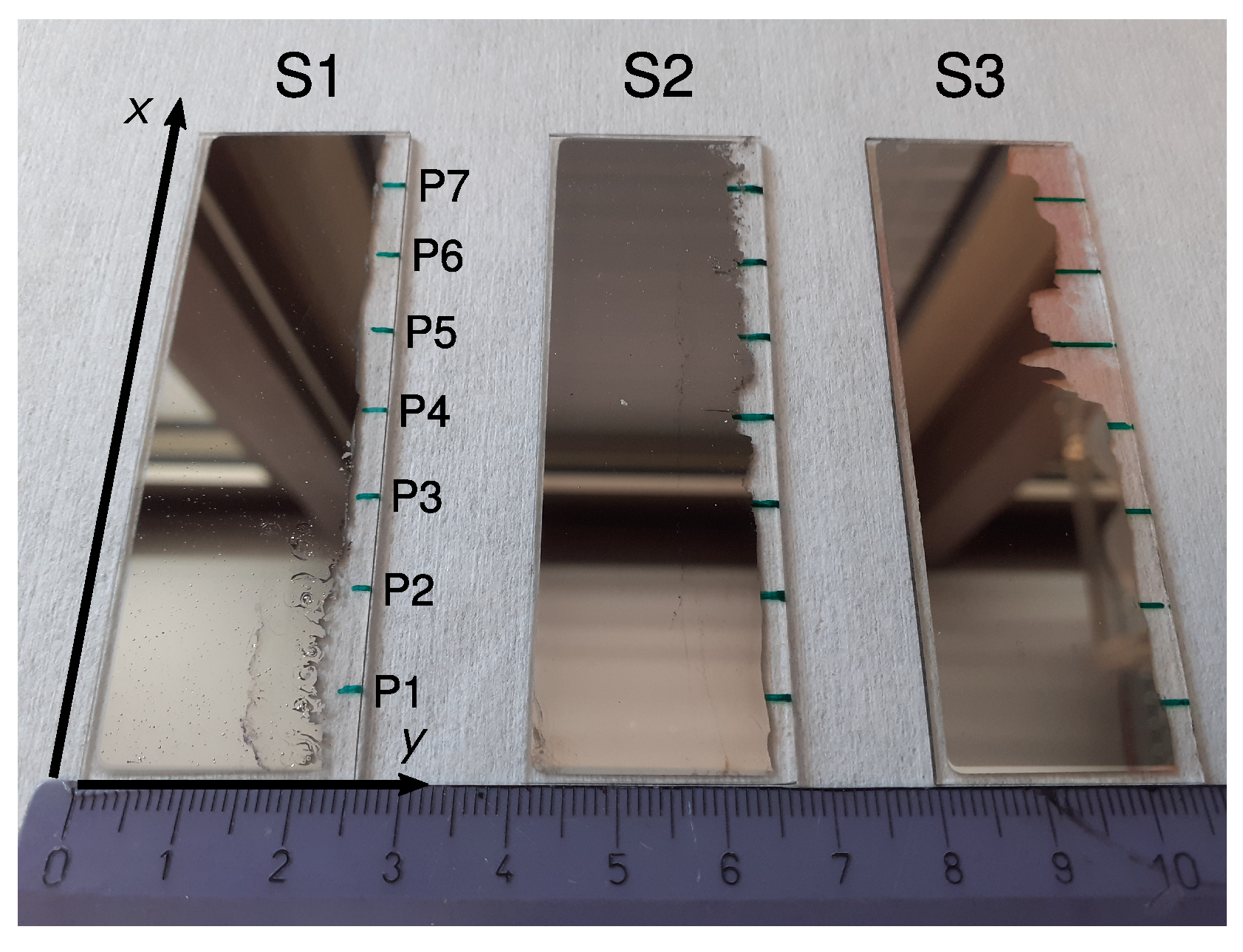
Ag and Pd were deposited on top of three microscope slides of borosilicate glass with dimensions 76 mm × 26 mm × 1 mm. These are referred to as the samples S1, S2 and S3 in the following. This growth results in a smoothly varying atomic concentration between 0 and 1 along the x direction, aiming for an intermediate Ag concentration (middle point in Figure 1) of about 10 at.% for sample S1, 50 at.% for sample S2 and 90 at.% for sample S3. The end and start points of S1, S2 and S3 were prepared with some overlap in concentration along x for cross-validation purposes across samples.
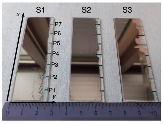
Figure 1.
Photograph of samples S1, S2 and S3. On the blank edges (right), the measurement points (labeled P1–P7 in S1) were marked as green lines on the backside of the glass plates. A ruler with marks every centimeter is shown at the bottom for scale. Reddish regions in sample S3 stem from silver salts caused by a reaction with the glass plate. These do not affect further measurements however.
The deposition was performed by placing pure metallic Ag and Pd in a boron nitride crucible and by thermally evaporating inside the Thermal Co-Evaporation Chamber (THEO) within the CALMAR cluster [36]. The deposition rates of Ag and Pd are listed in Table 1, together with the initial and final pressures during the de position. The completed Ag-Pd libraries are shown in Figure 1.

Table 1.
Deposition rates of Ag () and Pd () for the samples S1, S2 and S3 used during PVD. The base pressure was and did not increase above during the deposition.
The samples S1 and S2 exhibit defects in the form of shrinkholes. They occur with a higher density at the surface in regions with a high Pd concentration. This is a consequence of the higher melting point of palladium and is in agreement with Grüneisen’s rule [37]. When the temperature is lowered, Pd tends to solidify before Ag. This leads to the contraction of its occupied volume, resulting in local distortions of the lattice and, in particular, the formation of holes at the surface.
After the evaporation, an EDX (Section 2.3) was performed to map the concentration along the samples. The Ag-Pd layer was then partially removed as shown on the right edges of the samples in Figure 1 and seven spots P1–P7 at 1 cm intervals along the x side (green marks in Figure 1) were chosen for the characterization steps detailed in Section 2.2 and Section 2.4 below.
2.2. Film Thickness
We assessed whether the samples can be considered as bulk-like by first measuring the thickness of each film using contact profilometry at the measurement points P1–P7 along the x side of the samples (Table 2).
Table 2.
Thickness of the film for the samples S1, S2 and S3 measured at the points P1–P7 (see Figure 1).
The larger differences in the Ag-Pd layer thickness for the samples S1 and S3 are due to the geometry of the PVD setup and to the different deposition rates required to achieve the desired stoichiometry (see Section 2.1). The variable thickness along the x side of each strip is plotted in Figure 2. A cubic B-spline is shown as a continuous black line along with the data to highlight the trend. Overall, the thickness of the AgPd films is confirmed to be larger than 120 nm throughout all samples. This corresponds to approximately 300 atomic layers, allowing a bulk-like description of the material to be adopted in the theoretical study of Section 3.
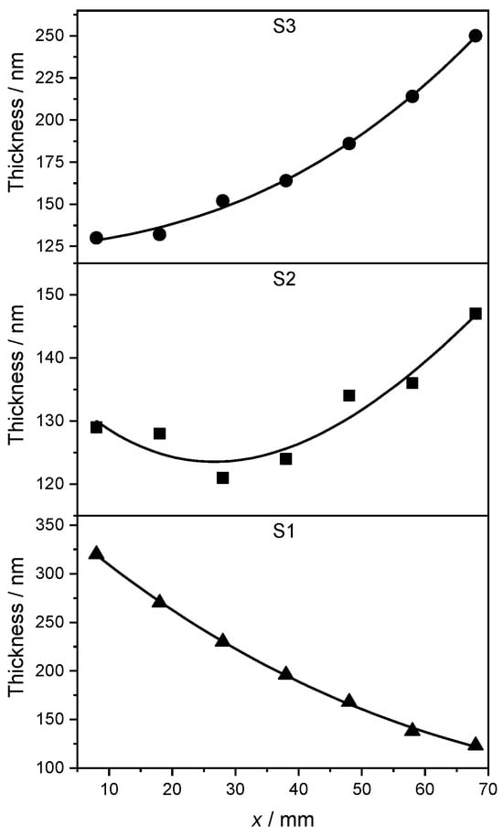
Figure 2.
Thickness of the Ag-Pd films as a function of position along the x direction. At x = 8 cm (measurement point P1) in S1 and at x = 68 cm (measurement point P7) in S3, the composition was, respectively, pure Pd and almost pure Ag, see Table 3. The concentration in S2 along the x direction varies according to Table 3, too. A cubic B-spline is shown as continuous black line to show the trend.
2.3. Stoichiometry via Energy-Dispersive X-ray Diffraction (EDX)
The Ag concentration of each sample was determined as a function of position along the strip by means of EDX mapping [36]. This technique was favored over more surface sensitive methods, like Auger electron spectroscopy (AES), since the composition at the surface is likely to not be representative of the interior of the samples. The EDX spectrum was acquired at measurement points along the x and y dimensions of each sample, selecting, in particular, the L and L transitions of Ag and Pd around keV. In addition to these dominant peaks, a signal from O, K, Na, Si and Ca was also observed and interpreted as being due to the composition of the borosilicate glass substrate. The atomic concentration of Ag at each measurement point can be obtained from the corresponding EDX spectrum by the formula
where and denote the relative amount of Ag and Pd atoms, respectively. The concentration gradients for the samples S1, S2 and S3 are plotted in Figure 3, using the Renka–Cline method for results’ interpolation between discrete measurement points [38].
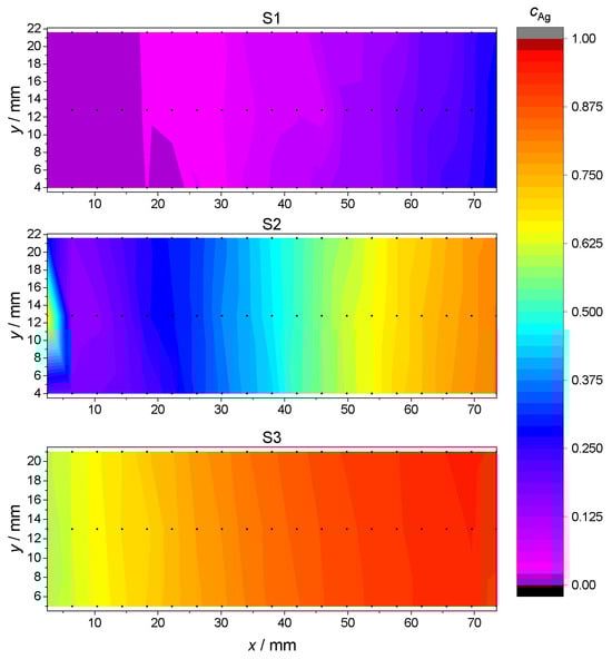
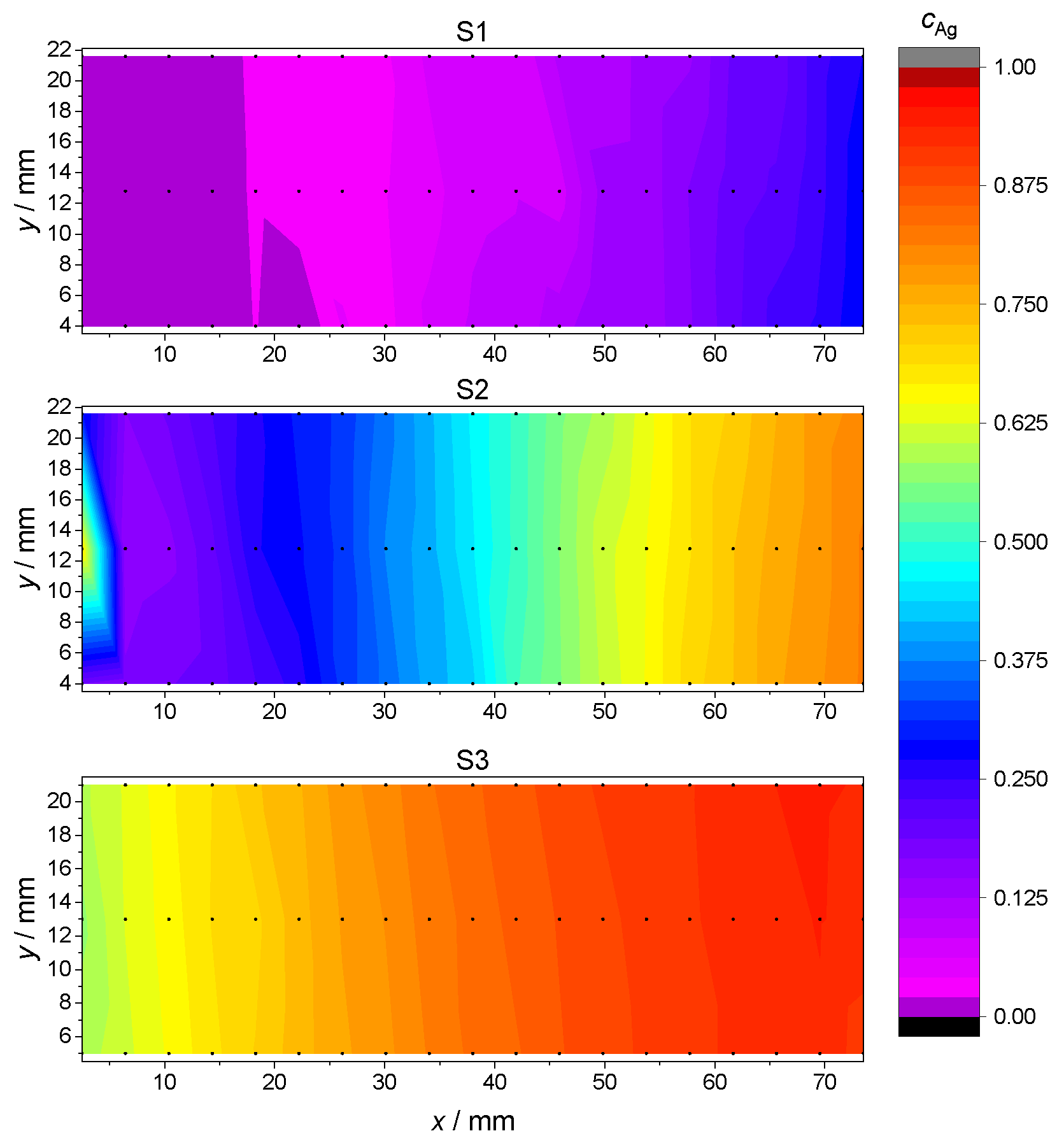
Figure 3.
Ag concentration for each sample S1, S2 and S3 as a function of location at the glass plate. Actual EDX measurements points are marked in black. Intermediate values are interpolated using the Renka–Cline method [38].
This measurement confirmed that the S1, S2 and S3 samples spanned, respectively, an atomic concentration of Ag in the range from 0 to , from to and from to , with a fairly constant Ag concentration along the shorter y dimension. In the discussion of subsequent measurements and data analysis, the Ag concentrations depending on the measurement points P1–P7 are the arithmetic average of the interpolated values along the y side for each point P1–P7. The so-obtained Ag concentration values as a function of measurement positions P1–P7 are reported in Table 3.
Table 3.
Atomic Ag concentration for the samples at each measurement point P1–P7. Reported values are an average along the y side of the strips, see text.
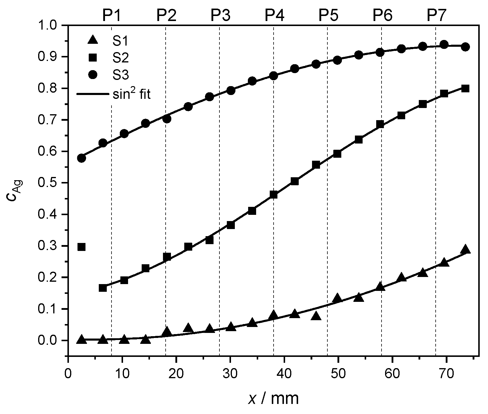
In order to highlight the quality of the concentration gradient within each sample, the measured Ag concentrations in the middle of the y direction (see measurement points in Figure 3) are fitted. Due to the geometry of the PVD setup, the concentration behavior along the x direction is expected to follow a trend [36] given by
The outcome of the numerical fit is shown as a continuous black line on top of the measured data in Figure 4. In Equation (2), the parameter stands for a concentration offset at . The fitting parameter accounts for the position where the curve reaches a minimum. The parameter A denotes the concentration range for each set of values. Finally, the parameter w is proportional to the FWHM of the curve and thus serves as a measure of width.
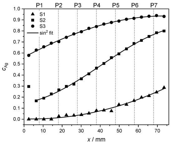
Figure 4.
Interpolated Ag concentrations from EDX measurements (see Figure 3) at the y center of each of the samples S1 (▲), S2 (■) and S3 (●), including a fit to Equation 2 (continuous black line, see text). The dashed lines mark the positions P1–P7 at which the film thickness and the fcc lattice parameter were measured.
For sample S1, the larger uncertainties in the fit can be explained by the narrower range of concentrations in comparison to the other samples, and thus, to relatively bigger fluctuations in the concentration values. The first measurement point of S2 was rejected for the fit to Equation (2) due to its unusually high Ag concentration, also visible in Figure 3. The corresponding data were, however, retained in other characterization and data analysis steps. The individual fitting parameters together with their uncertainties are reported in Table 4.
All samples appear to follow a concentration trend in good agreement with Equation (2). Since the subsequent XRD characterization is sensitive to the composition of each strip along its whole y side, the estimated stoichiometry at points P1–P7 is given in Table 3 by taking an average of the corresponding interpolated EDX values as described earlier.
2.4. Lattice Parameter via X-ray Diffraction (XRD)
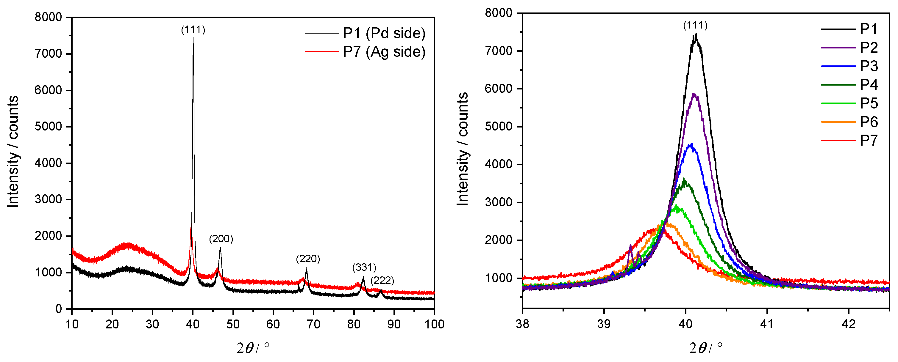
In order to confirm an fcc lattice structure and investigate the relationship between its lattice parameter and the Ag concentration, an XRD was performed at each measurement point P1–P7 along the three samples. Here, a Cu X-ray source ( nm) with Bragg–Brentano geometry was utilized. The lateral resolution of the X-ray beam of approximately 5 mm motivated the choice of spacing steps at 1 cm intervals along the x direction. Example results in the form of an XRD diffractogram from S1 are depicted in Figure 5. The left panel shows the diffraction intensity over a complete angular sweep for the two extremal points P1 (pure Pd, in black) and P7 ( at.%, in red).
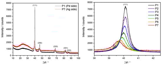
Figure 5.
XRD diffractogram of S1. Left panel: full angular sweep at the P1 (black) and P7 (red) measurement points. Right panel: detailed results around the main peak at , corresponding to reflection at Miller indices () = (1, 1, 1).
A clearly dominant peak appears at , corresponding to the Miller indices for an fcc unit cell. Other smaller peaks at diffraction angles of , , and are also visible and can be interpreted as originating from Ag and Pd for the Miller indices (200), (220), (311) and (222), respectively. A significantly wider and weaker peak round is a consequence of the borosilicate glass substrate. This analysis confirms the persistence of the fcc lattice geometry as the Ag concentration increases. A comparison of the P1 dataset with powder diffraction files (PDFs) for pure Pd [39] supports the assessment of having sufficiently thick films for bulk-like interpretation of the given results.
The right panel focuses on the main peak at , showing in particular its gradual drift towards smaller angles for higher concentrations of Ag.
The fcc lattice parameter for each diffractogram is calculated by evaluating the Bragg condition on the position of the main peak
where d is the distance between atomic layers in the direction of out-of-plane, is the angle of maximum intensity and n is the order of diffraction. Solving Equation (3) for d, under the assumption of and an fcc unit cell, yields the equation for the lattice parameter a:
Resulting values for the fcc lattice parameter as a function of Ag concentration are given in Table 5, and plotted together with literature data from Ref. [40] for cross-comparison in Figure 6.
Table 5.
The diffraction angle of maximum intensity and the corresponding fcc lattice parameter calculated via Equation (4) from XRD data acquired at the positions P1–P7 in all three samples S1, S2 and S3, see text.
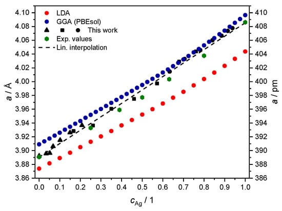
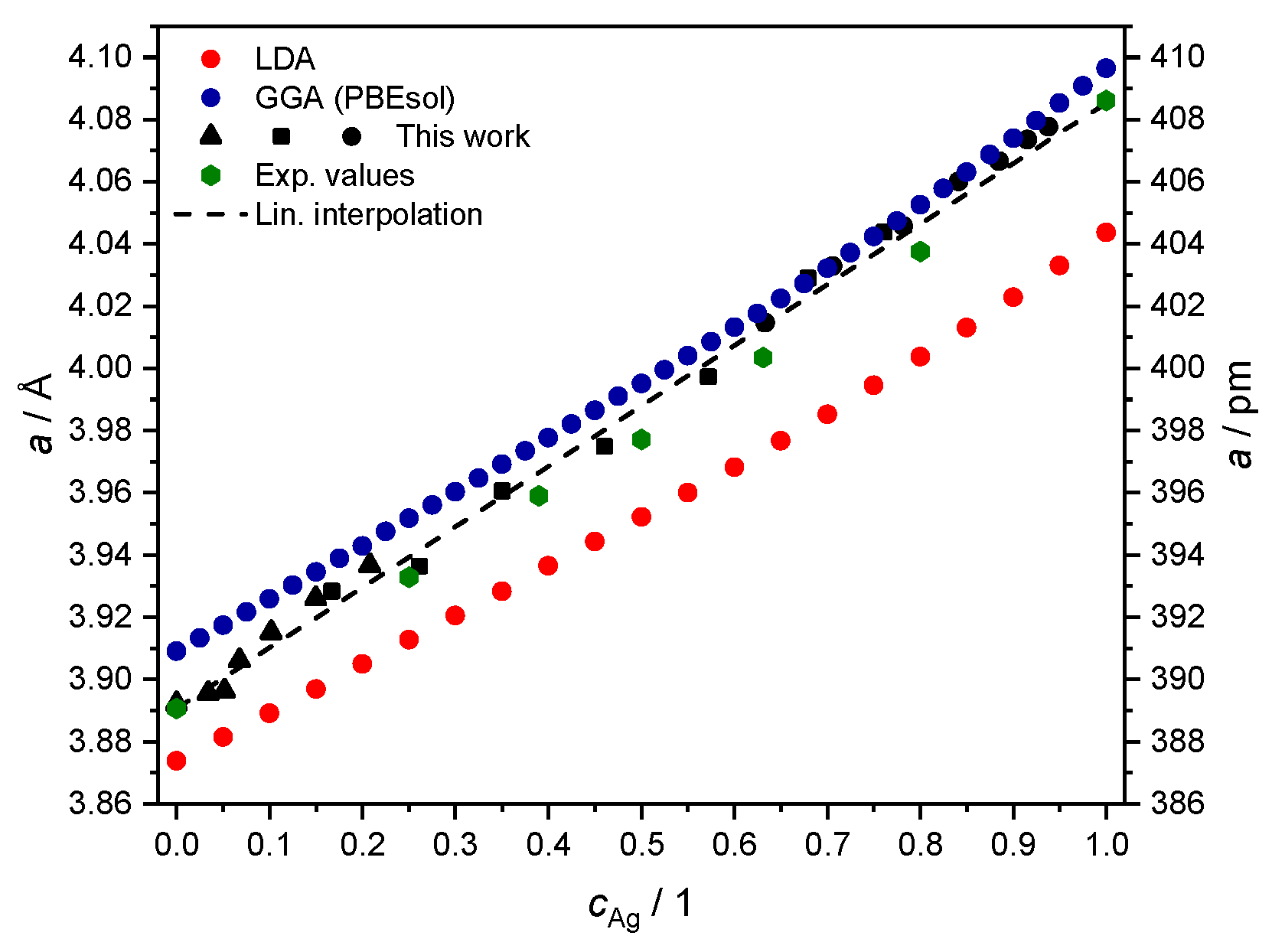
Figure 6.
Theoretical values of the fcc lattice parameter a, from fitting the equation of state with total energies computed with either LDA (red) or GGA-PBEsol (blue) adopted as exchange-correlation functional. Experimental values from Section 2.4 in black (▲ for S1, ■ for S2 and ● for S3) and from Ref. [40] (green hexagons) are plotted for comparison.
In this representation, the deviation in the literature values (green hexagons) from the simplified linear trend of Vegard’s law [41] is visible as a convexity in the estimated lattice parameter, always lying below the straight line between the and limits [40,42,43]. The data from the XRD measurement are comparable in magnitude but do not exhibit the expected deviation from Vegard’s law. We speculate that this may be due to contractive stress, also deemed responsible for the macroscopic shrinkhole defects visible in samples S1 and S2 (see Figure 1). Although further investigations may be needed to clarify this aspect of the problem in detail, we consider the agreement with other measurements of the fcc lattice parameter for the system good enough to be taken as input for the next numerical part of our study in Section 3.
3. Results from Ab Initio Calculations and Comparison
We calculated the ground state properties of the solid solution using DFT within the multiple scattering/Green’s function formulation [44]. Within this framework, different exchange-correlation functionals are made available by the LIBXC package [45] and we discuss the results from two possible choices in Section 3.1.
In a similar fashion, we compared the results for calculations of the electronic Bloch’s spectral function when using a scalar relativistic (SR) [34] and a fully relativistic (FR) [46] formulation of the Kohn–Sham problem.
The FR treatment adopts the relativistic Green’s function corresponding to the solution of the Dirac–Kohn–Sham Hamiltonian, rather than the spin-polarized SR Schrödinger Hamiltonian.
In all cases, we resorted to the coherent potential approximation (CPA) [47,48] in order to describe any intermediate value of c in the alloy without the discretization and the computational burdens posed by supercells of matching stoichiometry. Specific numerical parameters of particular relevance in controlling the quality of self-consistency are reported in the corresponding section below.
3.1. Total Energy Calculations and Estimate of Equilibrium fcc Lattice Parameter vs. Alloy Concentration
For each concentration value the DFT total energy was minimized over a set of 25 fixed values of the fcc lattice parameter a, assigned by linear interpolation of the literature values for pure Ag and pure Pd [42]. This part of the work resorted to the full-charge density approximation (FCDA) [49] for more realistic results compared to the muffin tin or atomic sphere approximations as discussed in, e.g., Ref. [29].
The quality of convergence was verified as a function, in particular, of sampling resolution in performing Brillouin zone integration for the valence charge density, and truncation in angular momentum for the Green’s function and multiple scattering expansion in spherical harmonics. Sufficient numerical quality appears to have been reached by using a sampling mesh of k-points over the whole Brillouin zone, and by representing the problem up to over the spherical harmonics basis set of the multiple scattering expansion.
We report here the results produced with either the local density approximation [50] (LDA) or the PBEsol version of the generalized gradient approximation [51] (GGA) as exchange-correlation functionals.
The corresponding set of 25 values for total energies vs. the lattice parameter was used as input for the numerical fit of the Birch–Murnaghan equation of state [52] to determine, in particular, the unit cell equilibrium volume and the bulk modulus (not discussed here), as detailed in Ref. [29]. This procedure to estimate the fcc lattice parameter a was repeated over 21 values of the Ag concentration (at steps of 5 at.%) for LDA calculations, and over 41 values (at denser steps of 2.5 at.%) for GGA (PBEsol) calculations. The outcome is plotted together with experimental data from Section 2.4 in Figure 6.
The procedure for the alloy yields the usual outcome of LDA, underestimating the equilibrium lattice parameter, as discussed in better detail in, e.g., Ref. [53]. The slope in dependence on Ag concentration is instead fairly similar, and it also reproduces the outcome of measurements from Section 2.4 and from the literature values from Ref. [40] (Figure 6). Both choices of the exchange-correlation functional lead to a larger deviation from the experimental data for high concentrations of Ag. This feature might be a consequence of how valence electrons are treated as non-interacting quasi-particles in DFT [54]. As revealed by XPS measurements of bulk Ag [55], this transition metal has a fairly localized DOS at the Fermi level, mainly associated with electrons. This makes it more challenging to handle correlation effects through the above local or semi-local DFT functionals [56], compared to the case of bulk Pd.
However, the calculated crystalline structure as a function of concentration is in a very good agreement with the current experiment. Therefore, we conclude that our computational approach can adequately describe the ground state properties of alloys. Next, we study further the electronic structure and transport properties using the PBEsol density functional in the full relativistic approach.
3.2. Electronic Topological Transitions via the BSF
We performed electronic BSF calculations using the effective potentials produced with the more realistic PBEsol exchange-correlation functional, and adopting the associated theoretical fcc lattice parameter discussed in Section 3.1 (see Figure 6).
The electronic structure of the alloy was examined at the Fermi level , adopting the same closed path on the surface of the first Brillouin zone (Figure 7) and other representation conventions as in Ref. [29]. Along the horizontal axis we show how results change over 41 values of the concentration, sampling the range from pure Pd to pure Ag at steps of 2.5 at.%. The resulting plot shows in color the appearance or disappearance of intensity peaks for the BSF, as it is recomputed along the chosen path across high-symmetry points (vertical axis).
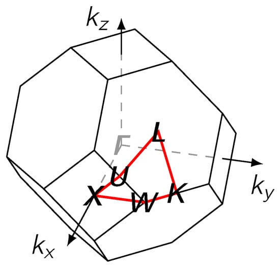
Figure 7.
The first Brillouin zone for an fcc lattice with the path along high symmetry points on the surface (red).
In particular, we identify the occurrence of an ETT at a certain concentration when either two BSF maxima merge or one BSF maximum splits as a function of varying Ag concentration. These results are compared upon employing either the SR (similar to Ref. [29]) or the FR treatment, in which one solves the Dirac Green’s function for electrons [46].
3.3. Relation to Resistivity
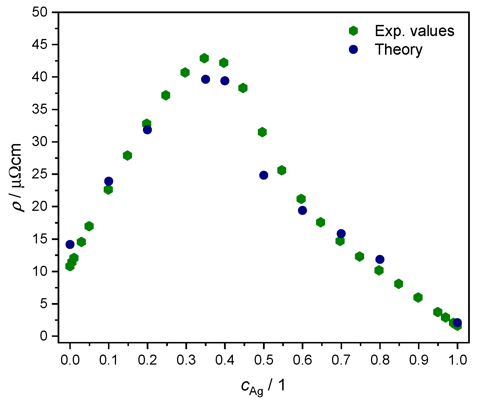
We adopted the linear response formalism of Ref. [57], inclusive in particular of disorder vertex corrections as implemented in the SPRKKR electronic structure code [44,58], to calculate the resistivity as a function of concentration for K. Due to the symmetries of the fcc lattice, the resulting conductivity tensor in is non-zero only along the diagonal [59], with alike values within numerical accuracy. The results are plotted in Figure 8 together with experimental values from Ref. [60]. We note the overall quantitative agreement, confirming the quality of the KKR-CPA effective medium description in representing the disordered AgPd alloy.

Figure 8.
Comparison of resistivity as a function of Ag concentration, between experimental values from Ref. [60] (green hexagons) and our own ab initio results from linear response theory for (blue circles); see text.
Here, our focus lies in studying the relationship between ETTs and the nonlinear changes in the resistivity of the AgPd alloy, as a function of Ag concentration. This is illustrated by plotting both the evolution of the BSF peaks at and the derivative of the as a function of Ag concentration (Figure 9 and Figure 10). The upper panel provides theoretical criteria to identify Ag concentration values for which ETTs occur. These are marked by vertical red lines placed in the middle of the concentration interval (red dashed lines) in which the corresponding ETT was found. The bottom panel highlights the possible concomitant variation in the measured electrical transport properties (here: resistivity) of the material.

Figure 9.
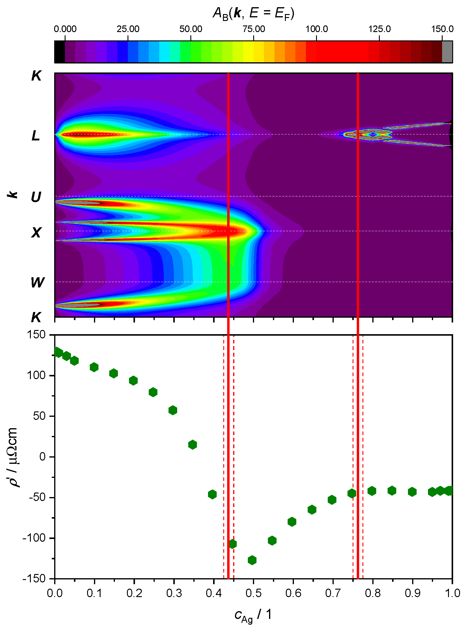
Top panel: intensity of the electronic BSF (color coded, in arbitrary units) along the path (vertical axis, see Figure 7) calculated in the SR approximation and plotted against Ag concentration (horizontal axis). Bottom panel: derivative of the experimental resistivity from Ref. [60]. Concentration intervals in which peaks have merged or split are marked by red dashed lines, with ETT estimated to occur in the middle (continuous red line).
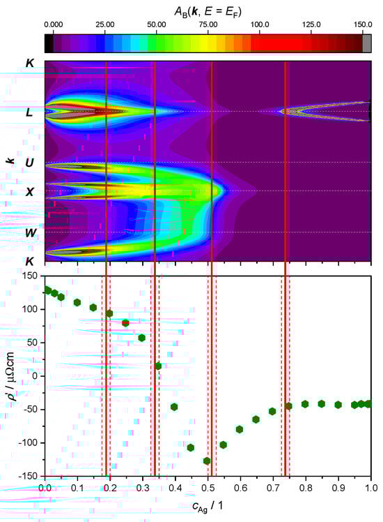
Figure 10.
Top panel: intensity of the electronic BSF (color coded, in arbitrary units) along the path (vertical axis, see Figure 7) calculated in the FR approximation and plotted against Ag concentration (horizontal axis). Bottom panel: same data as in Figure 9. Concentration intervals in which peaks have merged or split are marked by red dashed lines, with ETT estimated to occur in the middle (continuous red line).
The fully relativistic electronic structure of AgPd alloys, presented in Figure 11, indicates that the most important changes in the Fermi level happen along the path of the Brillouin zone.

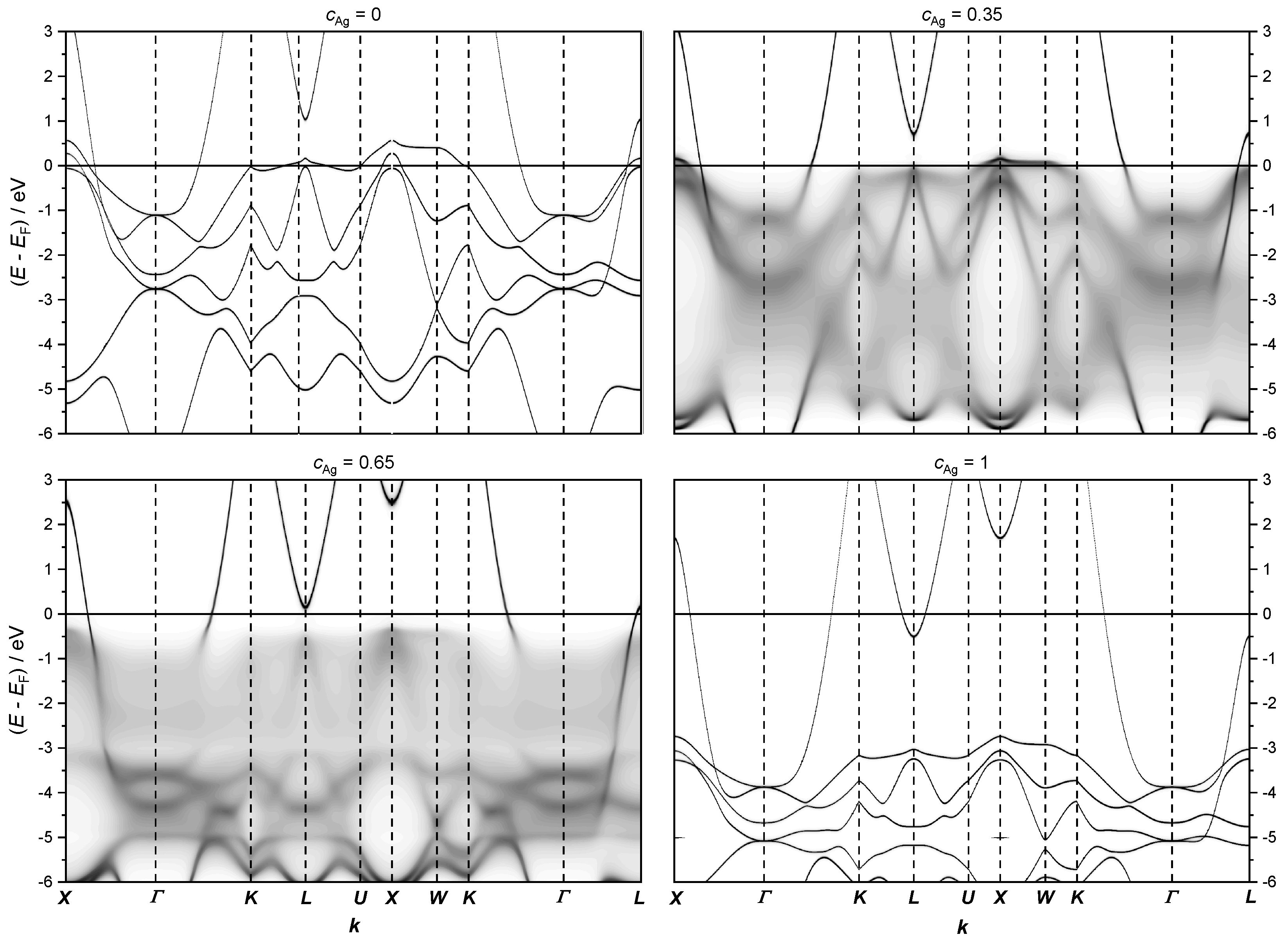
Figure 11.
The fully relativistic electronic structure of the AgPd alloy calculated along the path X − Γ − K − L − U − X − W − K − Γ − L on the first Brillouin zone (see Figure 7) for the concentrations = 0, 0.35, 0.65 and 1, respectively.
Note that the band structure below the Fermi level for = 0.35 and 0.65 appear blurred due to CPA.
At low Ag concentrations, the energy dispersion close to the Fermi level is mainly given by flat 4 d bands of Pd, which do not contribute much to the conductivity due to the low velocity of these states. Therefore, if these states are located at the Fermi level, the resistivity increases. According to our calculations, the flat Pd 4 d states cross the Fermi level in the range of Ag concentration between 0.3 and 0.5. To analyze the most important changes in the electronic structure at the Fermi level, the calculations were refined only along a path across the high-symmetry points for various concentrations of Ag (see Figure 9 and Figure 10).
It is noted that a quantitative estimate of transport properties by means of a mean free path treatment would involve an actual Brillouin zone volume integral.
We perform this comparison resorting to both the SR (as conducted in Ref. [29]) and the FR approximation for BSF calculations, using GGA (PBEsol) for the exchange-correlation functional and adopting the associated theoretical fcc lattice parameters from Section 3.1 (see Figure 6).
The SR treatment adopted in Figure 9 leads to the identification of only two topological transitions. The first one occurs between 42.5 at.% and 45.0 at.%, where a double peak around the -point merges as the amount of Ag increases. The second ETT occurs between 75.0 at.% and 77.5 at.%, where a new peak appears and then splits into two sharp peaks around the -point.
Looking at the derivative of the resistivity, we notice a minimum at 50 at.%, which could be associated with the first ETT. Another change in this slope around 75 at.% appears to correspond with the second ETT. No other ETTs are predicted by the SR approximation for the BSF. In particular, the kink in the curve around 25 at.%, as well as the maximum in the resistivity curve (i.e., 0) around 35 at.%, would remain unexplained.
Repeating the BSF calculations with the FR treatment (Figure 10) leads to the identification of two additional ETTs. Starting again from the 0, i.e., the pure Pd limit, the small-radius Fermi surface neck around the -point is now visible (see also Figure 2 in Ref. [28]). This feature shrinks with increasing Ag concentration and finally disappears between 17.5 at.% and 20.0 at.%. This change in electronic structure takes place at the same Ag concentration where the first slope change in the curve was noticed, around 25 at.%. The second additional ETT resolved by the FR treatment occurs between 32.5 at.% and 35.0 at.%. The two peaks around the point merge in a similar fashion as noted at 45 at.% in the SR outcome of Figure 9. The difference to the SR case is that in the FR picture, the double peak around the point merges before the broad peaks around and move towards the point. The resistivity of the alloy has its maximum at a similar value of the concentration 35 at.% (Figure 8), where the derivative passes through the zero. Considering the neighborhood of the point, with increasing Ag concentration the broad peaks coming from and move towards , producing again a double peak around the point . The forming of this double peak O=is completed before the Ag concentration has reached 50 at.% and merges into a single peak between 50 at.% and 52.5 at.%. This ETT can be associated with the minimum of the curve. An ETT in this concentration region was already visible in the SR outcome of Figure 9 (top panel), but it appears more spread-out in the FR treatment. The subtle change appears to correlate better with the minimum of at 50 at.%. The fourth and final ETT occurs with the merging of the peaks around the point between 72.5 at.% and 75.0% and is associated with the kink in the curve at 75 at.%.
An explanation of the mechanism relating changes in the alloy resistivity as a function of Ag concentration with the appearance of ETTs might be based on a mean free path model of electric transport [61]. This approach estimates the conductivity to be proportional to the product between the number of charge carriers at the Fermi level, their Fermi velocity and the inverse of the Bloch’s relaxation time due to disorder. All such parameters can, in principle, be quantitatively extracted from the BSF, and systematically compared with more accurate linear response calculations for the study of alloys as a function of composition [62].
The results from Figure 10 (upper panel) graphically suggest a decrease in the number of states at the Fermi level when the Ag concentration increases until the first ETT is produced around the point between 17.5 at.% and 20 at.%. Subsequently, spectral weight is mainly located around the region of the Brillouin zone, but it reaches much lower intensity and it shows large smearing as a function of disorder. Together, these two effects produce the resistivity maximum around 35 at.%. For higher Ag concentrations, the intensity remains approximately constant with a simultaneously increasing number of valence electrons. This suggests a higher number of charge carriers near the Fermi level, which is associated with a decrease in the resistivity with a constant slope up to 50 at.%, where another ETT occurs. The merging of the double peak causes fewer possible states at the Fermi level and causes the increasing slope of the resistivity. Finally, the slope of the resistivity remains roughly constant, i.e., the conductivity increases in linear fashion beyond 75 at.%. Since the intensity of the BSF remains approximately constant, this behavior can again be explained by a higher number of electrons at the Fermi level with increasing Ag concentration.
4. Conclusions
We have prepared, experimentally characterized and studied from first principles the prototypical solid solution alloy over the whole range of concentrations between the pure Pd and pure Ag limits.
Measurements of EDX and XRD confirm, respectively, that the thick film synthesis via PVD has achieved the desired continuous variation in stoichiometry and that samples have retained the fcc lattice structure for all compositions.
Ab initio calculations of total energies via DFT, and subsequent fitting of the Birch–Murnaghan equation of state, reproduce the experimental trend, in further agreement with the pre-existing literature [29,60].
We cross-compare this outcome upon using two different exchange-correlation functionals, LDA and GGA, and find the usual result of a better description of equilibrium lattice parameters with the second choice.
A good agreement of computed structural properties with the current experiment validates our first principles approach for treatment of the alloys. From this, further electronic and transport properties were calculated with the proposed density functional approach within the coherent-potential approximation.
We then considered the electric resistivity of the alloy, validating the quality of the CPA effective medium description by comparing the measurements with linear response calculations inclusive of disorder vertex corrections [57].
Finally, we examined the electronic structure of the alloy in terms of its BSF at the Fermi level, and studied, in particular, how ETTs appear as a function of concentration and seem to correlate with changes in the slope for the resistivity. The results comparing an SR and an FR treatment of the Kohn–Sham problem reveal a richer picture in the latter case, which follows more closely the above experimental changes in conductivity trends.
Author Contributions
Conceptualization, A.E. and M.H.; methodology, A.E., M.H. and A.W.H.; software, A.E., M.H., A.M. and F.R.; validation, A.I.M., C.C.M., A.W.H. and F.R.; formal analysis, F.R., A.I.M. and C.C.M.; investigation, F.R., A.I.M., C.C.M., A.W.H. and A.M.; resources, A.W.H. and A.E.; data curation, F.R. and A.M.; writing—original draft preparation, F.R.; writing—review and editing, A.M., F.R., A.W.H., A.E., M.H. and A.I.M.; visualization, F.R., M.H. and A.M.; supervision, A.E. and A.W.H.; project administration, A.E., M.H., F.R. and A.W.H.; funding acquisition, A.W.H. and A.E. All authors have read and agreed to the published version of the manuscript.
Funding
We gratefully acknowledge the financial support by the Austrian Federal Ministry of Economy, Family and Youth, the National Foundation for Research, Technology and Development (Christian Doppler Laboratory for Combinatorial Oxide Chemistry—COMBOX). The financial support received from the European Union Horizon 2020 through the project Medical Device Obligation Taskforce (MDOT) is gratefully acknowledged. MDOT received funding from the European Union’s Horizon 2020 research and innovation program under grant agreement number 814654. Arthur Ernst acknowledges funding by Fonds zur Förderung der wissenschaftlichen Forschung (FWF) grant I 5384. Calculations were partially performed at Rechenzentrum Garching of the Max Planck Society (Germany). This work was partially supported by the Czech Science Foundation (GA ČR) grant 23-04746S. Additionally, computing resources were supported by the project CEDAMNF CZ.02.1.01/0.0/0.0/15_003/0000358 (Ministry of Education, Youth and Sport), and by the “Information Technology for Innovation” (IT4I) grant OPEN-24-35.
Institutional Review Board Statement
Not applicable.
Informed Consent Statement
Not applicable.
Data Availability Statement
Data are contained within the article.
Conflicts of Interest
The authors declare no conflicts of interest. The funders had no role in the design of the study; in the collection, analyses, or interpretation of data; in the writing of the manuscript; or in the decision to publish the results.
References
- Kilty, P.; Sachtler, W. THE Mechanism of the selective oxidation of ethylene to ethylene oxide. Catal. Rev. 1974, 10, 1–16. [Google Scholar] [CrossRef]
- Doriot-Werlé, M.; Banakh, O.; Gay, P.A.; Matthey, J.; Steinmann, P.A. Tarnishing resistance of silver–palladium thin films. Surf. Coatings Technol. 2006, 200, 6696–6701. [Google Scholar] [CrossRef]
- Dellamorte, J.; Lauterbach, J.; Barteau, M. Palladium–silver bimetallic catalysts with improved activity and selectivity for ethylene epoxidation. Appl. Catal. A Gen. 2011, 391, 281–288. [Google Scholar] [CrossRef]
- Poizot, P.; Laffont-Dantras, L.; Simonet, J. The one-electron cleavage and reductive homo-coupling of alkyl bromides at silver–palladium cathodes. J. Electroanal. Chem. 2008, 624, 52–58. [Google Scholar] [CrossRef]
- Poizot, P.; Jouikov, V.; Simonet, J. Glassy carbon modified by a silver–palladium alloy: Cheap and convenient cathodes for the selective reductive homocoupling of alkyl iodides. Tetrahedron Lett. 2009, 50, 822–824. [Google Scholar] [CrossRef]
- Hassel, A.W. Pervasive electrochemistry. J. Solid State Electrochem. 2020, 24, 2083–2085. [Google Scholar] [CrossRef]
- Xu, Y.H.; Cai, Q.Q.; Ma, H.X.; He, Y.; Zhang, H.; Ma, C.A. Optimisation of electrocatalytic dechlorination of 2,4-dichlorophenoxyacetic acid on a roughened silver–palladium cathode. Electrochim. Acta 2013, 96, 90–96. [Google Scholar] [CrossRef]
- Khan, Z.; Dummer, N.F.; Edwards, J.K. Silver–palladium catalysts for the direct synthesis of hydrogen peroxide. Philos. Trans. R. Soc. A Math. Phys. Eng. Sci. 2018, 376, 20170058. [Google Scholar] [CrossRef]
- Han, N.; Sun, M.; Zhou, Y.; Xu, J.; Cheng, C.; Zhou, R.; Zhang, L.; Luo, J.; Huang, B.; Li, Y. Alloyed Palladium–Silver Nanowires Enabling Ultrastable Carbon Dioxide Reduction to Formate. Adv. Mater. 2021, 33, 2005821. [Google Scholar] [CrossRef]
- Cheng, Y.; Yeung, K. Palladium–silver composite membranes by electroless plating technique. J. Membr. Sci. 1999, 158, 127–141. [Google Scholar] [CrossRef]
- Chiang, W.-C.; Hilbert, L.R.; Schroll, C.; Tolker-Nielsen, T.; Møller, P. Study of electroplated silver–palladium biofouling inhibiting coating. Corros. Eng. Sci. Technol. 2008, 43, 142–148. [Google Scholar] [CrossRef]
- Kwon, J.D.; Lee, S.H.; Lee, K.H.; Rha, J.J.; Nam, K.S.; Choi, S.H.; Lee, D.M.; Kim, D.I. Silver-palladium alloy deposited by DC magnetron sputtering method as lubricant for high temperature application. Trans. Nonferrous Met. Soc. China 2009, 19, 1001–1004. [Google Scholar] [CrossRef]
- Quiroz, A.; Sato-Berrú, R.; Massoni, E.; Sánchez, R.; Bañuelos-Muñeton, J.; Sánchez-Flores, N.; Guerra, J.; Grieseler, R. Silver/palladium nanofilms for SERS application: Obtention and characterization. Mater. Chem. Phys. 2021, 273, 125065. [Google Scholar] [CrossRef]
- Kong, L.; Rui, G.; Wang, G.; Huang, R.; Li, R.; Yu, J.; Qi, S.; Wu, D. Preparation of Palladium/Silver-Coated Polyimide Nanotubes: Flexible, Electrically Conductive Fibers. Materials 2017, 10, 1263. [Google Scholar] [CrossRef] [PubMed]
- Wang, M.; Feng, Y. Palladium–silver thin film for hydrogen sensing. Sensors Actuators B Chem. 2007, 123, 101–106. [Google Scholar] [CrossRef]
- Løvvik, O.; Opalka, S.M. Reversed surface segregation in palladium-silver alloys due to hydrogen adsorption. Surf. Sci. 2008, 602, 2840–2844. [Google Scholar] [CrossRef]
- Petriev, I.S.; Frolov, V.Y.; Bolotin, S.N.; Baryshev, M.G.; Kopytov, G.F. A Surface-Modified Hydrogen-Permeable Palladium-Silver Plate. Russ. Phys. J. 2015, 58, 1044–1048. [Google Scholar] [CrossRef]
- Wald, K.; Kubik, J.; Paciulli, D.; Talukder, M.; Nott, J.; Massicotte, F.; Rebeiz, K.; Nesbit, S.; Craft, A. Effects of multiple hydrogen absorption/desorption cycles on the mechanical properties of the alloy system palladium/silver (wt%=10–25). Scr. Mater. 2016, 117, 6–10. [Google Scholar] [CrossRef]
- McLeod, L.; Degertekin, F.; Fedorov, A. Non-ideal absorption effects on hydrogen permeation through palladium–silver alloy membranes. J. Membr. Sci. 2009, 339, 109–114. [Google Scholar] [CrossRef]
- Züchner, H.; Barlag, H.; Majer, G. The existence of more than one jump process of hydrogen in palladium–silver alloys—An NMR study. J. Alloy. Compd. 2002, 330–332, 448–453. [Google Scholar] [CrossRef]
- Nishikawa, M.; Shiraishi, T.; Kawamura, Y.; Takeishi, T. Permeation Rate of Hydrogen Isotopes through Palladium-Silver Alloy. J. Nucl. Sci. Technol. 1996, 33, 774–780. [Google Scholar] [CrossRef]
- Bellanger, G.; Rameau, J.J. Tritium Adsorption and Diffusion of 25% Silver Palladium Cathodic Membranes for Water Processing. Fusion Technol. 1997, 31, 185–197. [Google Scholar] [CrossRef]
- Garino, T.; Rodriguez, M. Behavior of Silver and Palladium Mixtures during Heating. J. Am. Ceram. Soc. 2000, 83, 2709–2714. [Google Scholar] [CrossRef]
- Okazaki, J.; Ikeda, T.; Tanaka, D.A.P.; Sato, K.; Suzuki, T.M.; Mizukami, F. An investigation of thermal stability of thin palladium–silver alloy membranes for high temperature hydrogen separation. J. Membr. Sci. 2011, 366, 212–219. [Google Scholar] [CrossRef]
- Blanter, Y.; Kaganov, M.; Pantsulaya, A.; Varlamov, A. The theory of electronic topological transitions. Phys. Rep. 1994, 245, 159–257. [Google Scholar] [CrossRef]
- Bruno, E.; Ginatempo, B.; Guiliano, E.; Ruban, A.; Vekilov, Y. Fermi surfaces and electronic topological transitions in metallic solid solutions. Phys. Rep. 1994, 249, 353–419. [Google Scholar] [CrossRef]
- Bruno, E.; Ginatempo, B.; Giuliano, E.S. Fermi surfaces and electronic topological transitions in metallic random alloys. I. The influence on equilibrium properties. Phys. Rev. B 1995, 52, 14544–14556. [Google Scholar] [CrossRef] [PubMed]
- Bruno, E.; Ginatempo, B.; Giuliano, E.S. Fermi surfaces and electronic topological transitions in metallic random alloys. II. AgcPd1−c. Phys. Rev. B 1995, 52, 14557. [Google Scholar] [CrossRef] [PubMed]
- Hoffmann, M.; Marmodoro, A.; Nurmi, E.; Kokko, K.; Vitos, L.; Ernst, A.; Hergert, W. Elastic anomalies and long/short-range ordering effects: A first-principles investigation of the AgcPd1−c solid solution. Phys. Rev. B Condens. Matter. Mater. Phys. 2012, 86, 094106. [Google Scholar] [CrossRef]
- Mardare, A.I.; Yadav, A.P.; Wieck, A.D.; Stratmann, M.; Hassel, A.W. Combinatorial electrochemistry on Al-Fe alloys. Sci. Technol. Adv. Mater. 2008, 9, 035009. [Google Scholar] [CrossRef]
- Gonis, A. Green Functions for Ordered and Disordered Systems; North-Holland: Amsterdam, The Netherlands, 1992. [Google Scholar]
- Weinberger, P. Electron Scattering Theory for Ordered and Disordered Matter; Oxford University Press: London, UK, 1990. [Google Scholar] [CrossRef]
- Geilhufe, M.; Achilles, S.; Köbis, M.A.; Arnold, M.; Mertig, I.; Hergert, W.; Ernst, A. Numerical solution of the relativistic single-site scattering problem for the Coulomb and the Mathieu potential. J. Phys. Condens. Matter. 2015, 27, 435202. [Google Scholar] [CrossRef] [PubMed]
- Takeda, T. The scalar relativistic approximation. Z. Phys. B 1978, 32, 43–48. [Google Scholar] [CrossRef]
- Mardare, A.I.; Siket, C.M.; Gavrilović-Wohlmuther, A.; Kleber, C.; Bauer, S.; Hassel, A.W. Anodization Behavior of Glassy Metallic Hafnium Thin Films. J. Electrochem. Soc. 2015, 162, E30–E36. [Google Scholar] [CrossRef]
- Hafner, M.; Mardare, A.I.; Hassel, A.W. Vapour phase co-deposition of Al-Cu thin film alloys. Phys. Status Solidi A 2013, 210, 1006–1012. [Google Scholar] [CrossRef]
- Grüneisen, E. Theorie des festen Zustandes einatomiger Elemente. Ann. Phys. 1912, 344, 257–306. [Google Scholar] [CrossRef]
- Renka, R.J.; Renka, R.L.; Cline, A.K. A Triangle-Based C1 Interpolation Method. Rocky Mt. J. Math. 1984, 14, 223–237. [Google Scholar] [CrossRef]
- Kaszkur, Z. Powder diffraction beyond the Bragg law: Study of palladium nanocrystals. J. Appl. Crystallogr. 2000, 33, 1262–1270. [Google Scholar] [CrossRef]
- Rao, C.; Rao, K. Effect of temperature on the lattice parameters of some silver-palladium alloys. Can. J. Phys. 1964, 42. [Google Scholar] [CrossRef]
- Vegard, L. Die Konstitution der Mischkristalle und die Raumfüllung der Atome. Z. Phys. 1921, 5, 17–26. [Google Scholar] [CrossRef]
- Karakaya, I.; Thompson, W.T. The Ag-Pd (Silver-Palladium) system. Bull. Alloy Phase Diagrams 1988, 9, 237–243. [Google Scholar] [CrossRef]
- Bruno, E.; Ginatempo, B.; Giuliano, E.S. Quasi-particle lifetimes effects on deviations from Vegard’s rule in Ag-Pd disordered alloys. Nuovo Cim. D 1998, 20, 1367–1376. [Google Scholar] [CrossRef]
- Ebert, H.; Ködderitzsch, D.; Minár, J. Calculating condensed matter properties using the KKR-Green’s function method—Recent developments and applications. Rep. Prog. Phys. 2011, 74, 096501. [Google Scholar] [CrossRef]
- Lehtola, S.; Steigemann, C.; Oliveira, M.J.; Marques, M.A. Recent developments in LIBXC—A comprehensive library of functionals for density functional theory. SoftwareX 2018, 7, 1–5. [Google Scholar] [CrossRef]
- Strange, P.; Ebert, H.; Staunton, J.B.; Gyorffy, B.L. A relativistic spin-polarised multiple-scattering theory, with applications to the calculation of the electronic structure of condensed matter. J. Phys. Condens. Matter 1989, 1, 2959–2975. [Google Scholar] [CrossRef]
- Temmerman, W.; Szotek, Z. Calculating the electronic structure of random alloys with the KKR-CPA method. Comput. Phys. Rep. 1987, 5, 173–220. [Google Scholar] [CrossRef]
- Faulkner, J.S.; Stocks, G.M. Calculating properties with the coherent-potential approximation. Phys. Rev. B 1980, 21, 3222–3244. [Google Scholar] [CrossRef]
- Kollár, J.; Vitos, L.; Skriver, H. From ASA Towards the Full Potential. In Electronic Structure and Physical Properies of Solids; Dreyssé, H., Ed.; Springer: Berlin/Heidelberg, Germany, 2000; pp. 85–114. [Google Scholar] [CrossRef]
- Perdew, J.P.; Wang, Y. Accurate and simple analytic representation of the electron-gas correlation energy. Phys. Rev. B 1992, 45, 13244–13249. [Google Scholar] [CrossRef] [PubMed]
- Perdew, J.P.; Ruzsinszky, A.; Csonka, G.I.; Vydrov, O.A.; Scuseria, G.E.; Constantin, L.A.; Zhou, X.; Burke, K. Restoring the Density-Gradient Expansion for Exchange in Solids and Surfaces. Phys. Rev. Lett. 2008, 100, 136406. [Google Scholar] [CrossRef] [PubMed]
- Birch, F. Finite Elastic Strain of Cubic Crystals. Phys. Rev. 1947, 71, 809–824. [Google Scholar] [CrossRef]
- Haas, P.; Tran, F.; Blaha, P. Calculation of the lattice constant of solids with semilocal functionals. Phys. Rev. B 2009, 79, 085104. [Google Scholar] [CrossRef]
- Engel, E.; Dreizler, R. Density Functional Theory; Springer: Berlin/Heidelberg, Germany, 2014; Volume 32, pp. 72–77. [Google Scholar]
- Fadley, C.; Shirley, D. Electronic densities of states from x-ray photoelectron spectroscopy. J. Res. Natl. Bur. Stand. Sect. A Phys. Chem. 1970, 74A, 543. [Google Scholar] [CrossRef] [PubMed]
- Pavarini, E.; Koch, E.; Anders, F.; Jarrell, M. Correlated Electrons: From Models to Materials, 2nd ed.; Forschungszentrum Jülich GmbH: Jülich, Germany, 2012; Available online: https://core.ac.uk/download/pdf/34995382.pdf (accessed on 4 December 2023).
- Butler, W.H. Theory of electronic transport in random alloys: Korringa-Kohn-Rostoker coherent-potential approximation. Phys. Rev. B 1985, 31, 3260–3277. [Google Scholar] [CrossRef]
- Ebert, H.; Mankovsky, S.; Chadova, K.; Polesya, S.; Minar, J.; Ködderitzsch, D. Calculating linear-response functions for finite temperatures on the basis of the alloy analogy model. Phys. Rev. B 2015, 91, 165132. [Google Scholar] [CrossRef]
- Seemann, M.; Ködderitzsch, D.; Wimmer, S.; Ebert, H. Symmetry-imposed shape of linear response tensors. Phys. Rev. B 2015, 92, 155138. [Google Scholar] [CrossRef]
- Ho, C.Y.; Ackerman, M.W.; Wu, K.Y.; Havill, T.N.; Bogaard, R.H.; Matula, R.A.; Oh, S.G.; James, H.M. Electrical Resistivity of Ten Selected Binary Alloy Systems. J. Phys. Chem. Ref. Data 1983, 12, 183–322. [Google Scholar] [CrossRef]
- Butler, W.H.; Stocks, G.M. Calculated electrical conductivity and thermopower of silver-palladium alloys. Phys. Rev. B 1984, 29, 4217–4223. [Google Scholar] [CrossRef]
- Lowitzer, S.; Ködderitzsch, D.; Ebert, H.; Tulip, P.R.; Marmodoro, A.; Staunton, J.B. An ab initio investigation of how residual resistivity can decrease when an alloy is deformed. EPL Europhys. Lett. 2010, 92, 37009. [Google Scholar] [CrossRef]


Disclaimer/Publisher’s Note: The statements, opinions and data contained in all publications are solely those of the individual author(s) and contributor(s) and not of MDPI and/or the editor(s). MDPI and/or the editor(s) disclaim responsibility for any injury to people or property resulting from any ideas, methods, instructions or products referred to in the content. |
© 2024 by the authors. Licensee MDPI, Basel, Switzerland. This article is an open access article distributed under the terms and conditions of the Creative Commons Attribution (CC BY) license (https://creativecommons.org/licenses/by/4.0/).