Article

Influence of Interaction between Microcracks and Macrocracks on Crack Propagation of Asphalt Concrete

School of Architecture and Civil Engineering, Chengdu University, Chengluo Avenue No. 2025, Chengdu 610106, China
*
Author to whom correspondence should be addressed.
Materials 2024, 17(12), 2877; https://doi.org/10.3390/ma17122877
Submission received: 29 April 2024 / Revised: 31 May 2024 / Accepted: 11 June 2024 / Published: 12 June 2024
(This article belongs to the Section Construction and Building Materials)

Abstract

:
This paper aims to reveal the interaction relationship between microcracks and macrocracks and the influence of the interaction on the crack propagation behavior. A theoretical model of asphalt concrete was established for the interaction between microcracks with different crack densities and a macrocrack. And a meso-structure model of AC-13 dense-graded asphalt concrete was established by combining the Talyor medium method and the DEM (discrete element method). Macro and micro parameters, such as the stress–strain characteristics, crack evolution parameters, and crack tip stress field, were obtained through a semi-circular bend virtual test and used to study the characteristics of crack propagation under the interaction between microcracks and the macrocrack. The results indicate that the interaction has an effect throughout the process of asphalt concrete damage, and shows shielding and acceleration effects as the microcrack density changes. When the microcrack density is low (f3 ≤ 0.8), the crack propagation process, which is affected by the interaction effect, exhibits significant differences, and the interaction effect shows the shielding effect. When the microcrack density is high (f3 > 0.8), the fracture stage is mainly affected by the interaction effect, which shows the acceleration effect. The results provide a predictive theoretical and numerical model for low-temperature cracking of asphalt pavement, and theoretical support for the design, maintenance, and upkeep of long-life pavement.

1. Introduction

Asphalt concrete is a non-homogeneous composite material with a specific spatial structure. It is a mixture of asphalt mortar, aggregates, and voids. Traditional laboratory tests were carried out to reveal the relationship between fatigue cracking of the asphalt concrete and various factors, such as different additives [1], fiber content [2], and reclaimed asphalt pavement (RAP) content [3]. Moreover, combined with ENDB (Edge Notched Disc Bend) and SEM (Scanning Electron Microscopy), it revealed the effect of asphalt-to-cement ratio (A/C) on the stress intensity factor of materials [4]. Moreover, aiming at warm mix asphalt (WMA), the viscoelastoplastic continuum damage (VEPCD) model was established to illustrate the cracking sensitivity of asphalt concrete [5]. And the four-point bending test [6] was carried out to analyze the effect of mineral additives on the asphalt concrete viscoelastic behavior from the density, gradation, and strength properties, respectively.
However, because of the microcrack randomness in the spatial distribution of asphalt concrete, the stress field is different from the stress field of asphalt concrete with a single crack, ultimately leading to changes in the fracture behavior of asphalt concrete [7,8]. The Muskhelishvili complex function method [9,10], the small parameter method [11,12,13], the distribution dislocation method [14], the averaging method [15], and the crack line method [16] have been used to obtain the analytical solution of the stress intensity factor of co-linear double cracks and cyclic co-linear multi-cracks in an infinitely large flat plate under uniform load and concentrated load. These methods have also been used to determine the connection between the interaction effect and crack propagation from the perspective of the special distribution of microcracks. However, in practical engineering, the randomness of the spatial distribution of microcracks hinders the calculation of the analytical solution of the stress intensity factor.
Therefore, in studying the impact of penetrating crack clusters and surface crack clusters on macrocrack extension evolution, cracks have been mainly assumed to be in-plane cracks or surface cracks under plane stress or plane strain conditions. Jiang [17,18] and Renshaw [19] used the projection method to establish a wing-like double-crack model by consolidating the penetrating crack group into a single crack. The model was used to investigate the effect of double-crack interactions and the interaction mechanism between secondary crack populations and macrocracks, considering parallel equal-length edge cracks and parallel unequal-length centering cracks, respectively. Moreover, the wing-like double-crack model has been applied to parallel-biased double cracks [20], co-linear or biased double cracks [21], short cracks [22], and triple co-linear cracks [23], respectively, where the interaction mechanism between penetrating crack groups and main cracks was determined by analyzing the influence of penetrating crack groups on the main crack propagation. Additionally, Kamaya [24] merged surface crack clusters into a single crack using the envelope method; the author considered the relative position of the double cracks to reveal the shielding effect of parallel surface-biased double cracks on the macrocrack propagation. Moussa [25] considered the size of double cracks to analyze the influence of the load type on the shielding effect of the parallel surface-biased double cracks. Meanwhile, from the perspective of secondary surface cracks, studies have revealed the influence of the depth of the secondary surface crack on the interaction effect between the secondary surface crack and the deflected primary crack [26,27,28].
The Finite Element Method (FEM) and lab tests have also been combined to study the shielding effect of coplanar double cracks on macrocrack extension, considering various factors, such as microcrack spacing [29,30], the relative spacing between cracks [21,31], crack size [32], and crack depth [33]. The local fracture energy index was utilized to characterize the transient impact of a specific number of randomly distributed microcracks on macrocrack propagation through the integration of Digital Image Technology (DIT) and Acoustic Emission (AE) [34]. The FEM was used to introduce microcracks with a consistent orientation in the constant and crack extension regions to establish the correlation between macroscopic crack extension and toughening mechanisms from the perspective of the number of microcracks [35]. Furthermore, from the perspective of the toughening modulus of fiber-reinforced composites, the toughening effect of different microcracks with a unidirectional distribution was determined by analyzing the effect of unidirectionally distributed microcracks on the macrocrack propagation considering different fiber spatial orientations [36].
In summary, most studies have focused on revealing the effect of the interactions between the penetrating double crack, the surface (buried) double crack, and the main crack. These studies have primarily used the projection method or envelope method, which combines a group of microcracks into a single crack. Meanwhile, a combination of lab experiments and the FEM has been used to describe the toughening effect of microcracks in terms of microcrack amount and orientation. However, changes in the stress field at the macrocrack tip resulting from the microcracks’ randomness in the spatial distribution of asphalt concrete influence the evolutionary behavior of the macrocrack’s extension.
Therefore, according to previous research results, the AC-13 suspended dense structural asphalt concrete at −20 °C was taken as the research object in this study. The Talyor medium method and the discrete element method (DEM) were combined to establish a meso-structural model of asphalt concrete with different microcrack densities; crack density was introduced to characterize the spatial distribution of the model’s internal microcracks. Additionally, the virtual semi-circular bend (SCB) was used to analyze the influence of different crack densities on the propagation behavior of the macrocrack considering macro and micro parameters, such as stress–strain curve, effective modulus change, and crack zone stress field. Moreover, we established the relationship between the distribution characteristics of microcracks and the interaction effect between cracks.

2. Effective Modulus of Asphalt Concrete

2.1. Influence of Morphological Characteristics of Macrocracks

Under the action of loading, changes in the macrocrack configuration of asphalt concrete result in corresponding changes in the free energy of the material, which alters the fracture form of the asphalt concrete. The macrocrack in the asphalt concrete is taken as a representative volume element (RVE), assuming that the macrocrack has an initial deflection angle β, a short axis size c, and a long axis size r in the other two directions (as shown in Figure 1). Thus, the geometrical properties of the crack can be defined by Equation (1).
Based on the Tanaka–Mori theory [37], the effective modulus ET of asphalt concrete containing a thin elliptical crack can be expressed as follows:
E T E = 1 1 + f 1 f 2 ( 4 ( 1 v ) r π c )
where f1 and f2 denote the volume fractions of the main crack and asphalt concrete, respectively, and f1 = 1 − f2; ν denotes the Poisson’s ratio of the material; E denotes the modulus of the undamaged asphalt concrete; and ET denotes the effective modulus of the asphalt concrete containing the main crack.
The geometric parameters of thin elliptical cracks can also be expressed as the ratio between the volume fraction f1 and the crack shape ratio α:
f 1 α = 4 π r 2 c 3 l 1 2 l 3 · r c = 4 3 π p 3 2 tan β
where p = πr2/ l 1 2 represents the ratio of the crack area to the bottom area of the representative volume unit RVE; tanβ = l1/l3 represents the length–height ratio of the representative volume unit RVE, which is related to the initial deflection angle of the crack β (the angle between the direction of the main crack and the direction of the load loading), 0° ≤ β ≤ 90°; α denotes the shape ratio of the thin ellipsoidal crack; and α = c/r.
The following ratio can be obtained by combining Equations (1) and (2):
E T E = 1 1 + 16 ( 1 v ) tan β 3 f 2 ( p π ) 3 2
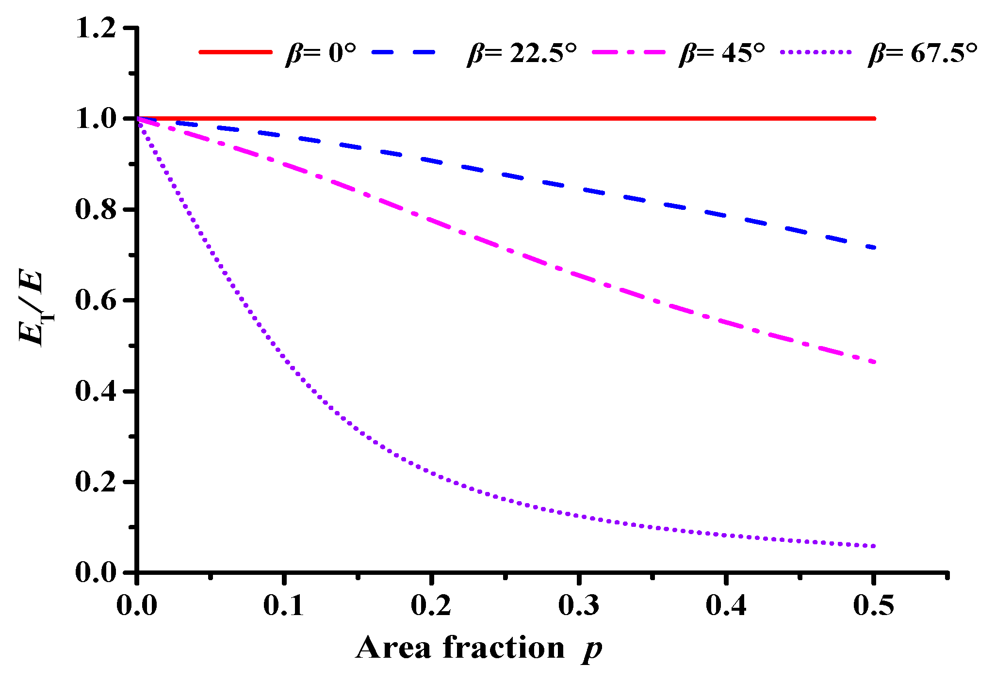
From Equation (3), for asphalt concrete with thin elliptical cracks, the effective modulus ET is related to the crack length r and the distribution state of the cracks in space. The Poisson’s ratio v of asphalt concrete generally ranges between 0.25 and 0.45; and the majority of the existing studies assumed a constant Poisson’s ratio value of 0.35 [38,39]. Besides considering the Poisson’s ratio of asphalt concrete decreases in the low-temperature condition, the Poisson’s ratio v = 0.3 is taken as an example. Meanwhile, for asphalt concrete containing only a single macrocrack, the volume fraction of its macrocrack is negligible, i.e., f2 = 1. Equation (3) shows the relationship between the area fraction p, crack deflection angle β, and effective modulus ET of asphalt concrete, which is illustrated in Figure 2.
Figure 2 shows that at a fixed initial deflection angle β, the effective modulus of asphalt concrete decreases slowly and nonlinearly as the area fraction p increases gradually. Additionally, at a fixed crack length r, the effective modulus of asphalt concrete decreases significantly as the initial deflection angle β decreases. The figure also shows that in terms of the geometric size of the main crack, its initial deflection angle β greatly affects the effective modulus of the asphalt mixture.

2.2. Influence of Interaction Effect between Microcracks and the Macrocrack

The following assumptions are made regarding microcracks at the tip of the macrocrack in asphalt concrete [40]:
  • Each microcrack is uniformly open, without considering microcrack closure and crack surface friction;
  • The microcrack orientation is random and no dominant microcrack orientation exists;
  • Only weak interactions exist between neighboring microcracks.
Accordingly, by combining Equation (3) with the Talyor medium method [41], a connection can be established between the effective modulus of asphalt concrete and the interaction effect between microcracks and the macrocrack:
E E T = 1 + f 3 16 ( 1 v 2 ) ( 10 3 v ) 45 ( 2 v ) E E T 1
where E′ denotes the effective modulus of asphalt concrete containing microcracks and the macrocrack; and f3 denotes the crack density parameter of the microcracks, which is related to the number of cracks, crack orientation, and crack geometry parameters.
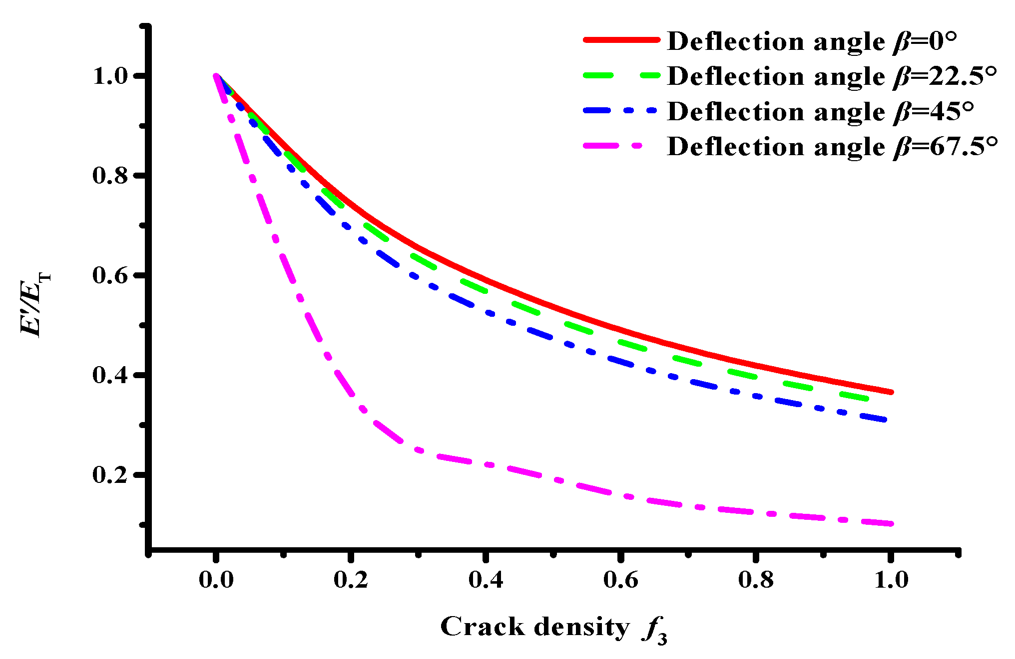
Based on Equation (4), the variation curve between the effective modulus and crack cluster density of asphalt concrete containing microcracks and the macrocrack can be obtained, as shown in Figure 2.
The interaction between internal microcracks and the macrocrack in asphalt concrete intensifies as the microcrack density f3 and deflection angle β (see Figure 3) increase. Notably, the interaction effect between the internal microcracks and the main crack is the most significant when the deflection angle β is greater than 45°.
To further illustrate the changes in the interaction effect between microcracks and the macrocrack, the Talyor medium method and the DEM were used to establish the meso-structural model of asphalt concrete with a macrocrack and microcracks of different densities. Through an SCB virtual test, the correlation between a multi-crack interaction effect and macrocrack propagation was established in terms of effective modulus change, main crack propagation evolution process, and crack tip stress field change.

3. Meso-Structural Model of Asphalt Concrete with Different Crack Distribution Characteristics

3.1. Asphalt Concrete Meso-Parameters

According to the research results of the low-temperature laboratory test [42], the gradation of the AC-13 suspended dense structural asphalt concrete is shown in Table 1. And the asphalt adopts PPA-SBS (polyphosphoric acid and styrene butadiene styrene) composite-modified asphalt; its performance grade (PG) is PG 70–28 and the SBS and PPA content is 3% and 1%, respectively. And physical indicators of AC-13 asphalt concrete is shown in Table 2.
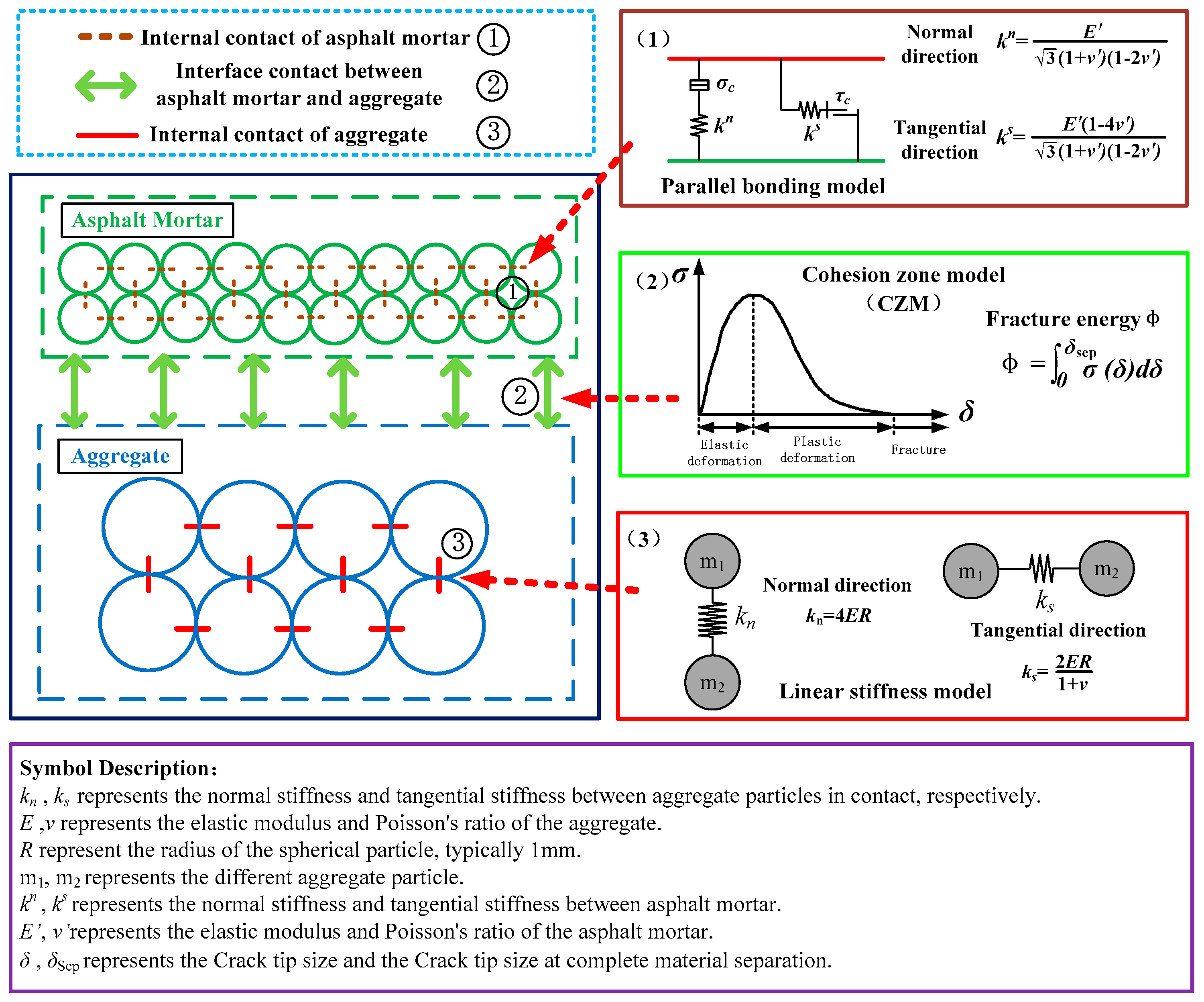
The discrete element meso-structural model of asphalt concrete mainly includes three contact interfaces: the contact between coarse aggregate particles, the contact within the asphalt mortar, and the contact between coarse aggregate particles and asphalt mortar. Therefore, to analyze the crack propagation characteristics of asphalt concrete, the appropriate mechanical model of different contacts [43] should be determined, as shown in Figure 4.
Because aggregates are purely elastic materials, the stiffness model of the contact between aggregates can be described by a spring element, i.e.,
k n = 4 E s R k s = 2 E s R 1 + v s
where kn, ks denote the normal stiffness and tangential stiffness between aggregate particle contacts; Es, νs denote the dynamic modulus and Poisson’s ratio of the aggregate, respectively. R denotes the radius of spherical particles, which is generally taken as 1 mm. As reported in previous studies [44,45], the dynamic modulus, Poisson’s ratio, tensile strength, and coefficient of internal friction of basaltic crushed rock were taken as 55.5 GPa, 0.25, 27.6 MPa, and 0.5, respectively.
Meanwhile, the parallel bond model and the CZM (Cohesive Zone Model) were used to describe the contact behavior between asphalt mortar particles and that between the asphalt mortar and aggregates [46], i.e.,
k n = E a 3 ( 1 + ν a )   ( 1 2 ν a ) k s = E a ( 1 4 ν a ) 3 ( 1 + ν a ) ( 1 2 ν a )
where kn, ks represent the internal normal and tangential stiffness of asphalt mortar; Ea, νa represent the dynamic modulus and Poisson’s ratio of asphalt mortar, respectively.
For the contact characteristics of asphalt mortar and aggregate particles, the magnitude of the contact force σ between the particles was calculated by tracking the particle position, rotation angle, contact force between particles, and stress measurement circle, i.e.,
σ = ( σ c n ) 2 + ( τ c n ) 2
where σ c n and τ c n represent the components of the contact force between particles in the normal and tangential directions, respectively.
The maximum contact force σmax between particles can be obtained from the normal force σc, tangential force τc, and the angle α between the direction of contact force and the line through the particle center, i.e.,
σ max = ( 1 2 α π ) × σ c + 2 α π × τ c
When the inter-particle contact force σ exceeds the maximum contact force σmax, the inter-particle contact begins to yield or weaken, which indicates a decay in the inter-particle contact force.
The indirect tensile test and the dynamic modulus test were carried out to obtain the mechanical properties of AC-13 asphalt concrete, as shown in Figure 5, Table 3 and Table 4. According to Equations (5)–(8), the meso-mechanical parameters of each material phase at a low temperature of −20 °C are shown in Table 5.

3.2. Construction of Microcracks and the Macrocrack

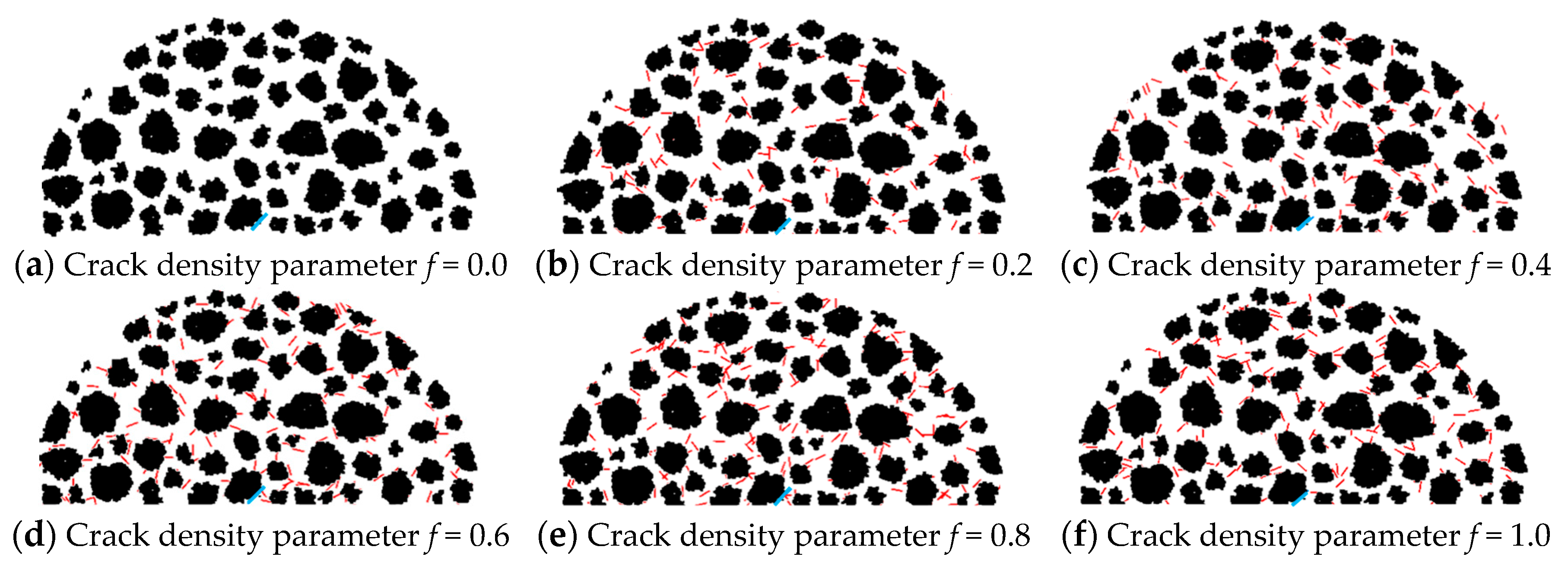
On the PFC2D 5.0 software, using the DEM and the Talyor medium method, a semicircular meso-structural model of asphalt concrete with a radius of 75 mm was established. The macrocrack and microcracks with a uniform randomly distributed location and orientation were constructed using the dfn template and dfn generate commands. Abrupt changes occur in the interaction effect between microcracks and the macrocrack when the macrocrack deflection angle β ≥ 45° (see Figure 2). Hence, β = 45° and crack length r = 2 mm were considered. Meanwhile, the crack sizes of microcracks were all considered to be 1 mm based on the Talyor medium method, and the crack densities f3 were taken as 0.0, 0.2, 0.4, 0.6, 0.8, and 1.0, respectively.
Figure 6 shows the meso-structural model of asphalt concrete that contains a macrocrack and microcracks of different crack densities. The black particles represent the internal aggregate of asphalt concrete, the red lines represent microcrack clusters, and the blue lines represent the macrocrack (see Figure 6).

3.3. SCB Virtual Test

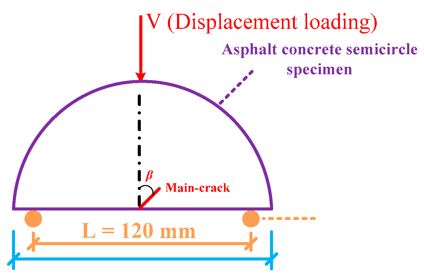
The SCB virtual test of asphalt concrete containing microcracks and a macrocrack (see Figure 7) was performed using the discrete element analysis platform. Two rigid spherical particles were used as pivot points with a spacing L of 120 mm; the load was applied by a constant displacement loading of 1 mm/min.

4. DEM Results Analysis

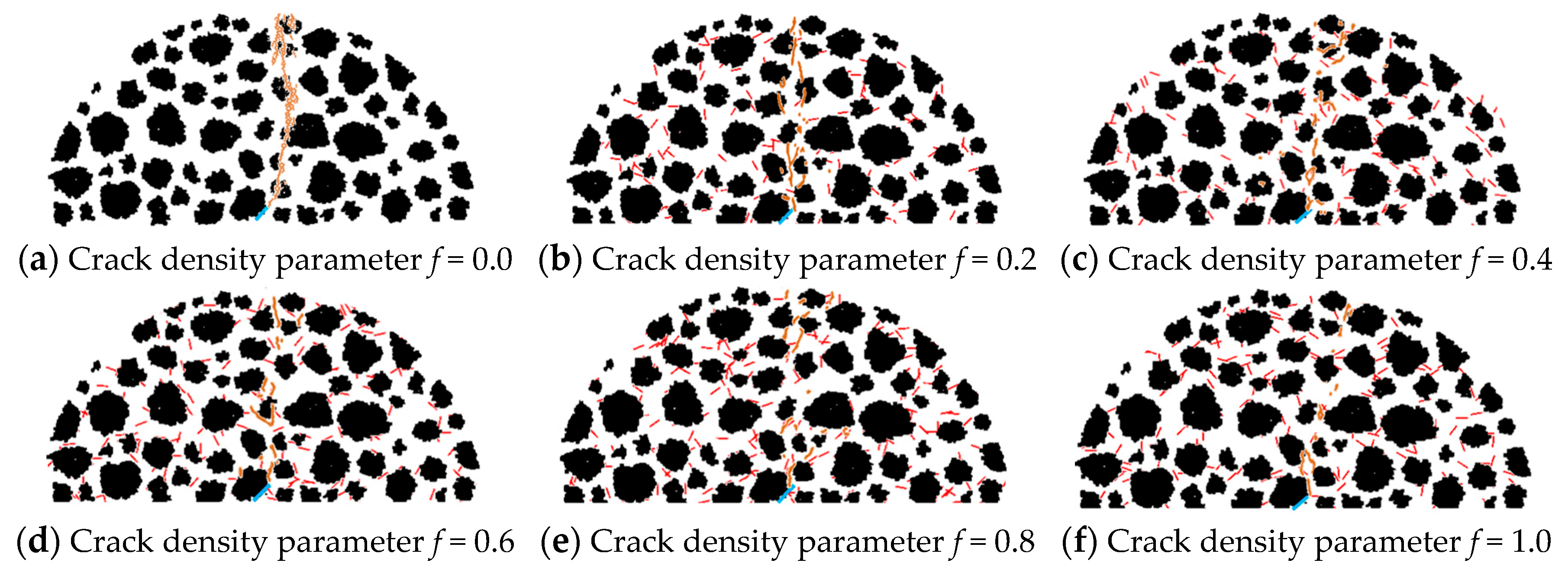
The SCB virtual test was conducted for asphalt concrete containing macrocracks with different microcrack densities f3 by the discrete element analysis platform (PFC2D). The results are shown in Figure 8, where the solid orange line indicates the crack extension in the material.
It is obvious that there is a large difference in the spatial distribution of the internal crack propagation (see Figure 8), which indicates that the interaction effect between microcracks and the macrocrack changes as the density of microcracks changes.
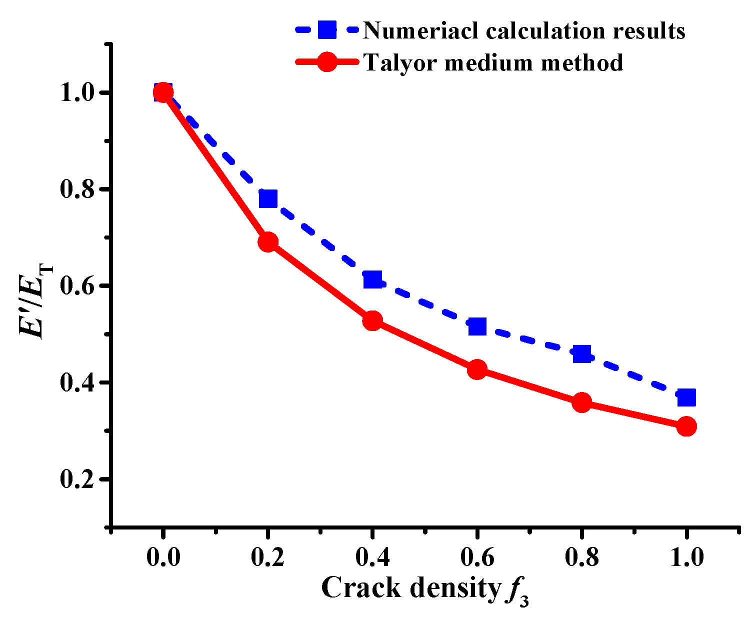
Moreover, the numerical simulation results show the variation curve of the effective modulus of asphalt concrete with a microcrack density of f3, as shown in Figure 9. It can be seen in Figure 9 that the effective modulus of asphalt concrete with a macrocrack has a nonlinear decreasing trend as the microcrack density f3 increases. A good correlation exists between the numerical calculation results and the theoretical calculation results of the Talyor medium method, which indicates that the numerical calculation is accurate.
To further analyze the influence of the interaction effect between the microcracks and macrocrack cracks on the macrocrack propagation, the stress–strain relationship, crack extension process, and crack tip stress field are analyzed in the following subsections.

4.1. Stress–Strain Curve

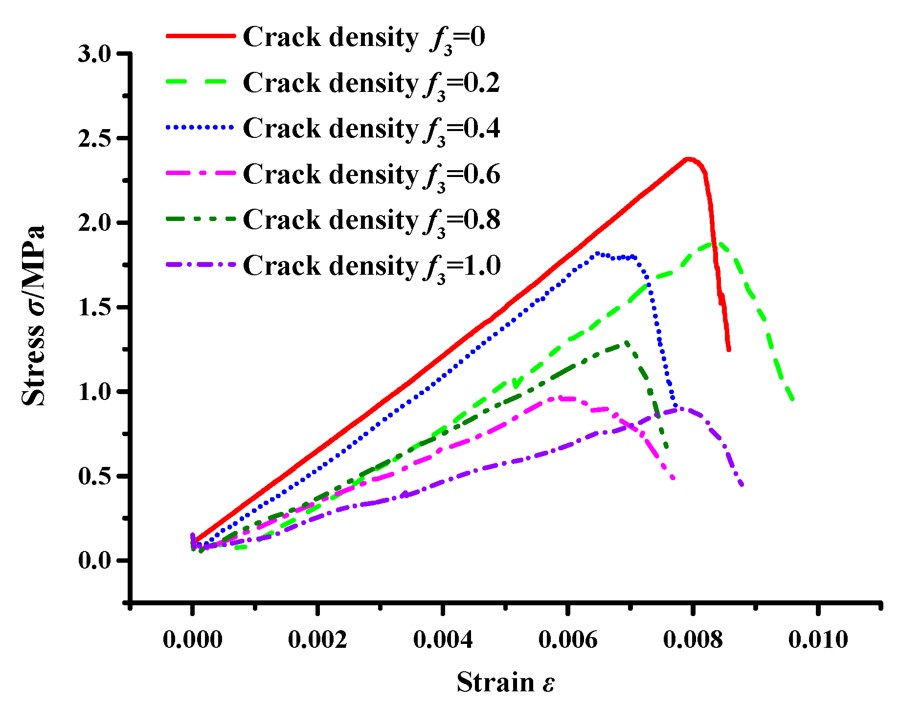
The stress–strain variation was monitored by stress measurement circles, and the result is illustrated in Figure 10.
Figure 10 shows that the interaction between microcracks and a macrocrack influences crack propagation until fracture failure occurs in the asphalt concrete, and the interaction effect is substantial. When the crack density f3 ≤ 0.4, no obvious changes are observed in the fracture stress of the asphalt concrete, meaning that the interaction effect is weak, i.e., the interaction has no obvious effect on the macrocrack propagation (see Figure 8). Moreover, the result also indicates that the interaction at this crack density mainly reduces the effective modulus of the asphalt concrete (see Figure 9).
On the other hand, the interaction effect is enhanced when the crack density f3 ≥ 0.6, resulting in changes in the crack propagation (see Figure 8); meanwhile, the stress during the damage of asphalt concrete increases and then decreases, that is, the interaction has a shielding effect and an acceleration effect on the internal crack propagation of the material. The shielding and acceleration effects are clearly observed from the parameters related to the crack propagation.

4.2. Crack Propagation Process

On the discrete element analysis platform (PFC2D), the crack propagation monitoring procedure was used to determine the crack behavior during the asphalt concrete fracturing in real time. The number of cracks was characterized by the number of particle contact failures in the material; this means that the more particle contact failures, the more the material cracks, indicating that greater energy is required to destroy the asphalt concrete, i.e., the cracking strength of the asphalt concrete is greater.
Therefore, the logarithm and increment of the time step represent the time elapsed at the crack incubation stage, expansion stage, and fracture stage, respectively [47], as shown in Table 6.
Table 6 shows that the increase in the crack density results in a gradual decrease in the crack incubation time, meaning the interaction effect shortens the crack incubation time and speeds up the crack nucleation. Moreover, the table also shows that at the crack extension stage, no significant difference exists in the crack propagation and failure process times when the crack density f3 ≤ 0.4, further indicating that the interaction effect is weak.
Meanwhile, when the crack density f3 ≥ 0.6, the time elapsed at the crack extension stage decreases with the increase in crack density; the time elapsed at the fracture stage increases and then decreases (see Table 6). Moreover, the longest elapsed time at the crack extension stage was at the crack density f3 = 0.6, indicating that the interaction delays the crack extension process; when the crack density f3 = 0.8, the time elapsed at the fracture stage reached a maximum, meaning the interaction prevents the formation of macroscopic cracks. This result indicates that under these crack densities, the interaction has a shielding effect. Otherwise, at the crack density f3 = 1.0, a significant decrease occurs in the time elapsed at the crack extension and fracture stages, indicating that the interaction accelerates the crack propagation to macroscopic crack formation, i.e., it has an acceleration effect.
To reveal the generation mechanism of the interaction between microcracks and macrocracks, we analyze the changes in the stress field on the crack tip domain in the following subsection.

4.3. Stress Field Analysis for Crack Tip Domain of Main Crack

The subroutine was designed using FISH to identify the stress field of asphalt concrete. The stress field force chain diagrams were obtained, as shown in Figure 11: the red line represents the average tensile stress field and the blue line represents the average shear stress field. The area ratio of the stress field was extracted, as shown in Figure 12.
Figure 11 and Figure 12 show significant changes in the tensile field, unlike the shear field, which only changes slightly. This result indicates that as the crack density increases, the interaction causes the asphalt concrete failure to change from tensile stress failure to shear stress failure. However, when the crack density f3 = 0.6 and 0.8, the increments of the tensile field and shear field (see Figure 12b) indicate that the crack shielding effect predominantly causes tensile stress damage to the asphalt concrete, delaying the macroscopic crack formation (see Table 6) and increasing the low-temperature crack resistance of the asphalt concrete (see Figure 10).
Meanwhile, Figure 11 and Figure 12 also show that the area ratio of the tensile field and the area ratio between the tensile and shear fields decreases considerably when the crack density f3 = 1.0. This illustrates that the interaction predominantly induces shear stress damage to the asphalt concrete, which accelerates the crack propagation to a macroscopic crack formation (see Table 6).

5. Conclusions

A meso-structural model of asphalt concrete with a macrocrack and microcracks of different crack densities was established using the Talyor medium method and DEM. An SCB virtual test was conducted to analyze the influence of the interaction between microcracks and macrocracks on crack propagation. The analysis considered factors such as effective modulus, stress–strain curve, crack propagation process, and stress field. The conclusions are as follows:
(1)
A good correlation exists between the Talyor medium model and the numerical results. The interaction effect persists throughout the entire crack propagation process, and it is weak when the crack density is low, which only reduces the effective modulus of the asphalt concrete; when the crack density is greater than 0.4 (f3 > 0.4), the interaction has crack shielding and acceleration effects, respectively.
(2)
Regarding the crack extension process, when the crack density f3 = 0.6 and 0.8, the interaction delays the time elapsed at the crack extension stage and fracture stage, i.e., it has a crack shielding effect; when the crack density f3 = 1.0, the interaction significantly reduces the time elapsed at the crack extension stage and fracture stage, i.e., it has a crack acceleration effect.
(3)
According to the results of the stress field, the interaction mainly influences the tensile field, and no obvious changes occur in the shear field. When the crack density f3 = 0.8, the area ratio between the tensile and shear fields is increased, meaning the interaction has a crack shielding effect, causing the asphalt concrete to mainly undergo tensile stress damage; meanwhile, the area ratio between the tensile and shear fields is decreased as the crack density increases, indicating that the interaction has a crack acceleration effect, which transforms the tensile stress damage to shear stress damage.

6. Research Significance and Perspectives

The microcrack randomness in the spatial distribution results in changes in the macrocrack tip stress field, leading to changes in macrocrack propagation behavior. This study deals with crack propagation and the interaction between micro- and macrocracks by combining the Talyor medium method and the DEM. The results provide a predictive theoretical and numerical model for low-temperature cracking of asphalt pavement, and theoretical support for the design, maintenance, and upkeep of long-life pavement.
Moreover, by combining the Digital Image Correlation (DIC) and the Digital Speckle Method (DSM), the toughening effect of aggregate spatial and microcrack groups can be revealed by further analyzing the full-field strain results and the numerical simulation results. Moreover, this approach would lay the foundation for further revealing the cracking behavior of asphalt pavement affected by different factors such as temperature and asphalt binders.

Author Contributions

Software, J.D.; Resources, J.D. and J.W.; Writing—original draft, J.D. and Z.F.; Writing—review & editing, J.D.; Funding acquisition, J.D. and J.W. All authors have read and agreed to the published version of the manuscript.

Funding

This work was supported by the National Natural Science Foundation of China (Grant No. 52308440), the Natural Science Foundation of Sichuan Province (Grant No. 23NSFSC5888), and the Science and Technology Innovation Project in Sichuan Province Housing and Urban–rural Construction Field (Grant No. SCJSKJ2022-15).

Institutional Review Board Statement

Not applicable.

Informed Consent Statement

Not applicable.

Data Availability Statement

The original contributions presented in the study are included in the article, further inquiries can be directed to the corresponding author.

Conflicts of Interest

The authors declare that they have no known competing financial interests or personal relationships that could have appeared to influence the work reported in this paper.

References

  1. Daghighi, A.; Nahvi, A. Effect of different additives on fatigue behavior of asphalt mixtures. In Construction Materials and Structures; IOS Press: Amsterdam, The Netherlands, 2014; pp. 601–607. [Google Scholar] [CrossRef]
  2. Aliha, M.R.M.; Razmi, A.; Mansourian, A. The influence of natural and synthetic fibers on low temperature mixed mode I + II fracture behavior of warm mix asphalt (WMA) materials. Eng. Fract. Mech. 2017, 182, 322–336. [Google Scholar] [CrossRef]
  3. Moniri, A.; Ziari, H.; Aliha, M.R.M.; Saghafi, Y. Laboratory study of the effect of oil-based recycling agents on high RAP asphalt mixtures. Int. J. Pavement Eng. 2011, 22, 1423–1434. [Google Scholar] [CrossRef]
  4. Najjar, S.; Moghaddam, A.M.; Sahaf, A.; Aliha, M.R.M. Low temperature fracture resistance of cement emulsified asphalt mortar under mixed mode I/III loading. Theor. Appl. Fract. Mech. 2020, 110, 102800. [Google Scholar] [CrossRef]
  5. Kassem, H.A.; Chehab, G.R. Characterisation of the mechanical performance of asphalt concrete mixtures with selected WMA additives. Int. J. Pavement Eng. 2021, 22, 625–642. [Google Scholar] [CrossRef]
  6. Sarsam, S.I. Influence of Additives on the Viscoelastic Behavior of Asphalt Concrete. Br. Int. Exact Sci. (BIoEx) J. 2022, 4, 162–171. [Google Scholar] [CrossRef]
  7. Li, X.; Li, X.; Jiang, X. Influence of a micro-crack on the finite macro-crack. Eng. Fract. Mech. 2017, 177, 95–103. [Google Scholar] [CrossRef]
  8. Guo, H. Analysis on the Fracture Mechanism of Cracked Materials Considering the Influence of Micro-cracks in the Vicinity of the Macro-crack Tip. IAENG Int. J. Appl. Math. 2023, 53, 225–230. [Google Scholar]
  9. Gong, S.X. On the main crack-microcrack interaction under mode III loading. Eng. Fract. Mech. 1995, 51, 753–762. [Google Scholar] [CrossRef]
  10. Li, X.; Su, R.; Zhang, H.; Weng, Q.; Jiang, X. Influence of Multiple Micro Cracks on the Damag Behavior of a Macro-Crack Tip. Appl. Math. Mech. 2022, 43, 1347–1358. [Google Scholar] [CrossRef]
  11. Petrova, V. Interaction between a main crack and inclusions of a given orientation. Mech. Compos. Mater. 1988, 24, 288–294. [Google Scholar] [CrossRef]
  12. Tamuzs, V.; Petrova, V. Modified model of macro–microcrack interaction. Theor. Appl. Fract. Mech. 1999, 32, 111–117. [Google Scholar] [CrossRef]
  13. Petrova, V.; Tamuzs, V.; Romalis, N. A survey of macro-microcrack interaction problems. Appl. Mech. Rev. 2000, 53, 117–146. [Google Scholar] [CrossRef]
  14. Li, X.; Li, X.; Yang, H.; Jiang, X. Effect of micro-cracks on plastic zone ahead of the macro-crack tip. J. Mater. Sci. 2017, 52, 13490–13503. [Google Scholar] [CrossRef]
  15. Xia, X.; Zhang, Q.; Qiao, P.; Li, L. Exploration of the Mechanism of Interaction between Cracks and Study on the Effect of Microcrack Zones on Main Cracks. Appl. Math. Mech. 2010, 31, 61–70. [Google Scholar] [CrossRef]
  16. Li, Y.; Yi, Z.; Wang, M.; Su, K. The Stress Intensity Factor of a Finite Width Plate With a Mode-I Center Crack Subjected to Uniform Stress on the Crack Surface Near the Crack Tip. Appl. Math. Mech. 2020, 41, 1083–1091. [Google Scholar] [CrossRef]
  17. Jiang, Z.D.; Petit, J.; Bezine, G. Fatigue propagation of two parallel cracks. Eng. Fract. Mech. 1990, 37, 1139–1144. [Google Scholar] [CrossRef]
  18. Jiang, Z.D.; Petit, J.; Bezine, G. An investigation of stress intensity factors for two unequal parallel cracks in a finite width plate. Eng. Fract. Mech. 1992, 42, 129–138. [Google Scholar] [CrossRef]
  19. Renshaw, C.; Schulson, E. Universal behaviour in compressive failure of brittle materials. Nature 2001, 412, 897–900. [Google Scholar] [CrossRef]
  20. Li, Y.-P.; Yang, C.-H. Approximate analysis of interaction of closely spaced cracks. J. Mech. Mater. Struct. 2006, 1, 147–162. [Google Scholar] [CrossRef]
  21. Zhao, J.; Wang, W. Numerical Simulation and Experiment of Interaction and Influence on Two Colinear and Offset Cracks by FRANC2D Software. In Proceedings of the Pressure Vessels and Piping Conference Volume 1: Codes and Standards, Baltimore, ML, USA, 17–21 July 2011; ASME: New York, NY, USA, 2011; pp. 453–458. [Google Scholar] [CrossRef]
  22. Wang, H.; Liu, Z.; Xu, D.; Zeng, Q.; Zhuang, Z. Extended finite element method analysis for shielding and amplification effect of a main crack interacted with a group of nearby parallel microcracks. Int. J. Damage Mech. 2016, 25, 4–25. [Google Scholar] [CrossRef]
  23. Mishra, P.; Das, S. Interaction between interfacial collinear Griffith cracks in composite media under thermal loading. Z. Für Naturforschung A 2016, 71, 465–473. [Google Scholar] [CrossRef]
  24. Kamaya, M. Evaluation of Coalescence Criteria for Parallel Cracks. In Proceedings of the ASME 2002 Pressure Vessels and Piping Conference. New and Emerging Computational Methods: Applications to Fracture, Damage, and Reliability, Vancouver, BC, Canada, 5–9 August 2002; ASME: New York, NY, USA, 2002; pp. 181–186. [Google Scholar] [CrossRef]
  25. Moussa, W.A.; Bell, R.; Tan, C. Investigating the effect of crack shape on the interaction behavior of noncoplanar surface cracks using finite element analysis. J. Press. Vessel. Technol. 2002, 124, 234–238. [Google Scholar] [CrossRef]
  26. Tsang, D.; Oyadiji, S.; Leung, A. Multiple penny-shaped cracks interaction in a finite body and their effect on stress intensity factor. Eng. Fract. Mech. 2003, 70, 2199–2214. [Google Scholar] [CrossRef]
  27. Zhao, X.; Liu, B. A Numerical Approach for Two Parallel Surface Cracks of infinite plane. In Proceedings of the 2016 International Forum on Energy, Environment and Sustainable Development, Shenzhen, China, 16–17 April 2016; Atlantis Press: Amsterdam, The Netherlands, 2016. [Google Scholar] [CrossRef]
  28. Awang, M.K.; Ismail, A.E.; Tobi, A.M.; Zainulabidin, M.H. Stress intensity factors and interaction of two parallel surface cracks on cylinder under tension. In Proceedings of the IOP Conference Series: Materials Science and Engineering, Busan, Republic of Korea, 25–27 August 2017; IOP Publishing: Bristol, UK, 2017; Volume 165, p. 012009. [Google Scholar] [CrossRef]
  29. Daud, R.; Ariffin, A.K.; Abdullah, S.; Ismail, A.E. Computation of Mixed Mode Stress Intensity Factor for Parallel Edge Cracks. Appl. Mech. Mater. 2011, 52–54, 1326–1331. [Google Scholar] [CrossRef]
  30. Chen, J.; Fan, X.; Huang, Y. Calculation method for stress intensity factor of collinear double cracks. J. Huazhong Univ. Sci. Technol. (Nat. Sci. Ed.) 2017, 45, 61–67. [Google Scholar] [CrossRef]
  31. Jin, H.J.; Wu, S.J. A new driving force parameter for fatigue growth of multiple cracks. Int. J. Fatigue 2017, 96, 10–16. [Google Scholar] [CrossRef]
  32. Guo, W.; Zhao, L.; Xu, L.; Han, Y. Surface Multiple Crack Propagation Behavior under High Temperature Creep. Trans. China Weld. Inst. 2019, 40, 44–49. (In Chinese) [Google Scholar]
  33. Zhu, D.J. Stress intensity factor and interaction analysis of offset parallel cracks in brittle solids. Eur. J. Mech.-A/Solids 2021, 85, 104119. [Google Scholar] [CrossRef]
  34. Alam, S.Y.; Loukili, A. Effect of micro-macro crack interaction on softening behaviour of concrete fracture. Int. J. Solids Struct. 2020, 182, 34–45. [Google Scholar] [CrossRef]
  35. Candaş, A.; Oterkus, E.; İmrak, C.E. Dynamic crack propagation and its interaction with micro-cracks in an impact problem. J. Eng. Mater. Technol. 2021, 143, 011003. [Google Scholar] [CrossRef]
  36. Basoglu, M.F.; Kefal, A.; Zerin, Z.; Oterkus, E. Peridynamic modeling of toughening enhancement in unidirectional fiber-reinforced composites with micro-cracks. Compos. Struct. 2022, 297, 115950. [Google Scholar] [CrossRef]
  37. Zhang, C. Stress and displacement field at the crack tip of an ideal linear viscoelastic body under biaxial loading. Nat. Sci. J. Xiangtan Univ. 1982, 2, 11. (In Chinese) [Google Scholar]
  38. Kassem, E.; Grasley, Z.C.; Masad, E. Viscoelastic Poisson’s ratio of asphalt mixtures. Int. J. Geomech. 2013, 13, 162–169. [Google Scholar] [CrossRef]
  39. Aurangzeb, Q.; Ozer, H.; Al-Qadi, I.L.; Hilton, H.H. Viscoelastic and Poisson’s ratio characterization of asphalt materials: Critical review and numerical simulations. Mater. Struct. 2017, 50, 1–12. [Google Scholar] [CrossRef]
  40. Yang, W. Macro and Micro Fracture Mechanics; National Defense Industry Press: Arlington, VA, USA, 1995. (In Chinese) [Google Scholar]
  41. Feng, X.; Yu, S. A simple method for calculating the effective modulus of microcrack damaged materials. ACTA Mech. Sin. 2001, 33, 7. (In Chinese) [Google Scholar]
  42. Leng, Y. Test Study on Asphalt Concrete Mixture Materia Design and Comprehensive Performance of High-Speed Railway Surface Layer of Foundation Bed Reinforced by Asphalt Concrete at Seasonal Frozen Region. Master’s Thesis, Southwest Jiaotong University, Chengdu, China, 2018. (In Chinese). [Google Scholar]
  43. Liu, Y.; Dai, Q.; You, Z. Viscoelastic Model for Discrete Element Simulation of Asphalt Mixtures. J. Eng. Mech. 2009, 135, 324–333. [Google Scholar] [CrossRef]
  44. You, Z.; Adhikari, S.; Dai, Q. Three-Dimensional Discrete Element Models for Asphalt Mixtures. J. Eng. Mech. 2008, 134, 1053–1063. [Google Scholar] [CrossRef]
  45. Wang, L.-B. Mechanics of Asphalt: Microstructure and Micromechanics; McGraw-Hill Professional: New York, NY, USA, 2012. [Google Scholar]
  46. Kim, H.; Wagoner, M.P.; Buttlar, W.G. Simulation of fracture behavior in asphalt concrete using a heterogeneous cohesive zone discrete element model. J. Mater. Civ. Eng. 2008, 20, 552–563. [Google Scholar] [CrossRef]
  47. Du, J.; Ren, D.; Ai, C.; Zhang, J.; Qiu, Y. Effect of aggregate gradation on crack propagation in asphalt mixtures at low temperatures based on the Eshelby equivalent inclusion theory. Constr. Build. Mater. 2021, 290, 123181. [Google Scholar] [CrossRef]
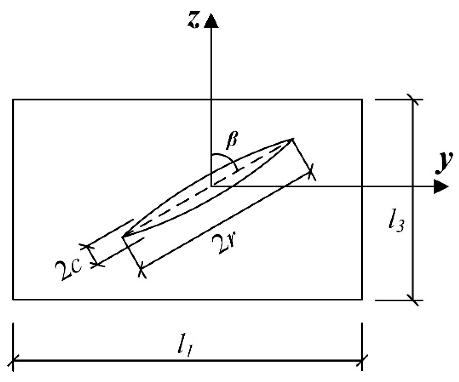
Figure 1. Schematic of a thin elliptical crack in the RVE unit.
Materials 17 02877 g001
Figure 2. The relationship between effective modulus and parameters p, β.
Materials 17 02877 g002
Figure 3. Variation curve of the effective modulus of asphalt concrete with crack density.
Materials 17 02877 g003
Figure 4. Sketch of interactions and the corresponding constitutive models within the digital sample of asphalt mixtures.
Materials 17 02877 g004
Figure 5. The mechanical properties tests.
Materials 17 02877 g005
Figure 6. Meso-structural model of asphalt concrete containing microcracks and a macrocrack. (Note: The black particles represent the internal aggregate of asphalt concrete, the red lines represent microcrack clusters, and the blue lines represent the macrocrack).
Materials 17 02877 g006
Figure 7. Schematic diagram of the SCB virtual test.
Materials 17 02877 g007
Figure 8. Results of the effect of microcracks on a macrocrack. (Note: The black particles represent the internal aggregate of asphalt concrete, the red lines represent microcrack clusters, the blue lines represent the macrocrack, and the orange lines represent the cracks after propagation).
Materials 17 02877 g008
Figure 9. Variation curve of effective modulus of asphalt concrete.
Materials 17 02877 g009
Figure 10. Stress–strain curves of asphalt concrete with main cracks under different microcrack population densities.
Materials 17 02877 g010
Figure 11. Rose diagram of the stress field in the vertical crack tip domain of the macrocrack in asphalt concrete. (Note: the red line represents the average tensile stress field, and the blue line represents the average shear stress field).
Materials 17 02877 g011
Figure 12. Stress field area ratio of asphalt concrete crack tip.
Materials 17 02877 g012
Table 1. Gradation of AC-13 asphalt concrete.
Mess size (mm)16.013.29.54.752.361.180.600.300.150.075
Pass rate (%)100.097.584.062.542.532.024.015.511.06.0
Table 2. Physical indicators of AC-13 asphalt concrete.
Oil–Stone Ratio (%)Gross Volumetric Density (g/cm3)Marshall Stability (kN)Porosity (%)Flow Value (mm)Void Filled with Asphalt VFA (%)Maximum Theoretical Density (g/cm3)
6.272.54712.482.14.3476.22.610
Table 3. The indirect test result of AC-13 asphalt concrete at −20 °C.
ItemsValues
Failure load (kN)35.91
Splitting strength (MPa)3.553
Failure tensile strain (με)0.0103
Destructive stiffness modules (MPa)596.85
Table 4. The dynamic modulus test result of AC-13 asphalt concrete at −20 °C.
Temperature (°C)Dynamic Modulus (MPa)
0.1 Hz0.5 Hz1 Hz5 Hz10 Hz25 Hz
−2020,97323,83524,93326,99127,71728,486
Table 5. Calculation parameters of AC-13 asphalt concrete with a parallel bond model at −20 °C.
Material Phase ClassCalculated Parameters
Coarse aggregateDynamic modulus (GPa)55.5
Tensile strength σ (MPa)27.6
Poisson’s ratio νs0.23
Normal stiffness kn (MPa)222
Tangential stiffness ks (MPa)90.24
Asphalt concreteVoid ratio (%)2
Particle density (kg/m3)2582
Asphalt mortar Inter-particle contact modulus Ec (GPa)0.832
Particle normal to tangential stiffness ratio kn/ks1
Parallel bond modulus Ec (GPa)0.596
Parallel bond normal to tangential stiffness ratio knc/ksc0.667/0.133
Inter-particle friction coefficient fs0.5
Average normal strength of parallel bond σc (MPa)3.553
Standard deviation of parallel bond normal strength (MPa)1
Average tangential strength of parallel bond τc (MPa)3.553
Standard deviation of parallel bond tangential strength (MPa)55.5
Table 6. Relevant parameters during crack propagation.
Crack Density Parameter f3Crack Incubation StageCrack Extension StageFracture Stage
Number of Cracks Time Step Log lgtNumber of Cracks 1Number of Cracks 2
014.39 330.224460.02
0.214.20 290.272420.05
0.414.04280.242180.06
0.614.01140.71440.04
0.813.81150.421640.06
113.65120.321360.04
Note: ∆1, ∆2 represent the time elapsed at the crack extension stage and fracture stage, respectively.
Disclaimer/Publisher’s Note: The statements, opinions and data contained in all publications are solely those of the individual author(s) and contributor(s) and not of MDPI and/or the editor(s). MDPI and/or the editor(s) disclaim responsibility for any injury to people or property resulting from any ideas, methods, instructions or products referred to in the content.