
Application of Li6.4La3Zr1.45Ta0.5Mo0.05O12/PEO Composite Solid Electrolyte in High-Performance Lithium Batteries

 and
and
Abstract
:1. Introduction
2. Experimental Methodology
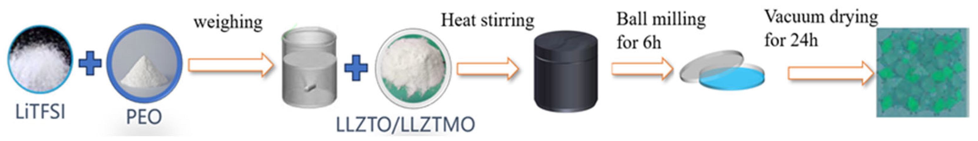
2.1. Synthesis of LLZTMO–PEO
2.2. Characterizations and Measurements
3. Results and Discussion
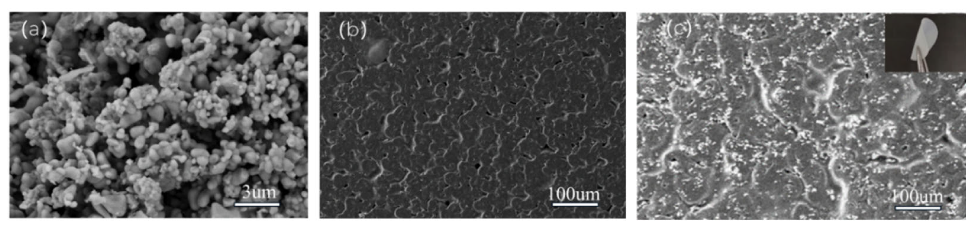
3.1. SEM
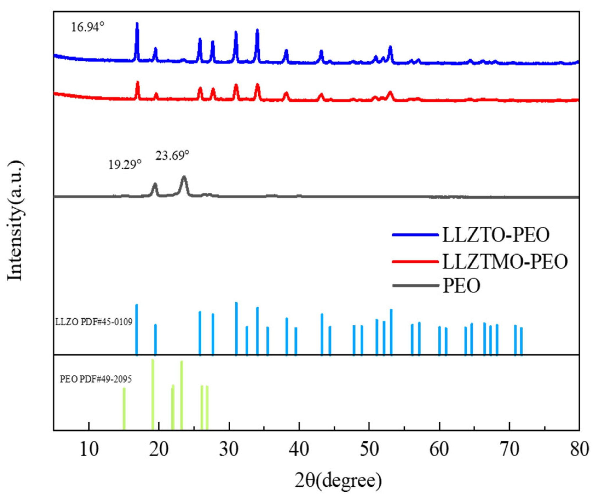
3.2. XRD
3.3. TGA
3.4. Ionic Conductivity and Activation Energy
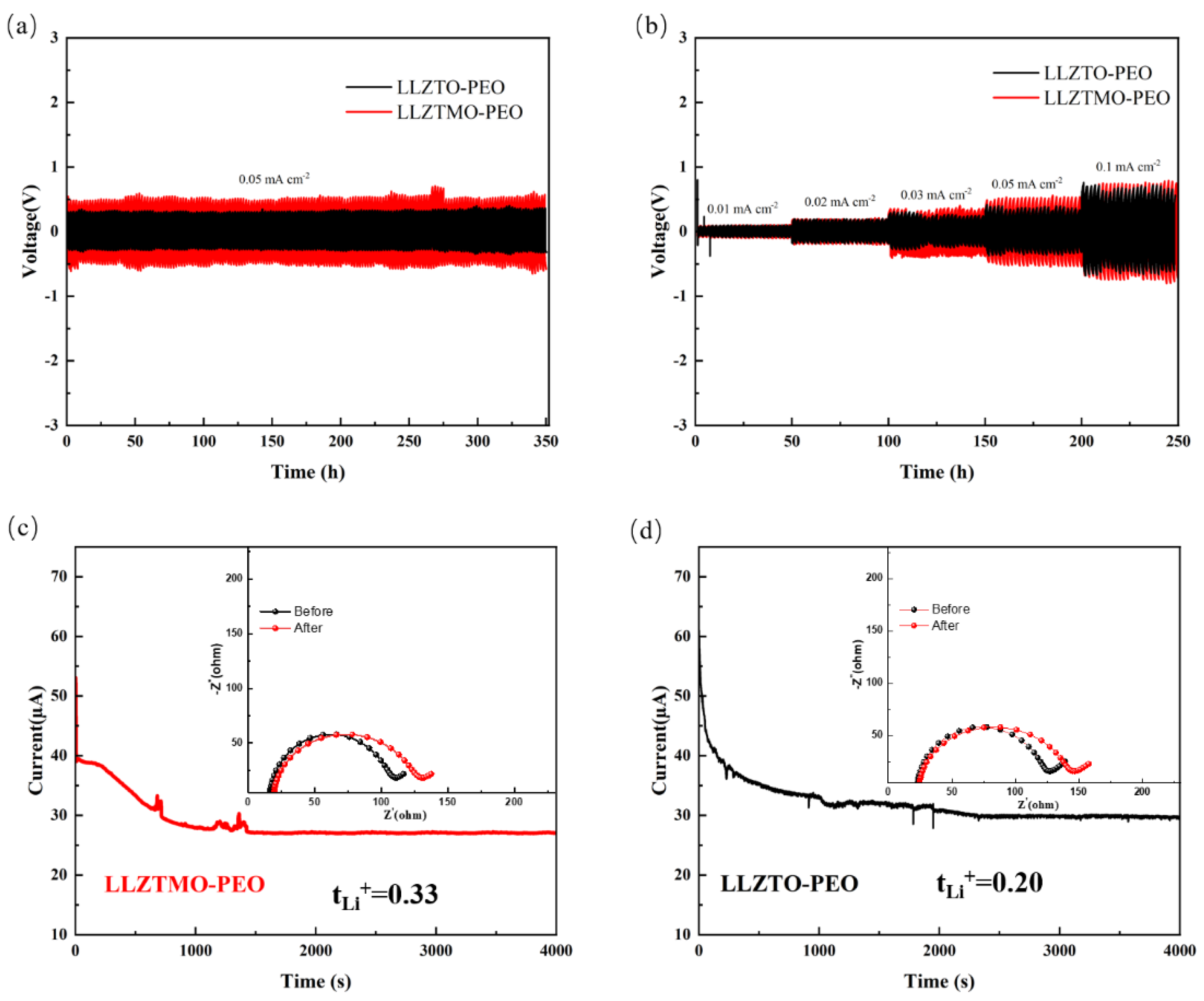
3.5. Lithium Compatibility Analysis
3.6. CV, LSV, and EIS
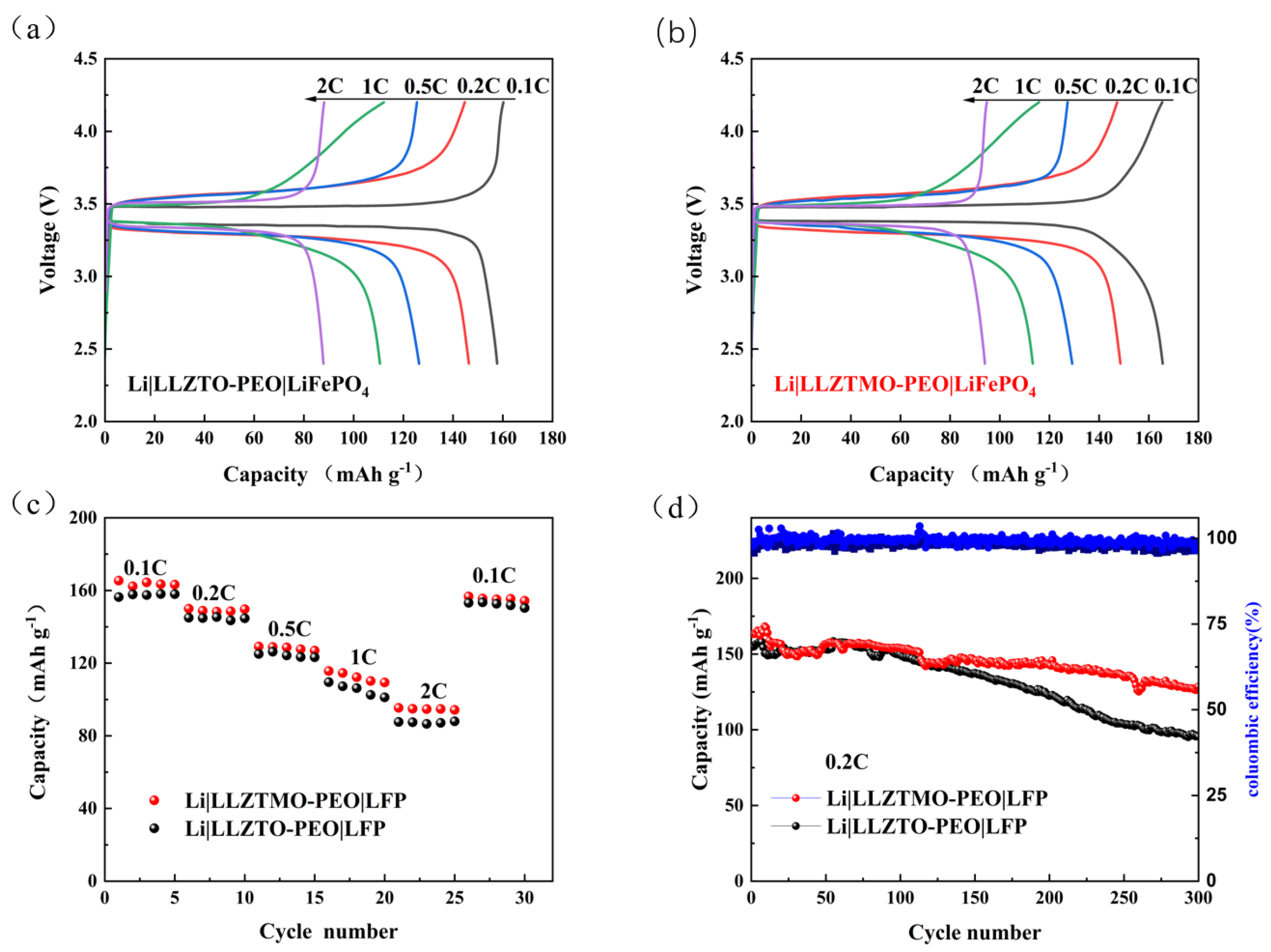
3.7. Electrochemical Performance of Li|LLZTMO/LLZTO–PEO|LiFePO4
4. Conclusions
Author Contributions
Funding
Institutional Review Board Statement
Informed Consent Statement
Data Availability Statement
Conflicts of Interest
References
- Schnell, J.; Knörzer, H.; Imbsweiler, A.J.; Reinhart, G. Solid versus Liquid-A Bottom-Up Calculation Model to Analyze the Manufacturing Cost of Future High-Energy Batteries. Energy Technol. 2020, 8, 1901237. [Google Scholar] [CrossRef]
- Hu, W.Q.; Zhang, C.H.; Jiang, H.; Zheng, M.S.; Wu, Q.H.; Dong, Q.F. Improving the electrochemistry performance of layed LiNi0.5Mn0.3Co0.2O2 material at 4.5 V cutoff potential using lithium metaborate. Electrochim. Acta 2017, 243, 105–111. [Google Scholar] [CrossRef]
- Chen, B.B.; Qian, H.; Xu, J.H.; Qin, L.L.; Wu, Q.H.; Zheng, M.S.; Dong, Q.F. Study on SnO2/graghene composites with superior electrochemical performance for lithium-ion batteries. J. Mater. Chem. A 2014, 2, 9345–9352. [Google Scholar] [CrossRef]
- Thangadurai, V.; Narayanan, S.; Pinzaru, D. Garnet-type solid-state fast Li ion conductors for Li batteries: Critical review. Chem. Soc. Rev. 2014, 43, 4714–4727. [Google Scholar] [CrossRef]
- Wang, W.W.; Gu, Y.; Yan, H.; Li, S.; He, J.W.; Xu, H.Y.; Wu, Q.H.; Yan, J.W.; Mao, B.W. Evaluating solid-electrolyte interphases for lithium and lithium-free anodes from nanoindentation features. Chem. 2020, 6, 2728–2745. [Google Scholar] [CrossRef]
- Tan, D.H.S.; Chen, Y.T.; Yang, H.; Bao, W.; Sreenarayanan, B.; Doux, J.M.; Li, W.; Lu, B.; Ham, S.Y.; Sayahpour, B. Carbon-free high-loading silicon anodes enabled by sulfide solid electrolytes. Science 2021, 373, 1494–1499. [Google Scholar] [CrossRef] [PubMed]
- Liu, X.Z.; Ding, L.; Liu, Y.Z.; Xiong, L.P.; Chen, J.; Luo, X.L. Room-temperature ionic conductivity of Ba, Y, Al co-doped Li7La3Zr2O12 solid electrolyte after sintering. Rare Met. 2021, 40, 2301–2306. [Google Scholar] [CrossRef]
- Kim, K.J.; Rupp, J.L.M. All ceramic cathode composite design and manufacturing towards low interfacial resistance for garnet-based solid-state lithium batteries. Energy Environ. Sci. 2020, 13, 4930–4945. [Google Scholar] [CrossRef]
- Sharafi, A.; Kazyak, E.; Davis, A.L.; Yu, S.; Thompson, T.; Siegel, D.J.; Dasgupta, N.P.; Sakamoto, J. Surface Chemistry Mechanism of Ultra-Low Interfacial Resistance in the Solid-State Electrolyte Li7La3Zr2O12. Chem. Mater. 2017, 29, 7961–7968. [Google Scholar] [CrossRef]
- Huang, Z.; Pang, W.; Liang, P.; Jin, Z.; Grundish, N.; Li, Y.; Wang, C.-A. A dopamine modified Li6.4La3Zr1.4Ta0.6O12/PEO solid-state electrolyte: Enhanced thermal and electrochemical properties. J. Mater. Chem. A 2019, 7, 16425–16436. [Google Scholar] [CrossRef]
- Fan, P.; Liu, H.; Marosz, V.; Samuels, N.T.; Suib, S.L.; Sun, L.; Liao, L. High Performance Composite Polymer Electrolytes for Lithium-Ion Batteries. Adv. Funct. Mater. 2021, 31, 2101380. [Google Scholar] [CrossRef]
- Zhang, J.; Zhao, N.; Zhang, M.; Li, Y.; Chu, P.K.; Guo, X.; Di, Z.; Wang, X.; Li, H. Flexible and ion-conducting membrane electrolytes for solid-state lithium batteries: Dispersion of garnet nanoparticles in insulating polyethylene oxide. Nano Energy 2016, 28, 447–454. [Google Scholar] [CrossRef]
- Lee, M.J.; Shin, D.O.; Kim, J.Y.; Oh, J.; Kang, S.H.; Kim, J.; Kim, K.M.; Lee, Y.M.; Kim, S.O.; Lee, Y.G. Interfacial barrier free organic-inorganic hybrid electrolytes for solid state batteries. Energy Storage Mater. 2021, 37, 306–314. [Google Scholar] [CrossRef]
- Kim, K.J.; Balaish, M.; Wadaguchi, M.; Kong, L.; Rupp, J.L.M. Solid-state Li–metal batteries: Challenges and horizons of oxide and sulfide solid electrolytes and their interfaces. Adv. Energy Mater. 2021, 11, 2002689. [Google Scholar] [CrossRef]
- Cho, J.H.; Kim, K.; Chakravarthy, S.; Xiao, X.; Rupp, J.L.M.; Sheldon, B.W. An Investigation of Chemo-Mechanical Phenomena and Li Metal Penetration in All-Solid-State Lithium Metal Batteries Using In Situ Optical Curvature Measurements. Adv. Energy Mater. 2022, 12, 2200369. [Google Scholar] [CrossRef]
- Lin, X.D.; Gu, Y.; Shen, X.R. An oxygen-blocking oriented multifunctional solid-electrolyte interphase as a protective layer for a lithium metal anode in lithium-oxygen batteries. Energy Environ. Sci. 2020, 14, 1439–1448. [Google Scholar]
- Boulineau, S.; Courty, M.; Tarascon, J.M. Mechanochemical synthesis of Li-argyrodite Li6PS5X (X = Cl, Br, I) as sulfur-based solid electrolytes for all solid state batteries application. Solid State Ionics 2012, 221, 1–5. [Google Scholar] [CrossRef]
- Schweiger, L.; Hogrefe, K.; Gadermaier, B. Ionic conductivity of nanocrystalline and amorphous Li10GeP2S12: The detrimental impact of local disorder on ion transport. J. Am. Chem. Soc. 2022, 144, 9597–9609. [Google Scholar] [CrossRef] [PubMed]
- Xu, H.; Yu, Y.; Wang, Z. First principle material genome approach for all solid-state batteries. Energy Environ. Mater. 2019, 2, 234–250. [Google Scholar] [CrossRef]
- Liu, Q.; Geng, Z.; Han, C. Challenges and perspectives of garnet solid electrolytes for all solid-state lithium batteries. J. Power Sources 2018, 389, 120–134. [Google Scholar] [CrossRef]
- Song, J.; Yang, X.; Zeng, S.S.; Cai, M.Z.; Zhang, L.T.; Dong, Q.F.; Zheng, M.S.; Wu, S.T.; Wu, Q.H. Solid-state microscale lithium batteries prepared with microfabrication process. J. Micromech. Microeng. 2009, 19, 045004. [Google Scholar] [CrossRef]
- Mahbub, R.; Huang, K.; Jensen, Z. Text mining for processing conditions of solid-state battery electrolytes. Electrochem. Commun. 2020, 121, 106860. [Google Scholar] [CrossRef]
- Tao, X.; Yang, L.; Liu, J. Preparation and performances of gallium-doped LLZO electrolyte with high ionic conductivity by rapid ultra-high-temperature sintering. J. Alloys Compd. 2023, 937, 168380. [Google Scholar] [CrossRef]
- Zhu, Y.; Kennedy, E.R.; Yasar, B. Uncovering the Network Modifier for Highly Disordered Amorphous Li-Garnet Glass-Ceramics. Adv. Mater. 2024, 36, 2302438. [Google Scholar] [CrossRef]
- Liu, X.; Garcia-Mendez, R.; Lupini, A.R. Local electronic structure variation resulting in Li ‘filament’formation within solid electrolytes. Nat. Mater. 2021, 20, 1485–1490. [Google Scholar] [CrossRef] [PubMed]
- Dixit, M.B.; Vishugopi, B.S.; Zaman, W. Polymorphism of garnet solid electrolytes and its implications for grain-level chemo-mechanics. Nat. Mater. 2022, 21, 1298–1305. [Google Scholar] [CrossRef]
- Zhu, Y.; Hood, Z.D.; Paik, H. Highly disordered amorphous Li-battery electrolytes. Matter 2024, 7, 500–522. [Google Scholar] [CrossRef]
- Sastre, J.; Futscher, M.H.; Pompizi, L. Blocking lithium dendrite growth in solid-state batteries with an ultrathin amorphous Li-La-Zr-O solid electrolyte. Commun. Mater. 2021, 2, 76. [Google Scholar] [CrossRef]
- Hood, Z.D.; Zhu, Y.; Miara, L.J. A sinter-free future for solid-state battery designs. Energy Environ. Sci. 2022, 15, 2927–2936. [Google Scholar] [CrossRef]
- Arinicheva, Y.; Guo, X.; Gerhards, M.T. Competing Effects in the Hydration Mechanism of a Garnet-Type Li7La3Zr2O12 Electrolyte. Chem. Mater. 2022, 34, 1473–1480. [Google Scholar] [CrossRef]
- Huo, H.; Luo, J.; Thangadurai, V. Li2CO3: A critical issue for develo** solid garnet batteries. ACS Energy Lett. 2020, 5, 252–262. [Google Scholar] [CrossRef]
- Sacci, R.L.; McAuliffe, R.D.; Malkowski, T.F. La2Zr2O7 nanoparticle-mediated synthesis of porous Al-doped Li7La3Zr2O12 garnet. Inorg. Chem. 2021, 60, 10012–10021. [Google Scholar] [CrossRef] [PubMed]
- Yastrebtsev, A.A.; Popov, V.V.; Menushenkov, A.P. Comparative neutron and X-ray diffraction analysis of anionic and cationic ordering in rare-earth zirconates (Ln = La, Nd, Tb, Yb, Y). J. Alloys Compd. 2020, 832, 154863. [Google Scholar] [CrossRef]
- Zhu, Y.; Gonzalez-Rosillo, J.C.; Balaish, M. Lithium-film ceramics for solid-state lithionic devices. Nat. Rev. Mater. 2021, 6, 313–331. [Google Scholar] [CrossRef]
- Wang, S.; Liu, Y.; Mo, Y. Frustration in Super-Ionic Conductors Unraveled by the Density of Atomistic States. Angew. Chem. Int. Ed. 2023, 135, e202215544. [Google Scholar] [CrossRef]
- Zhu, Y.; Chon, M.; Thompson, C.V. Time-Temperature-Transformation (TTT) Diagram of Battery-Grade Li-Garnet Electrolytes for Low-Temperature Sustainable Synthesis. Angew. Chem. Int. Ed. 2023, 135, e202304581. [Google Scholar] [CrossRef]
- Gao, Z.; Sun, H.; Fu, L.; Ye, F.; Zhang, Y.; Luo, W.; Huang, Y. All-solid-state batteries: Promises, challenges, and recent progress of inorganic solid-state electrolytes for all-solid-state lithium batteries. Adv. Mater. 2018, 30, 1870122. [Google Scholar] [CrossRef]
- Zhang, Y.; Gao, X.; Tang, Z. Study on the suppression lithium dendrites based on solid electrolyte Li7La3Zr2O12 with annealing treatment of Al interlayer. J. Alloys Compd. 2022, 904, 163908. [Google Scholar] [CrossRef]
- Koshikawa, H.; Matsuda, S.; Kamiya, K. Electrochemical impedance analysis of the Li/Au-Li7La3Zr2O12 interface during Li dissolution/deposition cycles: Effect of pre-coating Li7La3Zr2O12 with Au. J. Electroanal. Chem. 2019, 835, 143–149. [Google Scholar] [CrossRef]
- Wang, D.; Sun, Q.; Luo, J. Mitigating the interfacial degradation in cathodes for high-performance oxide-based solid-state lithium batteries. ACS Appl. Mater. Interfaces 2019, 11, 4954–4961. [Google Scholar] [CrossRef]
- Ihrig, M.; Finsterbusch, M.; Tsai, C.L. Low temperature sintering of fully inorganic all-solid-state batteries-Impact of interfaces on full cell performance. J. Power Sources 2021, 482, 228905. [Google Scholar] [CrossRef]
- Watanabe, K.; Tashiro, A.; Ichinose, Y. Lowering the sintering temperature of Li7La3Zr2O12 electrolyte for co-fired all-solid-state batteries via partial Bi substitution and precise control of compositional deviation. J. Ceram. Soc. Jpn. 2022, 130, 416–423. [Google Scholar] [CrossRef]
- Hayashi, N.; Watanabe, K.; Shimanoe, K. Low-temperature sintering characteristics and electrical properties of Ca-and Bi-doped Li7La3Zr2O12 electrolyte containing Li3BO3 additive. J. Mater. Chem. A 2023, 11, 2042–2053. [Google Scholar] [CrossRef]
- Hayashi, N.; Watanabe, K.; Ohnishi, T. Impact of intentional composition tuning on the sintering properties of Ca-Bi co-doped Li7La3Zr2O12 for co-fired solid-state batteries. J. Mater. Chem. A 2023, 11, 15681–15690. [Google Scholar] [CrossRef]
- Jiang, B.; Li, F.; Hou, T.; Liu, Y.; Cheng, H.; Li, D.; Xu, H.; Huang, Y. Polymer electrolytes shielded by 2D Li0.46Mn0.77PS3Li+-conductors for all-solid-state lithium-metal batteries. Energy Storage Mater. 2023, 56, 183–191. [Google Scholar] [CrossRef]
- Randau, S.; Weber, D.A.; Kötz, O. Benchmarking the performance of all-solid-state lithium batteries. Nat. Energy 2020, 5, 259–270. [Google Scholar] [CrossRef]
- Chen, L.; Huang, Z.; Pang, W. Dual interface layers for solid-state Li metal battery with low interfacial resistance and small polarization based on garnet electrolyte. Electrochim. Acta 2020, 330, 135352. [Google Scholar] [CrossRef]
- Huang, J.; Liang, F.; Hou, M. Garnet-type solid-state electrolytes and interfaces in all-solid-state lithium batteries: Progress and perspective. Appl. Mater. Today 2020, 20, 100750. [Google Scholar] [CrossRef]


| Rate C | Li|LLZTMO–PEO|LiFePO4 (mAh g−1) | Li|LLZTO–PEO|LiFePO4 (mAh g−1) |
|---|---|---|
| 0.1C | 165.4 | 156.4 |
| 0.2C | 149.9 | 144.9 |
| 0.5C | 129.1 | 125.0 |
| 1C | 115.6 | 109.5 |
| 2C | 94.3 | 87.6 |
| 0.1C | 156.7 | 150.4 |
Disclaimer/Publisher’s Note: The statements, opinions and data contained in all publications are solely those of the individual author(s) and contributor(s) and not of MDPI and/or the editor(s). MDPI and/or the editor(s) disclaim responsibility for any injury to people or property resulting from any ideas, methods, instructions or products referred to in the content. |
© 2024 by the authors. Licensee MDPI, Basel, Switzerland. This article is an open access article distributed under the terms and conditions of the Creative Commons Attribution (CC BY) license (https://creativecommons.org/licenses/by/4.0/).
Share and Cite
Lin, C.; Huang, Y.; Deng, D.; Xiong, H.; Lu, B.; Weng, J.; Fan, X.; Li, G.; Zeng, Y.; Li, Y.; et al. Application of Li6.4La3Zr1.45Ta0.5Mo0.05O12/PEO Composite Solid Electrolyte in High-Performance Lithium Batteries. Materials 2024, 17, 3094. https://doi.org/10.3390/ma17133094
Lin C, Huang Y, Deng D, Xiong H, Lu B, Weng J, Fan X, Li G, Zeng Y, Li Y, et al. Application of Li6.4La3Zr1.45Ta0.5Mo0.05O12/PEO Composite Solid Electrolyte in High-Performance Lithium Batteries. Materials. 2024; 17(13):3094. https://doi.org/10.3390/ma17133094
Chicago/Turabian StyleLin, Chengjun, Yaoyi Huang, Dingrong Deng, Haiji Xiong, Bin Lu, Jianchun Weng, Xiaohong Fan, Guifang Li, Ye Zeng, Yi Li, and et al. 2024. "Application of Li6.4La3Zr1.45Ta0.5Mo0.05O12/PEO Composite Solid Electrolyte in High-Performance Lithium Batteries" Materials 17, no. 13: 3094. https://doi.org/10.3390/ma17133094