

Advanced 3D Printing of Polyetherketoneketone Hydroxyapatite Composites via Fused Filament Fabrication with Increased Interlayer Connection

 ,
,  , ,
, , 
Abstract

1. Introduction
2. Experimental
2.1. Materials
2.2. Methods
3. Results and Discussion
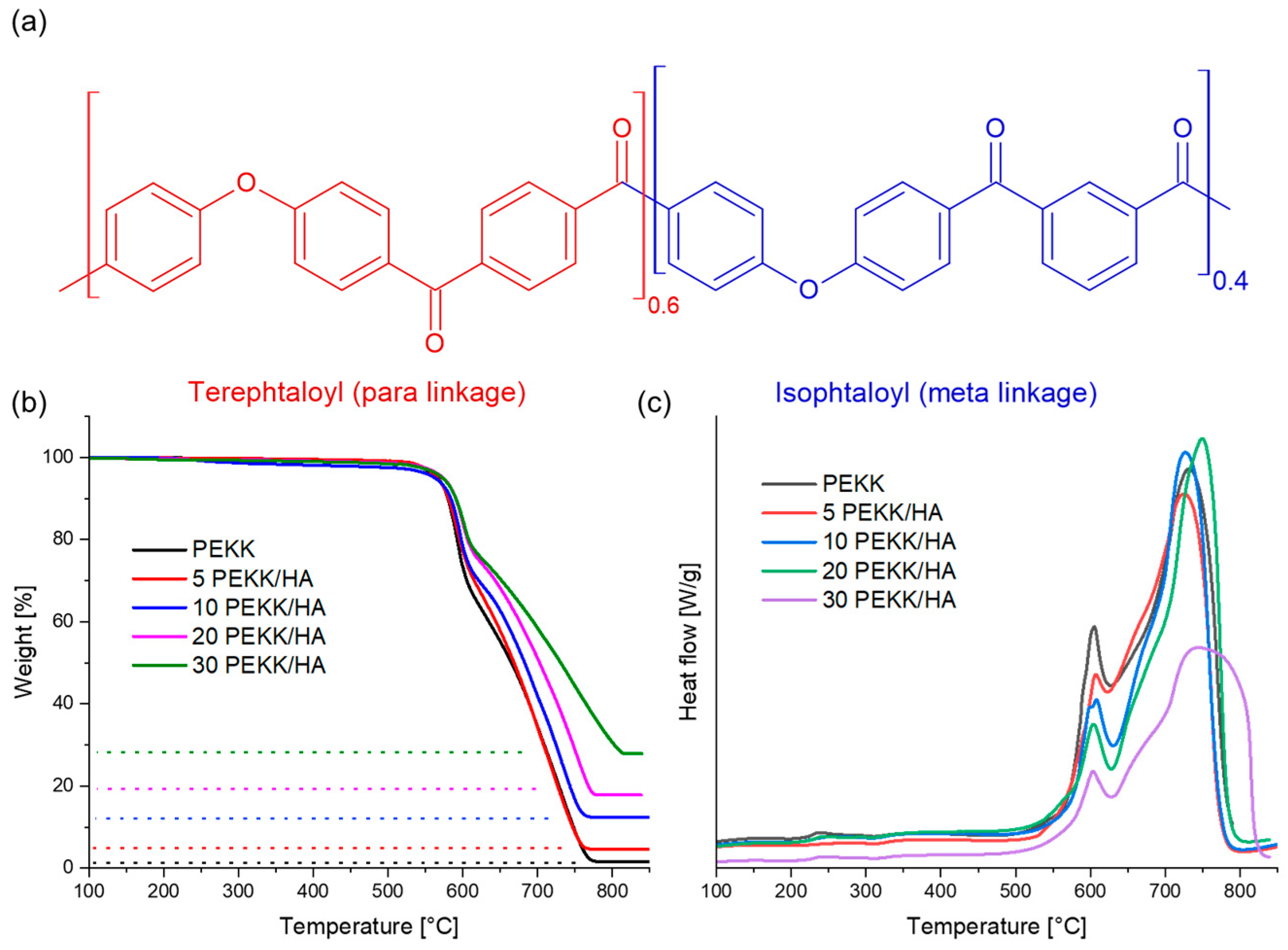
3.1. Thermal Stability
3.2. Thermal and Mechanical Behaviour
3.3. Morphology
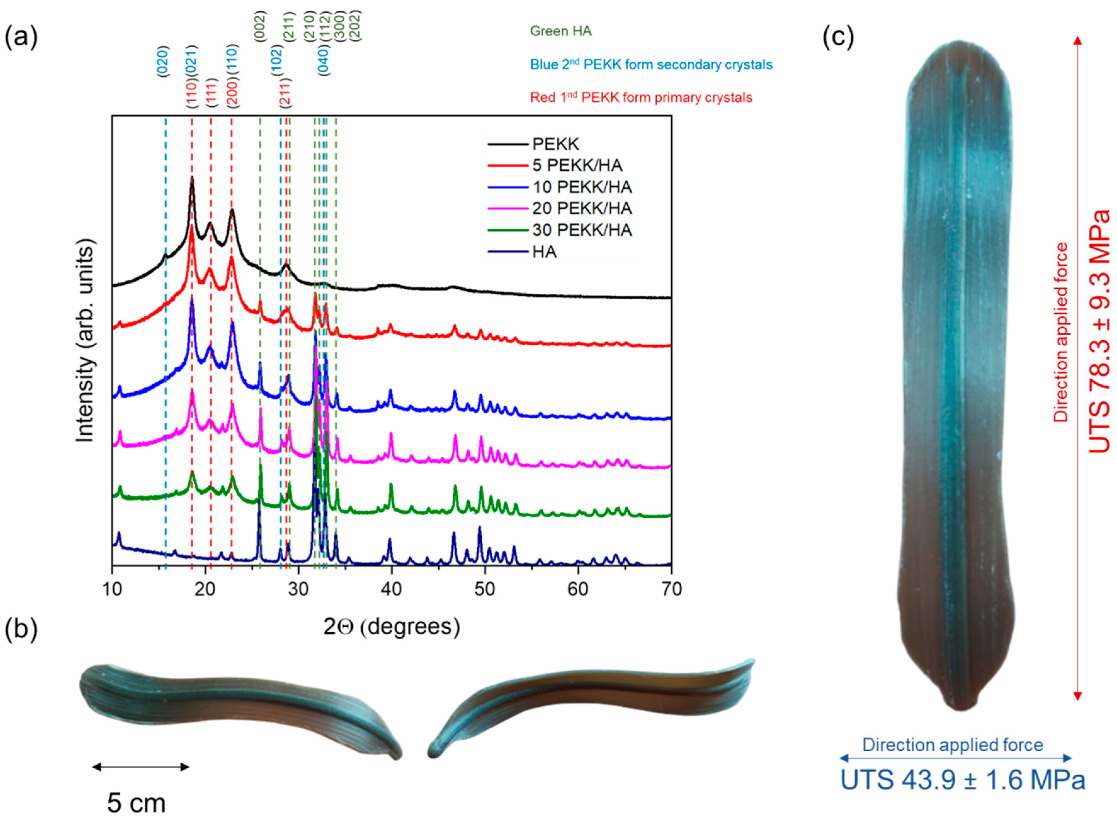
3.4. Crystallinity
4. Conclusions
Supplementary Materials
Author Contributions
Funding
Institutional Review Board Statement
Informed Consent Statement
Data Availability Statement
Conflicts of Interest
References
- Kantaros, A.; Ganetsos, T. From Static to Dynamic: Smart Materials Pioneering Additive Manufacturing in Regenerative Medicine. Int. J. Mol. Sci. 2023, 24, 15748. [Google Scholar] [CrossRef] [PubMed]
- Kantaros, A.; Ganetsos, T.; Petrescu, F.I.T. Transforming Object Design and Creation: Biomaterials and Contemporary Manufacturing Leading the Way. Biomimetics 2024, 9, 48. [Google Scholar] [CrossRef] [PubMed]
- Vaezi, M.; Yang, S. Extrusion-based additive manufacturing of PEEK for biomedical applications. Virtual Phys. Prototyp. 2015, 10, 123–135. [Google Scholar] [CrossRef]
- Pranzo, D.; Larizza, P.; Filippini, D.; Percoco, G. Extrusion-Based 3D Printing of Microfluidic Devices for Chemical and Biomedical Applications: A Topical Review. Micromachines 2018, 9, 374. [Google Scholar] [CrossRef] [PubMed]
- Singh, S.; Prakash, C.; Ramakrishna, S. 3D printing of polyether-ether-ketone for biomedical applications. Eur. Polym. J. 2019, 114, 234–248. [Google Scholar] [CrossRef]
- Pu’Ad, N.A.S.M.; Haq, R.H.A.; Noh, H.M.; Abdullah, H.Z.; Idris, M.I.; Lee, T.C. Review on the fabrication of fused deposition modelling (FDM) composite filament for biomedical applications. Mater. Today Proc. 2020, 29, 228–232. [Google Scholar] [CrossRef]
- Kökcü, I.; Eryildiz, M.; Altan, M.; Ertuğrul, M.; Odabaş, S. Scaffold fabrication from drug loaded HNT reinforced polylactic acid by FDM for biomedical applications. Polym. Compos. 2023, 44, 2138–2152. [Google Scholar] [CrossRef]
- Oladapo, B.I.; Zahedi, S.A.; Ismail, S.O.; Omigbodun, F.T. 3D printing of PEEK and its composite to increase biointerfaces as a biomedical material—A review. Colloids Surf. B Biointerfaces 2021, 203, 111726. [Google Scholar] [CrossRef] [PubMed]
- Kurtz, S.M.; Devine, J.N. PEEK biomaterials in trauma, orthopedic, and spinal implants. Biomaterials 2007, 28, 4845–4869. [Google Scholar] [CrossRef]
- Sikder, P.; Challa, B.T.; Gummadi, S.K. A comprehensive analysis on the processing-structure-property relationships of FDM-based 3-D printed polyetheretherketone (PEEK) structures. Materialia 2022, 22, 101427. [Google Scholar] [CrossRef]
- Rendas, P.; Figueiredo, L.; Geraldo, M.; Vidal, C.; Soares, B. Improvement of tensile and flexural properties of 3D printed PEEK through the increase of interfacial adhesion. J. Manuf. Process. 2023, 93, 260–274. [Google Scholar] [CrossRef]
- Arif, M.; Kumar, S.; Varadarajan, K.; Cantwell, W. Performance of biocompatible PEEK processed by fused deposition additive manufacturing. Mater. Des. 2018, 146, 249–259. [Google Scholar] [CrossRef]
- Rodzeń, K.; Harkin-Jones, E.; Wegrzyn, M.; Sharma, P.; Zhigunov, A. Improvement of the layer-layer adhesion in FFF 3D printed PEEK/carbon fibre composites. Compos. Part A Appl. Sci. Manuf. 2021, 149, 106532. [Google Scholar] [CrossRef]
- Xu, Q.; Xu, W.; Yang, Y.; Yin, X.; Zhou, C.; Han, J.; Li, X.; Shang, Y.; Zhang, H. Enhanced interlayer strength in 3D printed poly (ether ether ketone) parts. Addit. Manuf. 2022, 55, 102852. [Google Scholar] [CrossRef]
- Xu, Q.; Shang, Y.; Jiang, Z.; Wang, Z.; Zhou, C.; Liu, X.; Yan, Q.; Li, X.; Zhang, H. Effect of molecular weight on mechanical properties and microstructure of 3D printed poly(ether ether ketone). Polym. Int. 2020, 70, 1065–1072. [Google Scholar] [CrossRef]
- Paszkiewicz, S.; Lesiak, P.; Walkowiak, K.; Irska, I.; Miądlicki, K.; Królikowski, M.; Piesowicz, E.; Figiel, P. The Mechanical, Thermal, and Biological Properties of Materials Intended for Dental Implants: A Comparison of Three Types of Poly(aryl-ether-ketones) (PEEK and PEKK). Polymers 2023, 15, 3706. [Google Scholar] [CrossRef] [PubMed]
- Rodzeń, K.; Sharma, P.K.; McIlhagger, A.; Mokhtari, M.; Dave, F.; Tormey, D.; Sherlock, R.; Meenan, B.J.; Boyd, A. The Direct 3D Printing of Functional PEEK/Hydroxyapatite Composites via a Fused Filament Fabrication Approach. Polymers 2021, 13, 545. [Google Scholar] [CrossRef] [PubMed]
- Gohn, A.M.; Seo, J.; Colby, R.H.; Schaake, R.P.; Androsch, R.; Rhoades, A.M. Crystal nucleation in poly(ether ether ketone)/carbon nanotube nanocomposites at high and low supercooling of the melt. Polymer 2020, 199, 122548. [Google Scholar] [CrossRef]
- Seo, J.; Gohn, A.M.; Dubin, O.; Takahashi, H.; Hasegawa, H.; Sato, R.; Rhoades, A.M.; Schaake, R.P.; Colby, R.H. Isothermal crystallization of poly(ether ether ketone) with different molecular weights over a wide temperature range. Polym. Cryst. 2019, 2, 10055. [Google Scholar] [CrossRef]
- Tardif, X.; Pignon, B.; Boyard, N.; Schmelzer, J.W.; Sobotka, V.; Delaunay, D.; Schick, C. Experimental study of crystallization of PolyEtherEtherKetone (PEEK) over a large temperature range using a nano-calorimeter. Polym. Test. 2014, 36, 10–19. [Google Scholar] [CrossRef]
- Zheng, J.; Zhao, H.; Dong, E.; Kang, J.; Liu, C.; Sun, C.; Li, D.; Wang, L. Additively-manufactured PEEK/HA porous scaffolds with highly-controllable mechanical properties and excellent biocompatibility. Mater. Sci. Eng. C 2021, 128, 112333. [Google Scholar] [CrossRef] [PubMed]
- Vaezi, M.; Yang, S. A novel bioactive PEEK/HA composite with controlled 3D interconnected HA network. Int. J. Bioprint. 2015, 1, 66–76. [Google Scholar] [CrossRef]
- Gide, K.M.; Islam, S.; Bagheri, Z.S. Polymer-Based Materials Built with Additive Manufacturing Methods for Orthopedic Applications: A Review. J. Compos. Sci. 2022, 6, 262. [Google Scholar] [CrossRef]
- Pulipaka, A.; Gide, K.M.; Beheshti, A.; Bagheri, Z.S. Effect of 3D printing process parameters on surface and mechanical properties of FFF-printed PEEK. J. Manuf. Process. 2023, 85, 368–386. [Google Scholar] [CrossRef]
- Gardner, K.H.; Hsiao, B.S.; Faron, K.L. Polymorphism in poly(aryl ether ketone)s. Polymer 1994, 35, 2290–2295. [Google Scholar] [CrossRef]
- Ho, R.M.; Cheng, S.Z.D.; Hsiao, B.S.; Gardner, K.H. Isothermal melt and cold crystallization kinetics of poly(aryl ether ether ketone ketone) (PEEKK). Macromolecules 1994, 27, 2136. [Google Scholar] [CrossRef]
- Gardner, K.H.; Hsiao, B.S.; Matheson, R.R.; Wood, B.A. Structure, crystallization and morphology of poly (aryl ether ketone ketone). Polymer 1992, 33, 2483–2495. [Google Scholar] [CrossRef]
- Odrobina, M.; Deák, T.; Székely, L.; Mankovits, T.; Keresztes, R.Z.; Kalácska, G. The Effect of Crystallinity on the Toughness of Cast Polyamide 6 Rods with Different Diameters. Polymers 2020, 12, 293. [Google Scholar] [CrossRef] [PubMed]
- Bessell, T.J.; Hull, D.; Shortall, J.B. The effect of polymerization conditions and crystallinity on the mechanical properties and fracture of spherulitic nylon 6. J. Mater. Sci. 1975, 10, 1127–1136. [Google Scholar] [CrossRef]
- Rodzeń, K.; McIvor, M.J.; Sharma, P.K.; Acheson, J.G.; McIlhagger, A.; Mokhtari, M.; McFerran, A.; Ward, J.; Meenan, B.J.; Boyd, A.R. The Surface Characterisation of Fused Filament Fabricated (FFF) 3D Printed PEEK/Hydroxyapatite Composites. Polymers 2021, 13, 3117. [Google Scholar] [CrossRef]
- Lu, W.; Li, C.; Wu, J.; Ma, Z.; Zhang, Y.; Xin, T.; Liu, X.; Chen, S. Preparation and Characterization of a Polyetherketoneketone/Hydroxyapatite Hybrid for Dental Applications. J. Funct. Biomater. 2022, 13, 220. [Google Scholar] [CrossRef] [PubMed]
- Hu, X.; Mei, S.; Wang, F.; Qian, J.; Xie, D.; Zhao, J.; Yang, L.; Wu, Z.; Wei, J. Implantable PEKK/tantalum microparticles composite with improved surface performances for regulating cell behaviors, promoting bone formation and osseointegration. Bioact. Mater. 2021, 6, 928–940. [Google Scholar] [CrossRef]
- Wang, M.; Bhardwaj, G.; Webster, T.J. Antibacterial properties of PEKK for orthopedic applications. Int. J. Nanomed. 2023, 12, 6471–6476. [Google Scholar] [CrossRef] [PubMed]
- Rodzeń, K.; McIlhagger, A.; Strachota, B.; Strachota, A.; Meenan, B.J.; Boyd, A. Controlling Crystallization: A Key Factor during 3D Printing with the Advanced Semicrystalline Polymeric Materials PEEK, PEKK 6002, and PEKK 7002. Macromol. Mater. Eng. 2023, 308, 2200668. [Google Scholar] [CrossRef]
- Papageorgiou, D.G.; Roumeli, E.; Chrissafis, K.; Lioutas, C.; Triantafyllidis, K.; Bikiaris, D.; Boccaccini, A.R. Thermal degradation kinetics and decomposition mechanism of PBSu nanocomposites with silica-nanotubes and strontium hydroxyapatite nanorods. Phys. Chem. Chem. Phys. 2014, 16, 4830–4842. [Google Scholar] [CrossRef]
- Papageorgiou, G.Z.; Achilias, D.S.; Bikiaris, D.N.; Karayannidis, G.P. Crystallization kinetics and nucleation activity of filler in polypropylene/surface-treated SiO2 nanocomposites. Thermochim. Acta 2005, 427, 117–128. [Google Scholar] [CrossRef]
- Lanzl, L.; Wudy, K.; Greiner, S.; Drummer, D. Selective laser sintering of copper filled polyamide 12: Characterization of powder properties and process behavior. Polym. Compos. 2018, 40, 1801–1809. [Google Scholar] [CrossRef]
- Garcia-Leiner, M.; Streifel, B.; Başgül, C.; MacDonald, D.W.; Kurtz, S.M. Characterization of polyaryletherketone (PAEK) filaments and printed parts produced by extrusion-based additive manufacturing. Polym. Int. 2021, 70, 1128–1136. [Google Scholar] [CrossRef]
- Amaral, M.; Lopes, M.; Silva, R.; Santos, J. Densification route and mechanical properties of Si3N4–bioglass biocomposites. Biomaterials 2002, 23, 857–862. [Google Scholar] [CrossRef]
- Ouchiar, S.; Stoclet, G.; Cabaret, C.; Gloaguen, V. Influence of the Filler Nature on the Crystalline Structure of Polylactide-Based Nanocomposites: New Insights into the Nucleating Effect. Macromolecules 2016, 49, 2782–2790. [Google Scholar] [CrossRef]
- Magri, A.E.; Vaudreuil, S.; Ayad, A.B.; El Hakimi, A.; Otmani, R.E.; Amegouz, D. Effect of printing parameters on tensile, thermal and structural properties of 3D-printed poly (ether ketone ketone) PEKK material using fused deposition modeling. J. Appl. Polym. Sci. 2023, 140, 54078. [Google Scholar] [CrossRef]
- Gao, S.-L.; Kim, J.-K. Cooling rate influences in carbon fibre/PEEK composites. Part 1. Crystallinity and interface adhesion. Compos. Part A Appl. Sci. Manuf. 2000, 31, 517–530. [Google Scholar] [CrossRef]
- Veazey, D.; Hsu, T.; Gomez, E.D. Enhancing resistance of poly(ether ketone ketone) to high-temperature steam through crosslinking and crystallization control. J. Appl. Polym. Sci. 2019, 136, 47727. [Google Scholar] [CrossRef]
- Wu, W.; Xin, J.; Hu, B.; Chen, R.; Huang, D.; Huang, Z.; Feng, J.; Du, C.; Shan, B. Achieving injection molding interlayer strength via powder assisted hot isostatic pressing in material extrusion polyetheretherketone. Addit. Manuf. 2023, 74, 103735. [Google Scholar] [CrossRef]
- Collinson, D.W.; von Windheim, N.; Gall, K.; Brinson, L.C. Direct evidence of interfacial crystallization preventing weld formation during fused filament fabrication of poly(ether ether ketone). Addit. Manuf. 2022, 51, 102604. [Google Scholar] [CrossRef]


| Z Printing Direction | PEKK | 5 PEKK/HA | 10 PEKK/HA | 20 PEKK/HA | 30 PEKK/HA |
|---|---|---|---|---|---|
| Modulus [MPa] | 304 ± 55 | 374 ± 61 | 432 ± 63 | 396 ± 50 | 392 ± 66 |
| UTS [MPa] | 28.2 ± 7.0 | 35.5 ± 2.9 | 43.9 ± 1.6 | 30.0 ± 6.1 | 17.4 ± 3.9 |
| Strain [%] | 11.9 ± 3.0 | 11.5 ± 1.7 | 13.4 ± 1.7 | 8.7 ± 1.9 | 6.0 ± 2.9 |
| XY Printing Direction | |||||
| Modulus [MPa] | 1059 ± 125 | 1202 ± 33 | 1346 ± 136 | 1434 ± 47 | 1602 ± 127 |
| UTS [MPa] | 83.4 ± 12.0 | 80.5 ± 6.9 | 78.3 ± 9.3 | 79.8 ± 11.2 | 58.9 ± 7.9 |
| Strain [%] | 11.8 ± 2.2 | 8.1 ± 0.7 | 7.1 ± 1.5 | 6.6 ± 1.1 | 4.4 ± 0.6 |
| XcXRD [%] | 13.1 | 14.4 | 12.5 | 10.6 | 8.3 |
| Grain Size [nm] | 14.8 | 14.7 | 14.3 | 15.0 | 14.7 |
Disclaimer/Publisher’s Note: The statements, opinions and data contained in all publications are solely those of the individual author(s) and contributor(s) and not of MDPI and/or the editor(s). MDPI and/or the editor(s) disclaim responsibility for any injury to people or property resulting from any ideas, methods, instructions or products referred to in the content. |
© 2024 by the authors. Licensee MDPI, Basel, Switzerland. This article is an open access article distributed under the terms and conditions of the Creative Commons Attribution (CC BY) license (https://creativecommons.org/licenses/by/4.0/).
Share and Cite
Rodzeń, K.; O’Donnell, E.; Hasson, F.; McIlhagger, A.; Meenan, B.J.; Ullah, J.; Strachota, B.; Strachota, A.; Duffy, S.; Boyd, A. Advanced 3D Printing of Polyetherketoneketone Hydroxyapatite Composites via Fused Filament Fabrication with Increased Interlayer Connection. Materials 2024, 17, 3161. https://doi.org/10.3390/ma17133161
Rodzeń K, O’Donnell E, Hasson F, McIlhagger A, Meenan BJ, Ullah J, Strachota B, Strachota A, Duffy S, Boyd A. Advanced 3D Printing of Polyetherketoneketone Hydroxyapatite Composites via Fused Filament Fabrication with Increased Interlayer Connection. Materials. 2024; 17(13):3161. https://doi.org/10.3390/ma17133161
Chicago/Turabian StyleRodzeń, Krzysztof, Eiméar O’Donnell, Frances Hasson, Alistair McIlhagger, Brian J. Meenan, Jawad Ullah, Beata Strachota, Adam Strachota, Sean Duffy, and Adrian Boyd. 2024. "Advanced 3D Printing of Polyetherketoneketone Hydroxyapatite Composites via Fused Filament Fabrication with Increased Interlayer Connection" Materials 17, no. 13: 3161. https://doi.org/10.3390/ma17133161
APA StyleRodzeń, K., O’Donnell, E., Hasson, F., McIlhagger, A., Meenan, B. J., Ullah, J., Strachota, B., Strachota, A., Duffy, S., & Boyd, A. (2024). Advanced 3D Printing of Polyetherketoneketone Hydroxyapatite Composites via Fused Filament Fabrication with Increased Interlayer Connection. Materials, 17(13), 3161. https://doi.org/10.3390/ma17133161