
Artificial Neural Network Prediction of Compliance Coefficients for Composite Shear Keys of Built-Up Timber Beams


Abstract
:1. Introduction
- Reinforcing elements (such as metal bolts) [12].
2. Materials and Methods
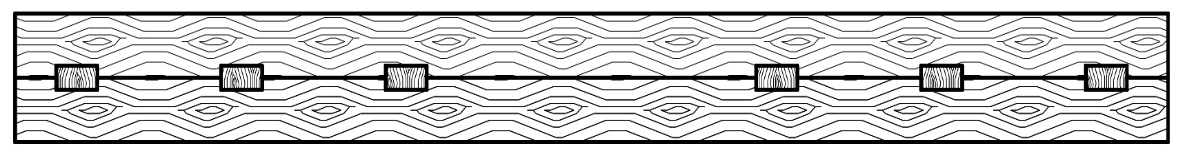
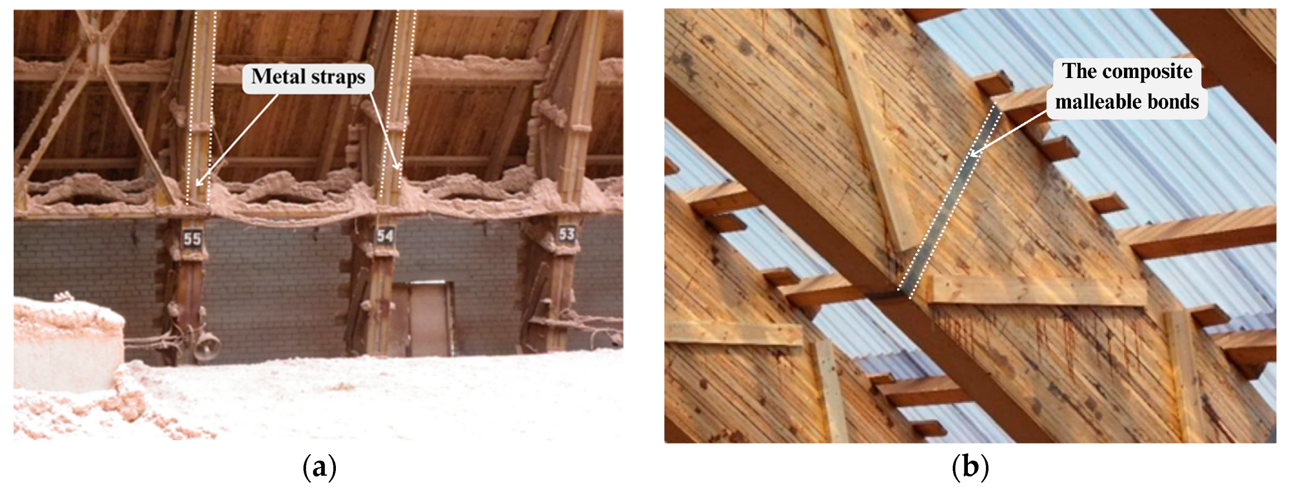
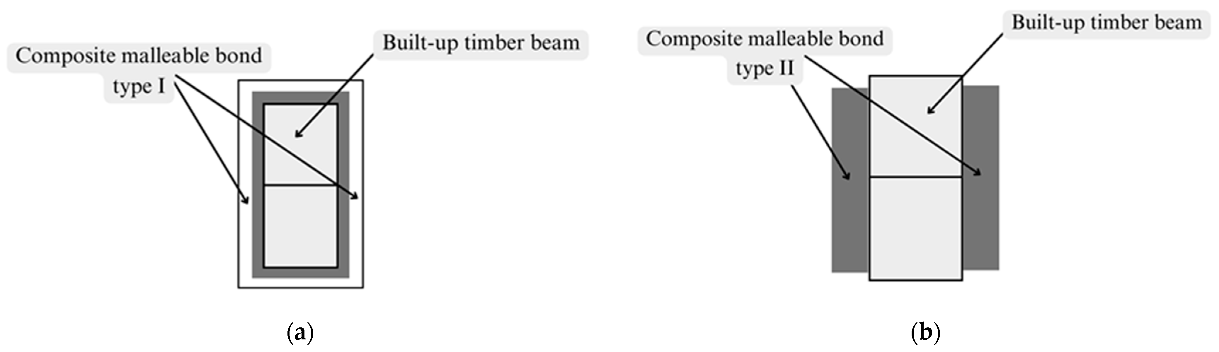
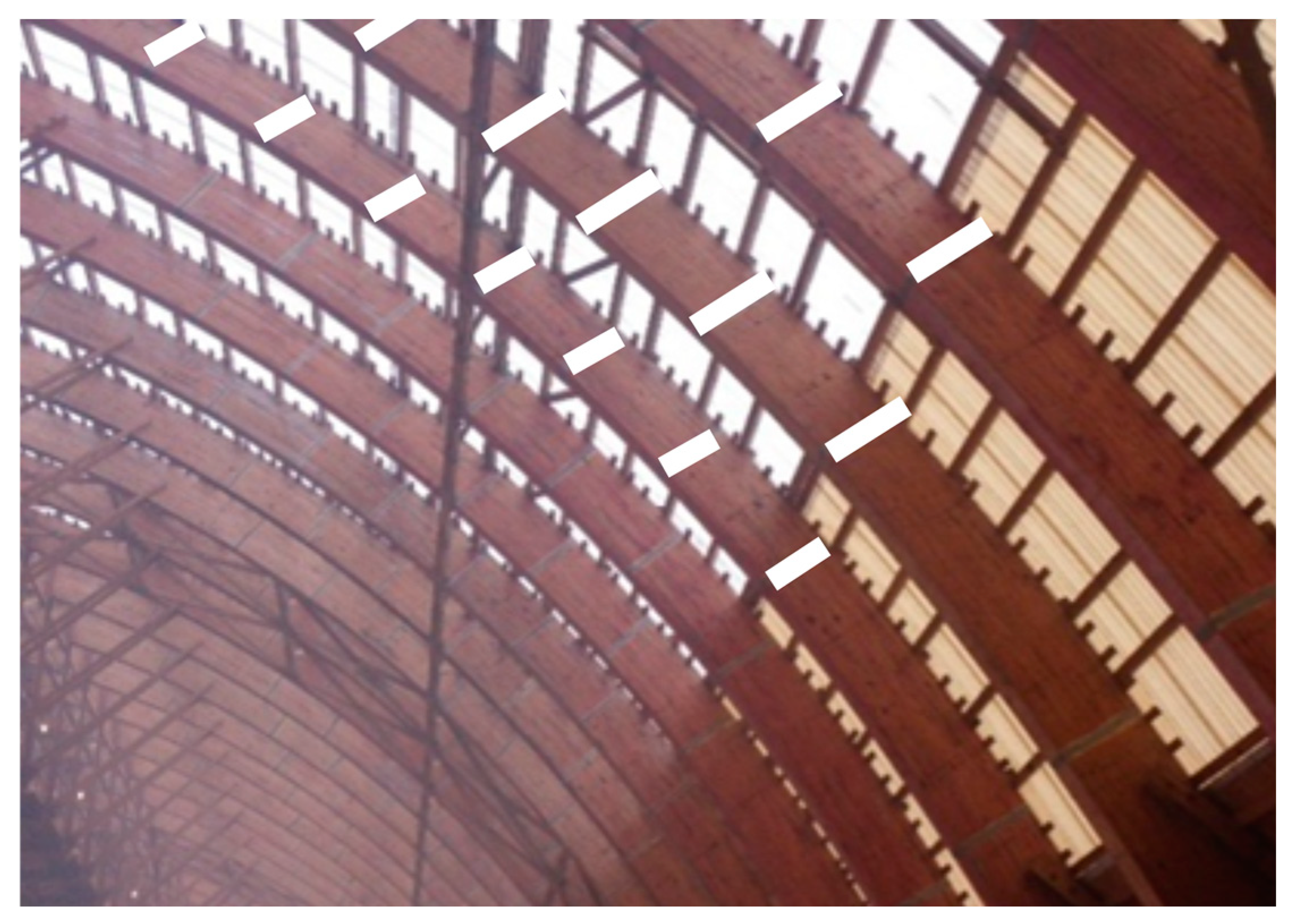
2.1. Overview of Built-Up Timber Beam with Mechanical Malleable Bonds Made of Composite Materials Design
2.2. The Collected Data of Compliance Coefficient
- Mechanical characteristics of the composite material from which the mechanical malleable bonds are made, such as fiberglass and glue. This parameter considers the bond’s material itself (unidirectional carbon fiber tape or fiberglass), as well as the glue that is used to glue the connection to the wood surface.
- The reinforcement coefficient.
- The thickness of the glued composite material and epoxy tape after drying.
- The number of tape layers.
- Lengths of the built-up timber beam.
- The number of layers in the built-up timber beam.
- The type of malleable bond (I or II).
- The load at the elastic limit on the load-strain curve for the two-cut sample.
- The strain at the elastic limit on the load-strain curve for the two-cut sample.
- The reinforcement coefficient for two cut samples.
- The reinforcement coefficient for built-up timber elements.
- The number of bonded details by the height of the cross-section for built-up timber elements.
- The reinforcement coefficient and the length of the built-up timber element.
- Length of the built-up timber element.
2.3. Application of Artificial Neural Network in Building Materials Research
3. Results
3.1. Essentials
- the type of connection,
- the load at the elastic limit on the stress–strain curve for the two-cut sample,
- the strain at the elastic limit on the stress–strain curve for the two-cut sample,
- the reinforcement coefficient for two-cut samples,
- the reinforcement coefficient for built-up timber elements,
- the number of bonded details by the height of the cross-section for built-up timber elements,
- the length of the built-up timber element.
3.2. Creating a Database for Predicting the Compliance Coefficients and
- is an -th element of an input type before standardization
- is the maximum value of an input type
- is an -th element of an input type after standardization
3.3. Results
- is the number of cases in the subset
- is the -th predicted value
- is the -th observed value
4. Discussion
- -
- Type 1 and Type 2 (described in earlier sections)
- -
- Joining the pinwood beams
- -
- Where inputs to ANN are within the existing ranges specified in Appendix A, Table A1 and Table A2 (e.g., max number of wooden layers is 10; max beam length is 6 m)
Author Contributions
Funding
Institutional Review Board Statement
Informed Consent Statement
Data Availability Statement
Conflicts of Interest
Appendix A

| Input Data | Output Data | |||||
|---|---|---|---|---|---|---|
| The Type of Connection | The Load at the Elastic Limit on the Stress-Strain Curve for Two-Cut Sample | The Reinforcement Coefficient for Two Cut Samples | Number of Wooden Layers in a Built-Up Timber Element | Reinforcement Coefficient for a Built-Up Timber Element | Length of the Timber Element, m | Compliance Coefficient |
| Type 1 | 5.983 | 0.375 | 2 | 0.25 | 3 | 0.88 |
| Type 1 | 5.983 | 0.375 | 3 | 0.25 | 3 | 0.78 |
| Type 1 | 5.983 | 0.375 | 10 | 0.25 | 3 | 0.70 |
| Type 1 | 5.983 | 0.375 | 2 | 0.3 | 3 | 0.92 |
| Type 1 | 5.983 | 0.375 | 3 | 0.3 | 3 | 0.80 |
| Type 1 | 5.983 | 0.375 | 10 | 0.3 | 3 | 0.74 |
| Type 1 | 5.983 | 0.375 | 2 | 0.5 | 3 | 0.94 |
| Type 1 | 5.983 | 0.375 | 3 | 0.5 | 3 | 0.82 |
| Type 1 | 5.983 | 0.375 | 10 | 0.5 | 3 | 0.76 |
| Type 1 | 5.983 | 0.375 | 2 | 0.7 | 3 | 0.95 |
| Type 1 | 5.983 | 0.375 | 3 | 0.7 | 3 | 0.84 |
| Type 1 | 5.983 | 0.375 | 10 | 0.7 | 3 | 0.78 |
| Type 1 | 5.983 | 0.375 | 2 | 1 | 3 | 0.96 |
| Type 1 | 5.983 | 0.375 | 3 | 1 | 3 | 0.86 |
| Type 1 | 5.983 | 0.375 | 10 | 1 | 3 | 0.80 |
| Type 1 | 5.983 | 0.375 | 2 | 0.25 | 4 | 0.90 |
| Type 1 | 5.983 | 0.375 | 3 | 0.25 | 4 | 0.84 |
| Type 1 | 5.983 | 0.375 | 10 | 0.25 | 4 | 0.76 |
| Type 1 | 5.983 | 0.375 | 2 | 0.3 | 4 | 0.92 |
| Type 1 | 5.983 | 0.375 | 3 | 0.3 | 4 | 0.86 |
| Type 1 | 5.983 | 0.375 | 10 | 0.3 | 4 | 0.78 |
| Type 1 | 5.983 | 0.375 | 2 | 0.5 | 4 | 0.94 |
| Type 1 | 5.983 | 0.375 | 3 | 0.5 | 4 | 0.88 |
| Type 1 | 5.983 | 0.375 | 10 | 0.5 | 4 | 0.80 |
| Type 1 | 5.983 | 0.375 | 2 | 0.7 | 4 | 0.95 |
| Type 1 | 5.983 | 0.375 | 3 | 0.7 | 4 | 0.90 |
| Type 1 | 5.983 | 0.375 | 10 | 0.7 | 4 | 0.82 |
| Type 1 | 5.983 | 0.375 | 2 | 1 | 4 | 0.96 |
| Type 1 | 5.983 | 0.375 | 3 | 1 | 4 | 0.92 |
| Type 1 | 5.983 | 0.375 | 10 | 1 | 4 | 0.84 |
| Type 1 | 5.983 | 0.375 | 2 | 0.25 | 6 | 0.92 |
| Type 1 | 5.983 | 0.375 | 3 | 0.25 | 6 | 0.88 |
| Type 1 | 5.983 | 0.375 | 10 | 0.25 | 6 | 0.80 |
| Type 1 | 5.983 | 0.375 | 2 | 0.3 | 6 | 0.93 |
| Type 1 | 5.983 | 0.375 | 3 | 0.3 | 6 | 0.92 |
| Type 1 | 5.983 | 0.375 | 10 | 0.3 | 6 | 0.82 |
| Type 1 | 5.983 | 0.375 | 2 | 0.5 | 6 | 0.94 |
| Type 1 | 5.983 | 0.375 | 3 | 0.5 | 6 | 0.94 |
| Type 1 | 5.983 | 0.375 | 10 | 0.5 | 6 | 0.84 |
| Type 1 | 5.983 | 0.375 | 2 | 0.7 | 6 | 0.95 |
| Type 1 | 5.983 | 0.375 | 3 | 0.7 | 6 | 0.95 |
| Type 1 | 5.983 | 0.375 | 10 | 0.7 | 6 | 0.86 |
| Type 1 | 5.983 | 0.375 | 2 | 1 | 6 | 0.96 |
| Type 1 | 5.983 | 0.375 | 3 | 1 | 6 | 0.96 |
| Type 1 | 5.983 | 0.375 | 10 | 1 | 6 | 0.88 |
| Type 1 | 12.659 | 0.75 | 2 | 0.25 | 3 | 0.88 |
| Type 1 | 12.659 | 0.75 | 3 | 0.25 | 3 | 0.78 |
| Type 1 | 12.659 | 0.75 | 10 | 0.25 | 3 | 0.70 |
| Type 1 | 12.659 | 0.75 | 2 | 0.3 | 3 | 0.92 |
| Type 1 | 12.659 | 0.75 | 3 | 0.3 | 3 | 0.80 |
| Type 1 | 12.659 | 0.75 | 10 | 0.3 | 3 | 0.74 |
| Type 1 | 12.659 | 0.75 | 2 | 0.5 | 3 | 0.94 |
| Type 1 | 12.659 | 0.75 | 3 | 0.5 | 3 | 0.82 |
| Type 1 | 12.659 | 0.75 | 10 | 0.5 | 3 | 0.76 |
| Type 1 | 12.659 | 0.75 | 2 | 0.7 | 3 | 0.95 |
| Type 1 | 12.659 | 0.75 | 3 | 0.7 | 3 | 0.84 |
| Type 1 | 12.659 | 0.75 | 10 | 0.7 | 3 | 0.78 |
| Type 1 | 12.659 | 0.75 | 2 | 1 | 3 | 0.96 |
| Type 1 | 12.659 | 0.75 | 3 | 1 | 3 | 0.86 |
| Type 1 | 12.659 | 0.75 | 10 | 1 | 3 | 0.80 |
| Type 1 | 12.659 | 0.75 | 2 | 0.25 | 4 | 0.90 |
| Type 1 | 12.659 | 0.75 | 3 | 0.25 | 4 | 0.84 |
| Type 1 | 12.659 | 0.75 | 10 | 0.25 | 4 | 0.76 |
| Type 1 | 12.659 | 0.75 | 2 | 0.3 | 4 | 0.92 |
| Type 1 | 12.659 | 0.75 | 3 | 0.3 | 4 | 0.86 |
| Type 1 | 12.659 | 0.75 | 10 | 0.3 | 4 | 0.78 |
| Type 1 | 12.659 | 0.75 | 2 | 0.5 | 4 | 0.94 |
| Type 1 | 12.659 | 0.75 | 3 | 0.5 | 4 | 0.88 |
| Type 1 | 12.659 | 0.75 | 10 | 0.5 | 4 | 0.80 |
| Type 1 | 12.659 | 0.75 | 2 | 0.7 | 4 | 0.95 |
| Type 1 | 12.659 | 0.75 | 3 | 0.7 | 4 | 0.90 |
| Type 1 | 12.659 | 0.75 | 10 | 0.7 | 4 | 0.82 |
| Type 1 | 12.659 | 0.75 | 2 | 1 | 4 | 0.96 |
| Type 1 | 12.659 | 0.75 | 3 | 1 | 4 | 0.92 |
| Type 1 | 12.659 | 0.75 | 10 | 1 | 4 | 0.84 |
| Type 1 | 12.659 | 0.75 | 2 | 0.25 | 6 | 0.92 |
| Type 1 | 12.659 | 0.75 | 3 | 0.25 | 6 | 0.88 |
| Type 1 | 12.659 | 0.75 | 10 | 0.25 | 6 | 0.80 |
| Type 1 | 12.659 | 0.75 | 2 | 0.3 | 6 | 0.93 |
| Type 1 | 12.659 | 0.75 | 3 | 0.3 | 6 | 0.92 |
| Type 1 | 12.659 | 0.75 | 10 | 0.3 | 6 | 0.82 |
| Type 1 | 12.659 | 0.75 | 2 | 0.5 | 6 | 0.94 |
| Type 1 | 12.659 | 0.75 | 3 | 0.5 | 6 | 0.94 |
| Type 1 | 12.659 | 0.75 | 10 | 0.5 | 6 | 0.84 |
| Type 1 | 12.659 | 0.75 | 2 | 0.7 | 6 | 0.95 |
| Type 1 | 12.659 | 0.75 | 3 | 0.7 | 6 | 0.95 |
| Type 1 | 12.659 | 0.75 | 10 | 0.7 | 6 | 0.86 |
| Type 1 | 12.659 | 0.75 | 2 | 1 | 6 | 0.96 |
| Type 1 | 12.659 | 0.75 | 3 | 1 | 6 | 0.96 |
| Type 1 | 12.659 | 0.75 | 10 | 1 | 6 | 0.88 |
| Type 2 | 19.000 | 1 | 2 | 1 | 1 | 0.90 |
| Type 2 | 19.000 | 1 | 2 | 1 | 3 | 0.95 |
| Type 2 | 19.000 | 1 | 2 | 1 | 6 | 0.95 |
| Type 2 | 16.000 | 1 | 2 | 1 | 1 | 0.90 |
| Type 2 | 16.000 | 1 | 2 | 1 | 3 | 0.95 |
| Type 2 | 16.000 | 1 | 2 | 1 | 6 | 0.95 |
| Type 2 | 16.000 | 1 | 2 | 1 | 1 | 0.90 |
| Type 2 | 16.000 | 1 | 2 | 1 | 3 | 0.95 |
| Type 2 | 16.000 | 1 | 2 | 1 | 6 | 0.95 |
| Type 2 | 19.000 | 1 | 2 | 1 | 1 | 0.90 |
| Type 2 | 19.000 | 1 | 2 | 1 | 3 | 0.95 |
| Type 2 | 19.000 | 1 | 2 | 1 | 6 | 0.95 |
| Type 2 | 22.000 | 1 | 2 | 1 | 1 | 0.90 |
| Type 2 | 22.000 | 1 | 2 | 1 | 3 | 0.95 |
| Type 2 | 22.000 | 1 | 2 | 1 | 6 | 0.95 |
| Type 2 | 19.000 | 1 | 2 | 1 | 1 | 0.90 |
| Type 2 | 19.000 | 1 | 2 | 1 | 3 | 0.95 |
| Type 2 | 19.000 | 1 | 2 | 1 | 6 | 0.95 |
| Type 2 | 25.000 | 1 | 2 | 1 | 3 | 0.95 |
| Type 2 | 25.000 | 1 | 2 | 1 | 6 | 0.95 |
| Type 2 | 25.000 | 1 | 2 | 1 | 1 | 0.90 |
| Type 2 | 22.000 | 1 | 2 | 1 | 3 | 0.95 |
| Type 2 | 22.000 | 1 | 2 | 1 | 6 | 0.95 |
| Type 2 | 22.000 | 1 | 2 | 1 | 1 | 0.90 |
| Type 2 | 22.000 | 1 | 2 | 1 | 3 | 0.95 |
| Type 2 | 22.000 | 1 | 2 | 1 | 6 | 0.95 |
| Type 2 | 13.000 | 1 | 2 | 1 | 3 | 0.95 |
| Type 2 | 13.000 | 1 | 2 | 1 | 6 | 0.95 |
| Type 2 | 13.000 | 1 | 2 | 1 | 1 | 0.90 |
| Type 2 | 16.000 | 1 | 2 | 1 | 3 | 0.95 |
| Type 2 | 16.000 | 1 | 2 | 1 | 6 | 0.95 |
| Type 2 | 16.000 | 1 | 2 | 1 | 1 | 0.90 |
| Type 2 | 16.000 | 1 | 2 | 1 | 3 | 0.95 |
| Type 2 | 16.000 | 1 | 2 | 1 | 6 | 0.95 |
| Input Data | Output Data | |||||
|---|---|---|---|---|---|---|
| The Type of Connection | The Strain at the Elastic Limit on the Stress-Strain Curve for Two-Cut Sample | The Reinforcement Coefficient for Two-Cut Samples | Number of Wooden Layers in a Built-Up Timber Element | Reinforcement Coefficient for a Built-Up Timber Element | Length of the Timber Element, m | Compliance Coefficient |
| Type 1 | 0.85 | 0.375 | 2 | 0.25 | 3 | 0.78 |
| Type 1 | 0.85 | 0.375 | 3 | 0.25 | 3 | 0.52 |
| Type 1 | 0.85 | 0.375 | 10 | 0.25 | 3 | 0.35 |
| Type 1 | 0.85 | 0.375 | 2 | 0.3 | 3 | 0.82 |
| Type 1 | 0.85 | 0.375 | 3 | 0.3 | 3 | 0.55 |
| Type 1 | 0.85 | 0.375 | 10 | 0.3 | 3 | 0.36 |
| Type 1 | 0.85 | 0.375 | 2 | 0.5 | 3 | 0.84 |
| Type 1 | 0.85 | 0.375 | 3 | 0.5 | 3 | 0.56 |
| Type 1 | 0.85 | 0.375 | 10 | 0.5 | 3 | 0.37 |
| Type 1 | 0.85 | 0.375 | 2 | 0.7 | 3 | 0.88 |
| Type 1 | 0.85 | 0.375 | 3 | 0.7 | 3 | 0.59 |
| Type 1 | 0.85 | 0.375 | 10 | 0.7 | 3 | 0.38 |
| Type 1 | 0.85 | 0.375 | 2 | 1 | 3 | 0.9 |
| Type 1 | 0.85 | 0.375 | 3 | 1 | 3 | 0.6 |
| Type 1 | 0.85 | 0.375 | 10 | 1 | 3 | 0.39 |
| Type 1 | 0.85 | 0.375 | 2 | 0.25 | 4 | 0.80 |
| Type 1 | 0.85 | 0.375 | 3 | 0.25 | 4 | 0.55 |
| Type 1 | 0.85 | 0.375 | 10 | 0.25 | 4 | 0.40 |
| Type 1 | 0.85 | 0.375 | 2 | 0.3 | 4 | 0.84 |
| Type 1 | 0.85 | 0.375 | 3 | 0.3 | 4 | 0.58 |
| Type 1 | 0.85 | 0.375 | 10 | 0.3 | 4 | 0.42 |
| Type 1 | 0.85 | 0.375 | 2 | 0.5 | 4 | 0.86 |
| Type 1 | 0.85 | 0.375 | 3 | 0.5 | 4 | 0.60 |
| Type 1 | 0.85 | 0.375 | 10 | 0.5 | 4 | 0.44 |
| Type 1 | 0.85 | 0.375 | 2 | 0.7 | 4 | 0.89 |
| Type 1 | 0.85 | 0.375 | 3 | 0.7 | 4 | 0.62 |
| Type 1 | 0.85 | 0.375 | 10 | 0.7 | 4 | 0.46 |
| Type 1 | 0.85 | 0.375 | 2 | 1 | 4 | 0.93 |
| Type 1 | 0.85 | 0.375 | 3 | 1 | 4 | 0.64 |
| Type 1 | 0.85 | 0.375 | 10 | 1 | 4 | 0.48 |
| Type 1 | 0.85 | 0.375 | 2 | 0.25 | 6 | 0.81 |
| Type 1 | 0.85 | 0.375 | 3 | 0.25 | 6 | 0.56 |
| Type 1 | 0.85 | 0.375 | 10 | 0.25 | 6 | 0.41 |
| Type 1 | 0.85 | 0.375 | 2 | 0.3 | 6 | 0.85 |
| Type 1 | 0.85 | 0.375 | 3 | 0.3 | 6 | 0.58 |
| Type 1 | 0.85 | 0.375 | 10 | 0.3 | 6 | 0.42 |
| Type 1 | 0.85 | 0.375 | 2 | 0.5 | 6 | 0.87 |
| Type 1 | 0.85 | 0.375 | 3 | 0.5 | 6 | 0.60 |
| Type 1 | 0.85 | 0.375 | 10 | 0.5 | 6 | 0.44 |
| Type 1 | 0.85 | 0.375 | 2 | 0.7 | 6 | 0.89 |
| Type 1 | 0.85 | 0.375 | 3 | 0.7 | 6 | 0.62 |
| Type 1 | 0.85 | 0.375 | 10 | 0.7 | 6 | 0.46 |
| Type 1 | 0.85 | 0.375 | 2 | 1 | 6 | 0.93 |
| Type 1 | 0.85 | 0.375 | 3 | 1 | 6 | 0.64 |
| Type 1 | 0.85 | 0.375 | 10 | 1 | 6 | 0.48 |
| Type 1 | 0.85 | 0.75 | 2 | 0.25 | 3 | 0.78 |
| Type 1 | 0.85 | 0.75 | 3 | 0.25 | 3 | 0.52 |
| Type 1 | 0.85 | 0.75 | 10 | 0.25 | 3 | 0.35 |
| Type 1 | 0.85 | 0.75 | 2 | 0.3 | 3 | 0.82 |
| Type 1 | 0.85 | 0.75 | 3 | 0.3 | 3 | 0.55 |
| Type 1 | 0.85 | 0.75 | 10 | 0.3 | 3 | 0.36 |
| Type 1 | 0.85 | 0.75 | 2 | 0.5 | 3 | 0.84 |
| Type 1 | 0.85 | 0.75 | 3 | 0.5 | 3 | 0.56 |
| Type 1 | 0.85 | 0.75 | 10 | 0.5 | 3 | 0.37 |
| Type 1 | 0.85 | 0.75 | 2 | 0.7 | 3 | 0.88 |
| Type 1 | 0.85 | 0.75 | 3 | 0.7 | 3 | 0.59 |
| Type 1 | 0.85 | 0.75 | 10 | 0.7 | 3 | 0.38 |
| Type 1 | 0.85 | 0.75 | 2 | 1 | 3 | 0.9 |
| Type 1 | 0.85 | 0.75 | 3 | 1 | 3 | 0.6 |
| Type 1 | 0.85 | 0.75 | 10 | 1 | 3 | 0.39 |
| Type 1 | 0.85 | 0.75 | 2 | 0.25 | 4 | 0.80 |
| Type 1 | 0.85 | 0.75 | 3 | 0.25 | 4 | 0.55 |
| Type 1 | 0.85 | 0.75 | 10 | 0.25 | 4 | 0.40 |
| Type 1 | 0.85 | 0.75 | 2 | 0.3 | 4 | 0.84 |
| Type 1 | 0.85 | 0.75 | 3 | 0.3 | 4 | 0.58 |
| Type 1 | 0.85 | 0.75 | 10 | 0.3 | 4 | 0.42 |
| Type 1 | 0.85 | 0.75 | 2 | 0.5 | 4 | 0.86 |
| Type 1 | 0.85 | 0.75 | 3 | 0.5 | 4 | 0.60 |
| Type 1 | 0.85 | 0.75 | 10 | 0.5 | 4 | 0.44 |
| Type 1 | 0.85 | 0.75 | 2 | 0.7 | 4 | 0.89 |
| Type 1 | 0.85 | 0.75 | 3 | 0.7 | 4 | 0.62 |
| Type 1 | 0.85 | 0.75 | 10 | 0.7 | 4 | 0.46 |
| Type 1 | 0.85 | 0.75 | 2 | 1 | 4 | 0.93 |
| Type 1 | 0.85 | 0.75 | 3 | 1 | 4 | 0.64 |
| Type 1 | 0.85 | 0.75 | 10 | 1 | 4 | 0.48 |
| Type 1 | 0.85 | 0.75 | 2 | 0.25 | 6 | 0.81 |
| Type 1 | 0.85 | 0.75 | 3 | 0.25 | 6 | 0.56 |
| Type 1 | 0.85 | 0.75 | 10 | 0.25 | 6 | 0.41 |
| Type 1 | 0.85 | 0.75 | 2 | 0.3 | 6 | 0.85 |
| Type 1 | 0.85 | 0.75 | 3 | 0.3 | 6 | 0.58 |
| Type 1 | 0.85 | 0.75 | 10 | 0.3 | 6 | 0.42 |
| Type 1 | 0.85 | 0.75 | 2 | 0.5 | 6 | 0.87 |
| Type 1 | 0.85 | 0.75 | 3 | 0.5 | 6 | 0.60 |
| Type 1 | 0.85 | 0.75 | 10 | 0.5 | 6 | 0.44 |
| Type 1 | 0.85 | 0.75 | 2 | 0.7 | 6 | 0.89 |
| Type 1 | 0.85 | 0.75 | 3 | 0.7 | 6 | 0.62 |
| Type 1 | 0.85 | 0.75 | 10 | 0.7 | 6 | 0.46 |
| Type 1 | 0.85 | 0.75 | 2 | 1 | 6 | 0.93 |
| Type 1 | 0.85 | 0.75 | 3 | 1 | 6 | 0.64 |
| Type 1 | 0.85 | 0.75 | 10 | 1 | 6 | 0.48 |
| Type 2 | 0.0900 | 1 | 2 | 1 | 1 | 0.85 |
| Type 2 | 0.0900 | 1 | 2 | 1 | 3 | 0.90 |
| Type 2 | 0.0900 | 1 | 2 | 1 | 6 | 0.90 |
| Type 2 | 0.0435 | 1 | 2 | 1 | 1 | 0.85 |
| Type 2 | 0.0435 | 1 | 2 | 1 | 3 | 0.90 |
| Type 2 | 0.0435 | 1 | 2 | 1 | 6 | 0.90 |
| Type 2 | 0.0590 | 1 | 2 | 1 | 1 | 0.85 |
| Type 2 | 0.0590 | 1 | 2 | 1 | 3 | 0.90 |
| Type 2 | 0.0590 | 1 | 2 | 1 | 6 | 0.90 |
| Type 2 | 0.0505 | 1 | 2 | 1 | 1 | 0.85 |
| Type 2 | 0.0505 | 1 | 2 | 1 | 3 | 0.90 |
| Type 2 | 0.0505 | 1 | 2 | 1 | 6 | 0.90 |
| Type 2 | 0.5500 | 1 | 2 | 1 | 1 | 0.85 |
| Type 2 | 0.5500 | 1 | 2 | 1 | 3 | 0.90 |
| Type 2 | 0.5500 | 1 | 2 | 1 | 6 | 0.90 |
| Type 2 | 0.0470 | 1 | 2 | 1 | 1 | 0.85 |
| Type 2 | 0.0470 | 1 | 2 | 1 | 3 | 0.90 |
| Type 2 | 0.0470 | 1 | 2 | 1 | 6 | 0.90 |
| Type 2 | 0.0832 | 1 | 2 | 1 | 1 | 0.85 |
| Type 2 | 0.0832 | 1 | 2 | 1 | 3 | 0.90 |
| Type 2 | 0.0832 | 1 | 2 | 1 | 6 | 0.90 |
| Type 2 | 0.0673 | 1 | 2 | 1 | 1 | 0.85 |
| Type 2 | 0.0673 | 1 | 2 | 1 | 3 | 0.90 |
| Type 2 | 0.0673 | 1 | 2 | 1 | 6 | 0.90 |
| Type 2 | 0.0644 | 1 | 2 | 1 | 1 | 0.85 |
| Type 2 | 0.0644 | 1 | 2 | 1 | 3 | 0.90 |
| Type 2 | 0.0644 | 1 | 2 | 1 | 6 | 0.90 |
| Type 2 | 0.0480 | 1 | 2 | 1 | 1 | 0.85 |
| Type 2 | 0.0480 | 1 | 2 | 1 | 3 | 0.90 |
| Type 2 | 0.0480 | 1 | 2 | 1 | 6 | 0.90 |
| Type 2 | 0.0585 | 1 | 2 | 1 | 1 | 0.85 |
| Type 2 | 0.0585 | 1 | 2 | 1 | 3 | 0.90 |
| Type 2 | 0.0585 | 1 | 2 | 1 | 6 | 0.90 |
| Type 2 | 0.0655 | 1 | 2 | 1 | 1 | 0.85 |
| Type 2 | 0.0655 | 1 | 2 | 1 | 3 | 0.90 |
| Type 2 | 0.0655 | 1 | 2 | 1 | 6 | 0.90 |
References
- Haller, P.; Helmbach, C.; Yeh, Y.-H. Bauweisen, Konstruktionen, Tragwerke und Verbindungen im Holzbau; TU Dresden: Dresden, Germany, 2013; ISBN 9783867803441. [Google Scholar]
- Harrington, J.; Jacob, M.; Short, C. Handbook on Structural Timber Design to Eurocode 5 (IS EN 1995-1-1) Rules Including; COFORD: Dublin, Ireland, 2006. [Google Scholar]
- EN 1995-1-1; Eurocode 5: Design of Timber Structures Part 1-1: General-Common Rules and Rules for Buildings. European Committee for Standardization: Brussels, Belgium, 2009.
- Cvetković, R.; Ranković, S.; Mišulić, T.K.; Kukaras, D. Experimental Analysis of Mechanical Behavior of Timber-Concrete Composite Beams with Different Connecting Systems. Buildings 2024, 14, 79. [Google Scholar] [CrossRef]
- Guan, B.; Dai, Y.; Zhang, T.; Wu, P.; Zhang, J. Theoretical Analysis on Thermo-Mechanical Bending Behavior of Timber–Concrete Composite Beams. Buildings 2023, 13, 3101. [Google Scholar] [CrossRef]
- Mirdad, M.A.H.; Khan, R.; Chui, Y.H. Analytical Procedure for Timber−Concrete Composite (TCC) System with Mechanical Connectors. Buildings 2022, 12, 885. [Google Scholar] [CrossRef]
- Villar-García, J.R.; Vidal-López, P.; Rodríguez-Robles, D.; Moya Ignacio, M. Friction Coefficients of Chestnut (Castanea sativa Mill.) Sawn Timber for Numerical Simulation of Timber Joints. Forests 2022, 13, 1078. [Google Scholar] [CrossRef]
- Miller, J.F.; Bulleit, W.M. Analysis of Mechanically Laminated Timber Beams Using Shear Keys. J. Struct. Eng. 2010, 137, 124–132. [Google Scholar] [CrossRef]
- Bell, P.W.R. Wooden Structures by G. G. Karlsen and the Derevyagin Beam. In History of Construction Cultures; CRC Press: London, UK, 2021; pp. 734–740. ISBN 978-1-00-317335-9. [Google Scholar]
- Zinnurov, T.A.; Novitsky, E.V. Deflection determination of composite wood bending elements reinforced with cylindrical polymer composite dowels. Vestnik MGSU. Mon. J. Constr. Archit. 2023, 18, 697–708. (In Russian) [Google Scholar] [CrossRef]
- Zhang, C.; Huang, H.-Y.; Li, X.-Y.; Xue, S.-D.; Chang, W.-S.; Sun, G.-J. Reinforcement of Timber Dowel-Type Connections Using Self-Tapping Screws and the Influence of Thread Configurations. Forests 2023, 14, 409. [Google Scholar] [CrossRef]
- Ladnykh, I.A. Current trends in the strengthening wooden structures. Vestn. Sevkavgti 2017, 3, 128–133. (In Russian) [Google Scholar]
- Ladnykh, I. Method of Calculating the Wooden Compressed-Bending Elements, Reinforced by the “YV-clip” Connections. In Architectural and Construction Complex: Problems, Prospects, Innovations: Electronic Collection of Articles of the III International Scientific Conference; 2021; pp. 100–110. Available online: https://elib.psu.by/bitstream/123456789/28194/1/Ладных%20И.А._2021_Архитектурнo-стрoительный_кoмплекс_с100-110.pdf (accessed on 25 June 2024). (In Russian)
- Buell, T.W.; Saadatmanesh, H. Strengthening timber bridge beams using carbon fiber. J. Struct. Eng. 2005, 131, 173–187. [Google Scholar] [CrossRef]
- Brol, J.; Wdowiak-Postulak, A. Old Timber Reinforcement with FRPs. Materials 2019, 12, 4197. [Google Scholar] [CrossRef]
- Wdowiak, A. Structural and Strength Properties of Bended Wooden Beams Reinforced with Fiber Composites. Ph.D. Thesis, Kielce University of Technology, Kielce, Poland, 2019. [Google Scholar]
- Wdowiak, A. Defects in structural timber. Struct. Environ. 2017, 9, 112–122. [Google Scholar]
- Nowak, T. Analiza Pracy Statycznej Zginanych Belek Drewnianych Wzmacnianych Przy Użyciu CFRP. Ph.D. Thesis, Politechnika Wrocławska, Wrocław, Poland, 2007. [Google Scholar]
- Brol, J. Analiza Doświadczalno-Teoretyczna Wzmacniania Konstrukcji Drewnianych Kompozytami Polimerowo-Węglowymi. Ph.D. Thesis, Silesian University of Technology, Gliwice, Poland, 2005. [Google Scholar]
- Ghanbari-Ghazijahani, T.; Russo, T.; Valipour, H.R. Lightweight Timber I-Beams Reinforced by Composite Materials. Compos. Struct. 2020, 233, 111579. [Google Scholar] [CrossRef]
- Saad, K.; Lengyel, A. Strengthening Timber Structural Members with CFRP and GFRP: A State-of-the-Art Review. Polymers 2022, 14, 2381. [Google Scholar] [CrossRef] [PubMed]
- Mirski, R.; Kuliński, M.; Dziurka, D.; Thomas, M.; Antonowicz, R. Strength Properties of Structural Glulam Elements from Pine (Pinus sylvestris L.) Timber Reinforced in the Tensile Zone with Steel and Basalt Rods. Materials 2021, 14, 2574. [Google Scholar] [CrossRef] [PubMed]
- Śliwa-Wieczorek, K.; Ostrowski, K.A.; Jaskowska-Lemańska, J.; Karolak, A. The Influence of CFRP Sheets on the Load-Bearing Capacity of the Glued Laminated Timber Beams under Bending Test. Materials 2021, 14, 4019. [Google Scholar] [CrossRef] [PubMed]
- Schober, K.-U.; Rautenstrauch, K. Post-Strengthening of Timber Structures with CFRP’s. Mater. Struct. 2007, 40, 27–35. [Google Scholar] [CrossRef]
- Linkov, N.V. Connecting Wooden Structures with a Composite Material Based on an Epoxy Matrix and Fiberglass; NIU MGSU: Moscow, Russia, 2012. (In Russian) [Google Scholar]
- Design of Timber Structure: Official Edition; Stroitel’nye normy i pravila, SNiP; GP CPP: Moskva, Russia, 1999; ISBN 978-5-88111-174-8.
- Ziolkowski, P.; Niedostatkiewicz, M. Machine Learning Techniques in Concrete Mix Design. Materials 2019, 12, 1256. [Google Scholar] [CrossRef] [PubMed]
- Chaabene, W.B.; Flah, M.; Nehdi, M.L. Machine Learning Prediction of Mechanical Properties of Concrete: Critical Review. Constr. Build. Mater. 2020, 260, 119889. [Google Scholar] [CrossRef]
- Xie, H.; Shi, W.; Issa, R.R.; Guo, X.; Shi, Y.; Liu, X. Machine Learning of Concrete Temperature Development for Quality Control of Field Curing. J. Comput. Civ. Eng. 2020, 34, 04020031. [Google Scholar] [CrossRef]
- Nunez, I.; Nehdi, M.L. Machine Learning Prediction of Carbonation Depth in Recycled Aggregate Concrete Incorporating SCMs. Constr. Build. Mater. 2021, 287, 123027. [Google Scholar] [CrossRef]
- Cheng, M.-Y.; Chou, J.-S.; Roy, A.F.; Wu, Y.-W. High-Performance Concrete Compressive Strength Prediction Using Time-Weighted Evolutionary Fuzzy Support Vector Machines Inference Model. Autom. Constr. 2012, 28, 106–115. [Google Scholar] [CrossRef]
- Han, T.; Siddique, A.; Khayat, K.; Huang, J.; Kumar, A. An Ensemble Machine Learning Approach for Prediction and Optimization of Modulus of Elasticity of Recycled Aggregate Concrete. Constr. Build. Mater. 2020, 244, 118271. [Google Scholar] [CrossRef]
- Zheng, B.; Jin, Z.; Hu, G.; Gu, J.; Yu, S.-Y.; Lee, J.-H.; Gu, G.X. Machine Learning and Experiments: A Synergy for the Development of Functional Materials. MRS Bull. 2023, 48, 142–152. [Google Scholar] [CrossRef]
- Balykov, A.S.; Kaledina, E.A.; Volodin, S.V. Compressive Strength Prediction and Composition Design of Structural Lightweight Concretes Using Machine Learning Methods. Nanotekhnologii V Stroit. 2023, 15, 171–186. [Google Scholar] [CrossRef]
- Tipu, R.K.; Suman; Batra, V. Development of a Hybrid Stacked Machine Learning Model for Predicting Compressive Strength of High-Performance Concrete. Asian J. Civ. Eng. 2023, 24, 2985–3000. [Google Scholar] [CrossRef]
- Shamayleh, O.; Far, H. Utilising Artificial Neural Networks for Prediction of Properties of Geopolymer Concrete. Comput. Concr. 2023, 31, 327–335. [Google Scholar]
- Pourebrahimi, M.; Shahhosseini, V.; Ramezanianpour, A.A. Innovative Image Analysis-Based Methods for the Estimation of Conventional Concrete Mixture Proportions from Hardened Concrete. J. Build. Eng. 2023, 73, 106678. [Google Scholar] [CrossRef]
- Teo, H.C.; Hashim, U.R.; Ahmad, S.; Salahuddin, L.; Ngo, H.C.; Kanchymalay, K. A Review of the Automated Timber Defect Identification Approach. Int. J. Electr. Comput. Eng. 2023, 13, 2156. [Google Scholar]
- Esteghamati, M.Z.; Banerji, S. A Machine Learning-Based Approach to Evaluate the Fire Resistance of Timber Columns. In Proceedings of the 14th International Conference on Applications of Statistics and Probability in Civil Engineering, ICASP14, Dublin, Ireland, 9–13 July 2023. [Google Scholar]
- Murphy, K.P. Probabilistic Machine Learning: An Introduction; MIT Press: Cambridge, MA, USA, 2022; ISBN 978-0-262-36930-5. [Google Scholar]
- Singh, A.; Thakur, N.; Sharma, A. A Review of Supervised Machine Learning Algorithms. In Proceedings of the 2016 3rd International Conference on Computing for Sustainable Global Development (INDIACom), New Delhi, India, 16–18 March 2016. [Google Scholar]
- Kozubal, J.V.; Hassanat, A.; Tarawneh, A.S.; Wróblewski, R.J.; Anysz, H.; Valença, J.; Júlio, E. Automatic strength assessment of the virtually modelled concrete interfaces based on shadow-light images. Constr. Build. Mater. 2022, 359, 129296. [Google Scholar] [CrossRef]
- Beskopylny, A.; Lyapin, A.; Anysz, H.; Meskhi, B.; Veremeenko, A.; Mozgovoy, A. Artificial Neural Networks in Classification of Steel Grades Based on Non-Destructive Tests. Materials 2020, 13, 2445. [Google Scholar] [CrossRef]
- Kraśkiewicz, C.; Anysz, H.; Zbiciak, A.; Płudowska-Zagrajek, M.; Al Sabouni-Zawadzka, A. Artificial neural networks as a tool for selecting the parameters of prototypical under sleeper pads produced from recycled rubber granulate. J. Clean. Prod. 2023, 405, 136975. [Google Scholar] [CrossRef]


| Length of the Built-Up Timber Beam, m | Number of Layers in the Element | Karm = 0.25 | Karm = 0.30 | Karm = 0.50 | Karm = 0.70 | Karm = 1.00 |
|---|---|---|---|---|---|---|
| 3 | 2 | 0.88 | 0.92 | 0.94 | 0.95 | 0.96 |
| 3 | 0.78 | 0.80 | 0.82 | 0.84 | 0.86 | |
| 10 | 0.70 | 0.74 | 0.76 | 0.78 | 0.80 | |
| 4 | 2 | 0.90 | 0.92 | 0.94 | 0.95 | 0.96 |
| 3 | 0.84 | 0.86 | 0.88 | 0.90 | 0.92 | |
| 10 | 0.76 | 0.78 | 0.80 | 0.82 | 0.84 | |
| 6 and more | 2 | 0.92 | 0.93 | 0.94 | 0.95 | 0.96 |
| 3 | 0.88 | 0.92 | 0.94 | 0.95 | 0.96 | |
| 10 | 0.80 | 0.82 | 0.84 | 0.86 | 0.88 |
| Length of the Built-Up Timber Beam, m | Number of Layers in the Element | Karm = 0.25 | Karm = 0.30 | Karm = 0.50 | Karm = 0.70 | Karm = 1.00 |
|---|---|---|---|---|---|---|
| 3 | 2 | 0.78 | 0.82 | 0.84 | 0.88 | 0.90 |
| 3 | 0.52 | 0.55 | 0.56 | 0.59 | 0.60 | |
| 10 | 0.35 | 0.36 | 0.37 | 0.38 | 0.39 | |
| 4 | 2 | 0.80 | 0.84 | 0.86 | 0.89 | 0.93 |
| 3 | 0.55 | 0.58 | 0.60 | 0.62 | 0.64 | |
| 10 | 0.40 | 0.42 | 0.44 | 0.46 | 0.48 | |
| 6 and more | 2 | 0.81 | 0.85 | 0.87 | 0.89 | 0.93 |
| 3 | 0.56 | 0.58 | 0.60 | 0.62 | 0.64 | |
| 10 | 0.41 | 0.42 | 0.46 | 0.46 | 0.48 |
| Length of the Built-Up Timber Element, m | ||
|---|---|---|
| 1 | 0.90 | 0.85 |
| 3 | 0.95 | 0.90 |
| 6 | 0.95 | 0.90 |
| Fold 1 | Fold 2 | Fold 3 | Fold 4 | Fold 5 | Fold 6 | Mean Value | |
|---|---|---|---|---|---|---|---|
| MAPE in % (training sample) | 0.220% | 0.148% | 0.283% | 0.147% | 0.272% | 0.068% | 0.190% |
| MAPE in % (validation sample) | 0.071% | 0.047% | 0.070% | 0.046% | 0.065% | 0.027% | 0.054% |
| MAPE in % (testing sample) | 0.066% | 0.060% | 0.044% | 0.047% | 0.038% | 0.027% | 0.047% |
| Neural network architecture) | MLP 6-11-1 | MLP 6-11-1 | MLP 6-11-1 | MLP 6-11-1 | MLP 6-10-1 | MLP 6-10-1 | - |
| Activation function in the hidden layer | Tanh | Logistic | Logistic | Tanh | Tanh | Tanh | - |
| Activation function in output layer | Linear | Linear | Linear | Exponential | Exponential | Exponential | - |
| Fold 1 | Fold 2 | Fold 3 | Fold 4 | Fold 5 | Fold 6 | Mean Value | |
|---|---|---|---|---|---|---|---|
| MAPE in % (training sample) | 0.546% | 0.426% | 0.447% | 0.251% | 0.167% | 0.197% | 0.339% |
| MAPE in % (validation sample) | 0.047% | 0.071% | 0.061% | 0.062% | 0.017% | 0.052% | 0.052% |
| MAPE in % (testing sample) | 0.069% | 0.112% | 0.070% | 0.074% | 0.042% | 0.042% | 0.068% |
| Neural network architecture | MLP 6-11-1 | MLP 6-10-1 | MLP 6-9-1 | MLP 6-9-1 | MLP 6-10-1 | MLP 6-11-1 | - |
| Activation function in the hidden layer | Logistic | Logistic | Tanh | Tanh | Tanh | Tanh | - |
| Activation function in output layer | Linear | Linear | Linear | Tanh | Exponential | Exponential | - |
Disclaimer/Publisher’s Note: The statements, opinions and data contained in all publications are solely those of the individual author(s) and contributor(s) and not of MDPI and/or the editor(s). MDPI and/or the editor(s) disclaim responsibility for any injury to people or property resulting from any ideas, methods, instructions or products referred to in the content. |
© 2024 by the authors. Licensee MDPI, Basel, Switzerland. This article is an open access article distributed under the terms and conditions of the Creative Commons Attribution (CC BY) license (https://creativecommons.org/licenses/by/4.0/).
Share and Cite
Ladnykh, I.A.; Ibadov, N.; Anysz, H. Artificial Neural Network Prediction of Compliance Coefficients for Composite Shear Keys of Built-Up Timber Beams. Materials 2024, 17, 3246. https://doi.org/10.3390/ma17133246
Ladnykh IA, Ibadov N, Anysz H. Artificial Neural Network Prediction of Compliance Coefficients for Composite Shear Keys of Built-Up Timber Beams. Materials. 2024; 17(13):3246. https://doi.org/10.3390/ma17133246
Chicago/Turabian StyleLadnykh, Irene A., Nabi Ibadov, and Hubert Anysz. 2024. "Artificial Neural Network Prediction of Compliance Coefficients for Composite Shear Keys of Built-Up Timber Beams" Materials 17, no. 13: 3246. https://doi.org/10.3390/ma17133246
APA StyleLadnykh, I. A., Ibadov, N., & Anysz, H. (2024). Artificial Neural Network Prediction of Compliance Coefficients for Composite Shear Keys of Built-Up Timber Beams. Materials, 17(13), 3246. https://doi.org/10.3390/ma17133246