1. Introduction
Carbon fiber-reinforced polymer materials (CFRPs) have a diverse range of applications; for example, they have applications in the aerospace, aviation, wind turbine, automotive, construction, and sports industries [
1,
2,
3,
4]. The current demand for carbon fiber is approximately 142,500 tons per year on average [
2], with North America accounting for 40% of this demand. Projections indicate that, by 2050, approximately half a million tons of CFRP waste will be generated globally, with the majority being produced in North America (162,000 tons) and Europe (145,000 tons) [
3]. Numerous studies focus on the systematic disposal of carbon fiber composites at the end of their lifespan or during production, especially in the aerospace sector, where at least 30% of raw material is discarded and sent to landfills [
4,
5,
6]. Despite this, carbon fibers represent high monetary value and have compelling mechanical properties, making them suitable for revalorization in various structural applications.
Since the early 1990s, various recycling technologies have emerged. These methods fall into three main categories: mechanical (grinding), thermal (cementitious incineration, pyrolysis, and gasification), and chemical (solvolysis) [
7,
8,
9,
10,
11,
12,
13,
14,
15]. Among these techniques, pyrolysis stands out as the most efficient, as it requires less energy and yields recycled carbon fibers with properties comparable to virgin fibers [
2]. Pyrolysis involves the decomposition of organic molecules in an inert or oxygen-poor atmosphere, typically at temperatures ranging from 400 to 1000 °C. It is generally an endothermic process that involves both exothermic and endothermic reactions. The endothermic phase is linked to primary cracking reactions, whereas the exothermic phase arises from secondary reactions between the vapor phase and the solid phase [
16]. The pyrolysis process produces three types of products: syngas, oil, and solid residue [
17]. The syngas is the gaseous fraction and can be used as an energy source for the process itself. The oil fraction can serve as fuel or chemical feedstock. The solid residue contains mostly intact carbon fibers that can be isolated and recovered for the production of new composite materials [
17]. Principally, there are two types of pyrolysis, each based on a different heating mechanism: conventional heating through conduction or convection, and microwave-assisted pyrolysis (MAP). Both methods can convert CFRP waste into recycled carbon fibers (rCFs), pyrolytic oil, char, and non-condensable gases. Slow pyrolysis tends to produce more char, while fast pyrolysis yields less char and more pyrolytic oil [
18]. Various factors, including the raw material, heating rate, temperature, and production process, influence the outcome of pyrolysis products [
16,
19,
20,
21]. Consequently, adjusting the pyrolysis parameters allows for the optimization of the resulting products according to their application.
Conventional heating, which involves heating the material from the outside to the inside, offers several advantages. Firstly, it causes the material to undergo progressive thermal cracking, promoting the production of char. This method facilitates the management of heterogeneous waste streams, including the production of materials with specific finishes and primers, without the need for chemical elements other than inert gases such as nitrogen and argon or certain catalysts. Furthermore, this process yields value-added products, including monomers or pyrolytic oils [
15,
22]. However, there are some drawbacks to consider. Pyrolysis requires substantial energy due to the high temperatures needed for thermal cracking, i.e., typically between 400 °C and 800 °C for CFRPs [
23]. Moreover, it generates more volatile components compared to processes such as hydrolysis or methanolysis, potentially necessitating specialized equipment. Additionally, a liquid, such as water, is necessary for gas cooling or during gasification in the form of steam [
18,
22].
In microwave-assisted pyrolysis, the heating mechanism is different from conventional heating. Microwave heating functions by converting electromagnetic energy into thermal energy through the agitation of molecules exposed to microwaves. This conversion is facilitated by the polarization mechanism that occurs within the material [
24]. There are four possible polarization mechanisms: electronic, atomic, dipolar, and interfacial [
25]. During this process, electrons shift from their equilibrium position relative to the nucleus in an attempt to align with the electric field, which depends on the frequency being utilized. In typical domestic heating applications, a frequency of 2.45 GHz is employed, causing molecules to attempt to align with the electric field approximately 2.45 billion times per second (2.45 GHz) [
25]. This alignment process generates friction between the molecules, which, in turn, is responsible for the heating effect. MAP not only combines most of the advantages associated with conventional pyrolysis but also offers additional benefits. Firstly, it allows five to ten times more waste to be processed for a given material due to the shorter residence times. For instance, in the case of polymers reinforced with carbon fibers, MAP takes only 7 min as compared to 2 to 6 h with conventional heating [
26]. Another advantage is volumetric heating, wherein the material is heated from the inside rather than the outside as in conduction or convection heating [
27]. This approach limits energy losses in comparison to conduction/convection heating, typically by around 20 to 30%. However, recycling multi-material composites using MAP is challenging, as these materials possess varying levels of permittivity. For example, conductive parts tend to reflect microwaves, resulting in the significant loss of electromagnetic energy during the reaction.
The pyrolysis of CFRP under an inert atmosphere is a temperature-dependent process [
16,
17,
28]. In a microwave applicator that is controlled in power, the resultant temperature is the consequence of the selected level of power. Apart from parameters such as the level of power, temperature, and the feedstock being analyzed that could influence the yield of the pyrolysis reaction, the main advantage and high productivity of the microwave-assisted pyrolysis (MAP) process is due to the presence of micro-plasmas generated during microwave heating [
20,
21,
29]. These micro-plasmas are extremely small, short-lived hotspots where temperatures are much higher than the average temperature of the surrounding material, causing the ionization of nearby molecules and facilitating pyrolysis [
29]. An open question from a previous study [
26] is the effect of these hotspots on the surface properties of the recycled carbon fibers. Actually, that first study was done in a fixed bed and the monitoring of the carbon fiber temperature during MAP revealed very high pics of temperature at certain locations. The first hypothesis for the current study would be that the introduction of the rotative bed would evenly distribute these hot spots across the matter and therefore provide a better temperature distribution (homogenized) during pyrolysis, in comparison to a fixed bed. Furthermore, the flow rate of the inert gas also has a role to play in that synergy. It is hypothesized that increasing the flow rate might also increase the extraction rate of devolatilized material, providing a better efficiency in comparison to a lower flow rate. However, too high of a flow rate might result in higher recycling costs. The aim of adjusting the power, the flow rate of the carrier gas, and the introduction of the rotative bed is to find an optimal design that promotes the occurrence of micro-plasma hotspots while ensuring even temperature distribution across the matter and a good extraction of the devolatilized material during pyrolysis.
In the screening phase, a set of parameters were initially considered. After preliminary experiments, four parameters that showed more influence on the pyrolysis reaction than the others will be analyzed in detail in this study. These four parameters are the nitrogen flow, the power level, the reaction time, and the On/Off rotation frequency. The On/Off rotation frequency is used to simulate either a full rotative bed (zero stop or no stop) or partial rotative bed (one, two, or four stops). Following CFRP MAP, four post-pyrolysis treatments were applied to remove the residual carbon black and non-reacted resin from the recovered carbon fibers surface, namely, thermal oxidation using a microwave (MW) applicator, thermal oxidation in a conventional furnace, mechanical abrasion using quartz sand, and chemical digestion. Thereafter, the pros and cons of each technique were investigated.
2. Materials and Methods
The CFRP material used for the pyrolysis experiments was expired prepreg roll TDS CYCOM 934 BMS 8-297 Plain weave provided by Composites M1, Laval, QC, Canada. The sulfuric acid (95–98%) and hydrogen peroxide (30%) used for the chemical digestion were CABDH30722.5LG and BDH7742-1, supplied by VWR Chemicals., Allentown, PA, USA. The aerospace virgin carbon fiber reference used in the XPS analysis was provided by the CTT group’s textile prototyping center, Saint Hyacinthe, QC, Canada and was scrap material from the braiding prototyping equipment (HTS40 Fiber). The equipment used for the pyrolysis process was provided by Pyrowave Inc., Montreal, QC, Canada. The pyrolysis and post-pyrolysis experiments and characterization methods, i.e., the TGA analyses and SEM observations, were conducted at the CTT Group laboratory, Saint Hyacinthe, Quebec, Canada. Finally, XPS analyses were conducted in the physical laboratory of the Ecole Polytechnique de Montreal, Montreal, Quebec, Canada. The characterization equipment and methods are described in
Section 2.4. In addition, the equipment and consumables used for pyrolysis are listed below:
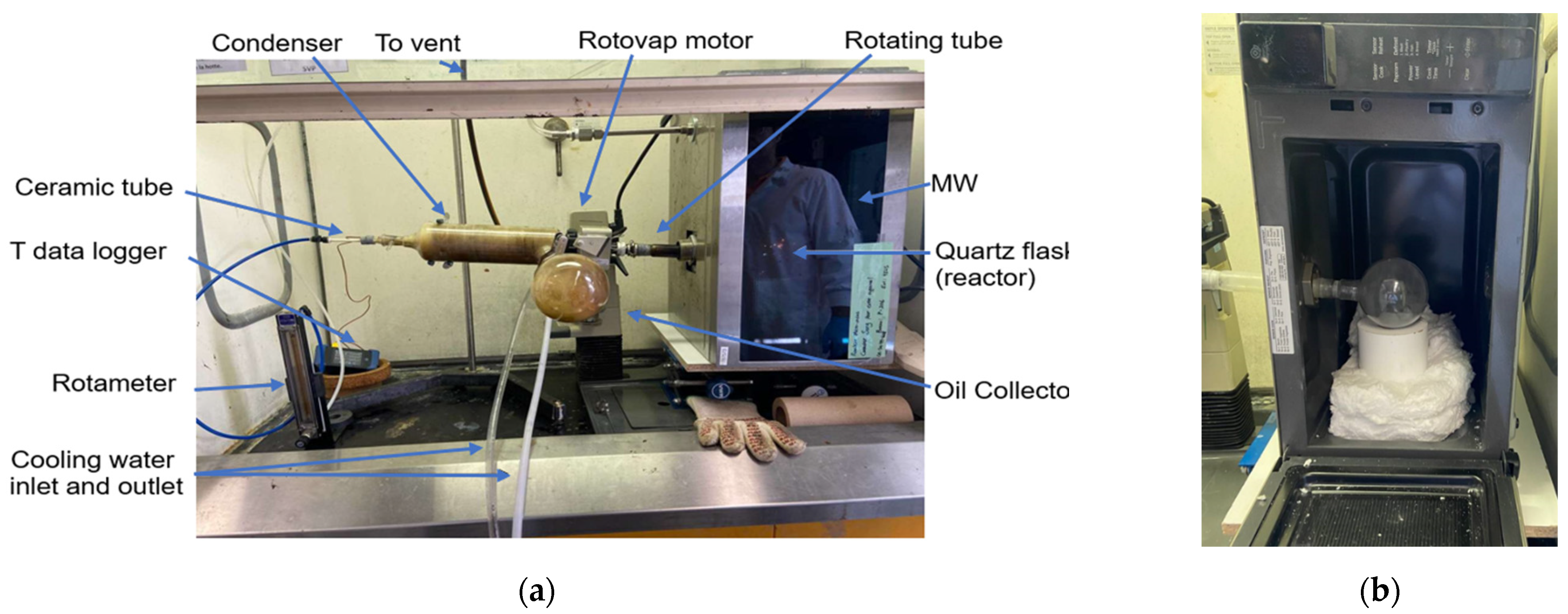
A Type-K thermocouple (ungrounded) was utilized to measure the temperature of the gas inside the quartz flask (the reactor), while a Type-J thermocouple was employed to monitor the temperature of the gas products at the outlet of the reactor. The flask was elevated using insulating glass wool and a Teflon bloc. These materials were selected for their dielectric properties. In fact, they exhibit excellent thermal insulating properties and they are nearly inert (transparent) to electromagnetic waves. A Buchi rotary evaporator RE111 (rotovap) from Buchi, DE, USA was used to rotate the flask and agitate the specimens to ensure a uniform distribution of microwaves in the reaction zone. The data logger monitored and registered the temperatures during the process. To purge the system, the ceramic tube injected nitrogen to remove oxygen from the flask, providing temperature homogeneity and removing the gaseous by-product of the pyrolysis reaction. The flow of nitrogen was controlled using a rotameter. The heavier gaseous by-products were liquified using the in-built diagonal Buchi rotovap condenser and collected in an oil collector flask. The light gases were vented through the fume hood. A bath circulator provided a constant flow of cold water to condense the by-products.
Figure 1 shows the experimental setup used in this study.
2.1. Reclamation Procedure
The reclamation procedure began with sample preparation. The expired prepreg roll was unrolled and both the released paper and separation foil were cut and removed from the area to be sampled. Furthermore, the prepreg sheet was cut into small pieces, i.e., approximately 15 mm × 15 mm, and the quartz flask was weighed to the nearest 0.001 g. Then, approximately 15 g of cut specimen was loaded into the flask. Subsequently, the flask was securely placed in the microwave cavity via a connection to the rotameter tube through a chucking hole. The setup installation was completed by connecting two thermocouples, the carrier gas ceramic tube, the condenser, the data logger, the rotameter, and all of the corresponding adaptors. Once system installation was completed, the circulating bath was applied to provide cooling water and to condition the system. In addition, the rotary motor speed was adjusted to the desired value. Before applying the microwave and starting the pyrolysis reaction, the system was purged using a controlled flow of nitrogen for a minimum of 10 min.
2.2. Design of Experiments via the Three-Level Box–Behnken RSM Tool
The Box–Behnken method is a design of experiments (DOEs) technique used to analyze and optimize complex systems with multiple variables. Its goal is to minimize the number of required trials while pinpointing the optimal input variable values for a given process [
30]. Experimental runs were conducted based on a fractional factorial design generated using the Box–Behnken approach, with each variable set at three different levels, representing low, medium, and high values. This methodology allowed for the evaluation of the linear and quadratic effects of the factors on the target response [
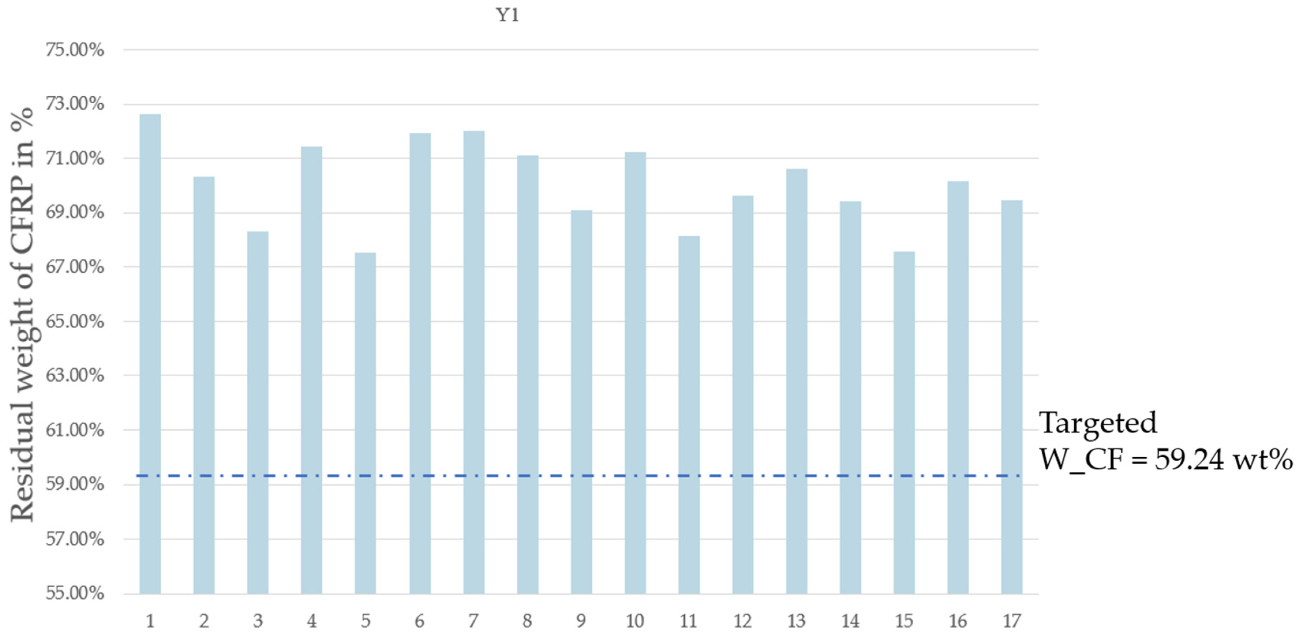
30]. In this study, the low, medium, and high values of the four influencing parameters (pyrolysis time, flow rate, power level, and On/Off rotation frequency) were determined during several preliminary experiments prior to microwave pyrolysis. A total of 17 experiments were conducted following a three-level Box–Behnken experimental design approach, with a designated range of variables as highlighted and classified in
Table 1,
Table 2 and
Table 3. When the On/Off rotation frequency value X4 is not 0, the pause time between the rotation cycles is 30 s.
2.3. Post-Pyrolysis Treatments
After pyrolysis, a carbon black residue remains on the surface of the fibers. In addition, some resin remains unreacted if the pyrolysis reaction was not completed. Therefore, various methods were separately tested to remove this residual resin and carbon black with the aim of evaluating the advantages and disadvantages of each technique.
Quartz sand, which is also known as silica sand, is a naturally occurring mineral primarily composed of silicon dioxide (SiO
2). It is a wear particle with dielectric properties that is suitable for the microwave applicator as it is mostly transparent to microwaves. The effect of sand particles is well-established in the literature. Moreover, they are commonly used in emerging technologies, especially for processes such as abrasion and machining [
31,
32,
33,
34,
35,
36,
37]. In this study, Ottawa sand (CAS 14808-60-7) was used to simulate mechanical abrasion on the samples during microwave pyrolysis. The objective of this evaluation was to assess whether the use of quartz sand during CFRP pyrolysis would prevent the need for a chemical or thermal post-pyrolysis process. Two experiments were conducted using quartz sand during pyrolysis in the microwave applicator. The microwave pyrolysis protocol described in
Section 2.1 was followed, with the only difference being that the quartz sand was weighed and introduced into the reactor along with the prepreg sample before pyrolysis. Accordingly, 50 g of quartz sand was placed in the reactor with 15 g of sample. In addition, the pyrolysis reaction was performed under the following conditions: 100% power, 914 W, 8 min, and 2.9 L/min of nitrogen flowrate. The Input power of the microwave applicator is 1100 W. The output power can be modulated using a control button labeled “DIAL POSITION”, which goes from 0 to 100%. Water calibration measurements were taken and made it possible to determine that the 100% position corresponds to 914 Watts on average. It should be noted that this is an experimental measurement, taken under laboratory conditions (21 °C, 50% RH) and that the temperature probe used can also introduce the phenomenon of reflectance, and therefore losses of energy by reflectance given that it is a metallic probe, which would have the effect of giving a result less than the true power received by the sample during the experiment.
- b.
Chemical dissolution using sulfuric acid and hydrogen peroxide mixture
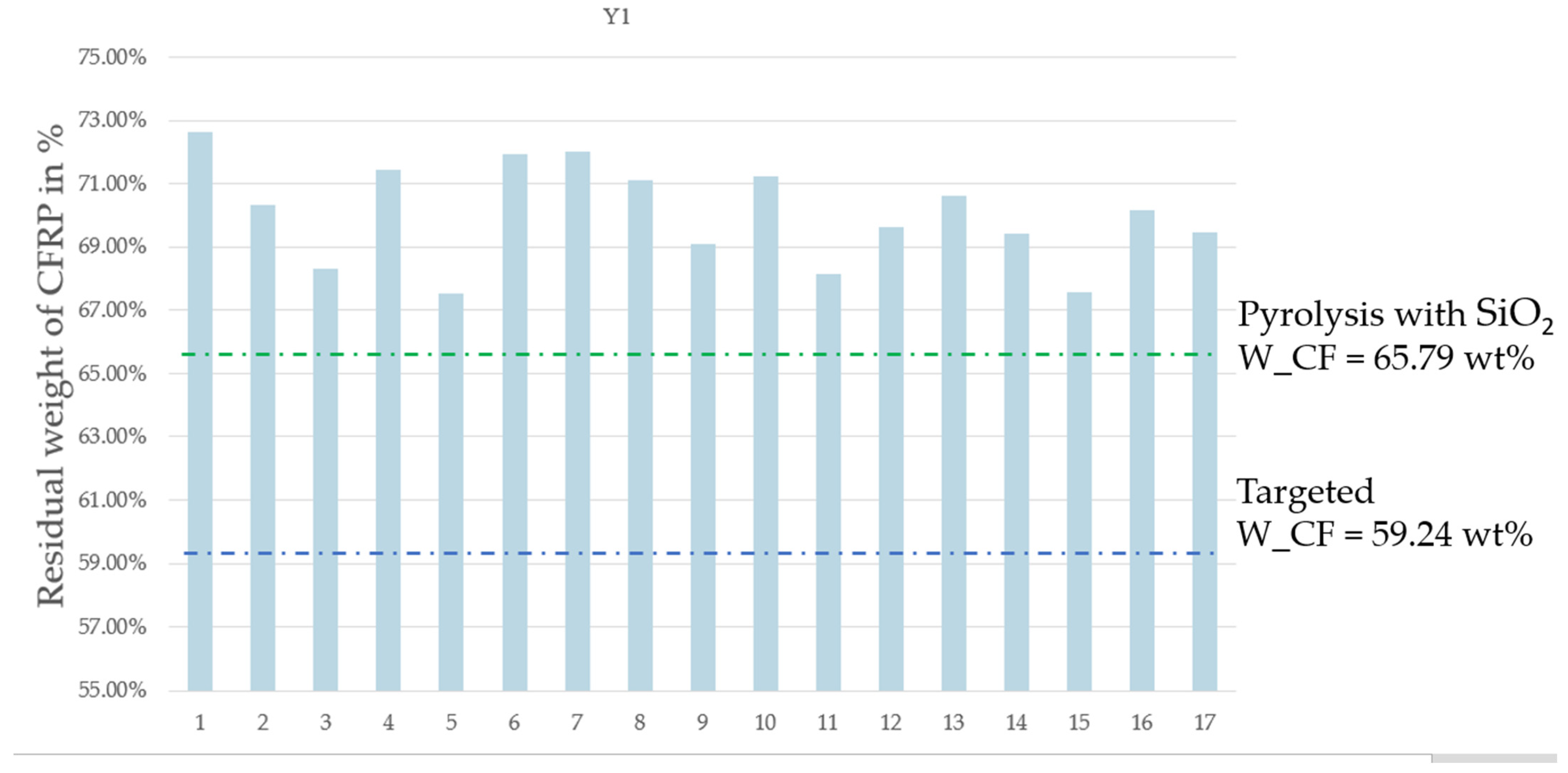
The chemical digestion procedure described in ASTM D3171 procedure B was employed to remove the residual carbon black and non-reacted resin. In this procedure, sulfuric acid with a boiling point above 330 °C is used to digest the resin system over a short period of time. In this study, the effective mass fraction of fiber after pyrolysis was assessed as per ASTM D3171 B. This is one of the most accurate techniques to determine the mass fraction of carbon fiber in CFRP, as the hot sulfuric acid only digests the carbon black and the epoxy resin system and does not attack the carbon fiber. For each post-pyrolysis trial, the effective weight fraction of remaining resin (Wm) was determined and compared with the initial mass fraction of the resin in the prepreg.
- c.
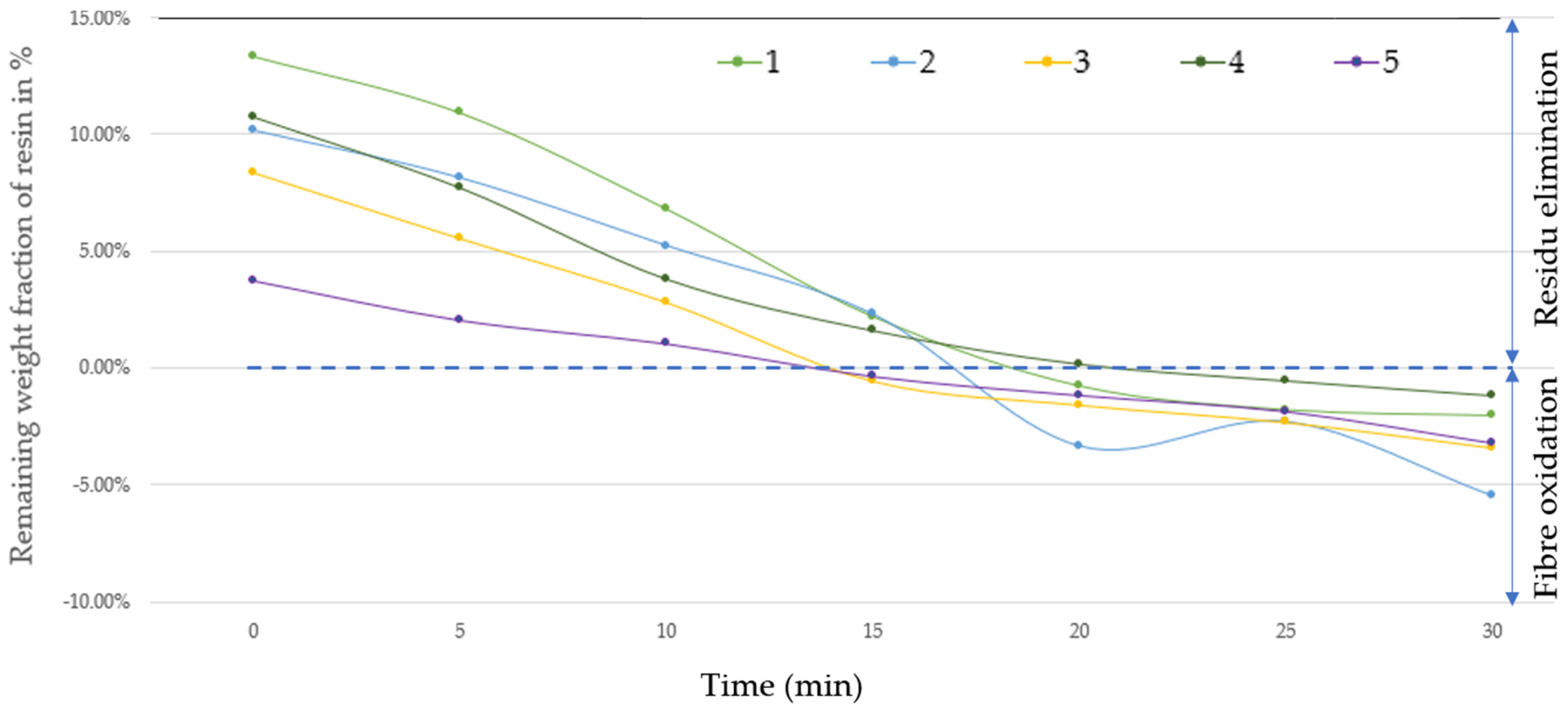
Thermal oxidation
Two types of thermal oxidation, i.e., via the microwave applicator and using a conventional furnace, were performed under air after MAP. Conventional thermal oxidation was performed at 540 °C using a conventional furnace over 6 durations: 5, 10, 15, 20, 25, and 30 min. Microwave thermal oxidation was performed using the microwave applicator shown in
Figure 1 at full power (914 W) at durations of 5, 10, and 15 min.
2.4. Characterization of Recycled Carbon Fiber (TGA, SEM, and XPS)
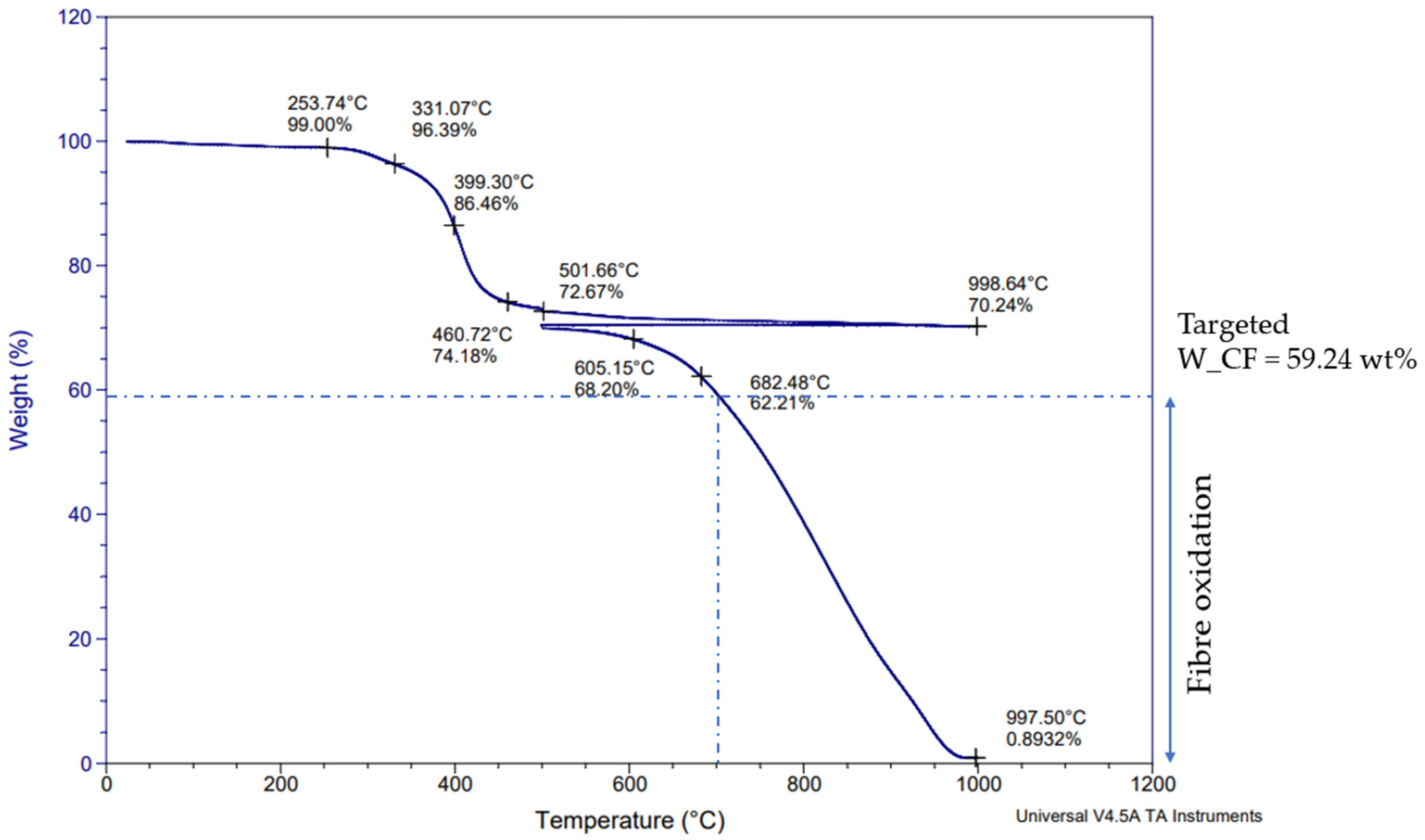
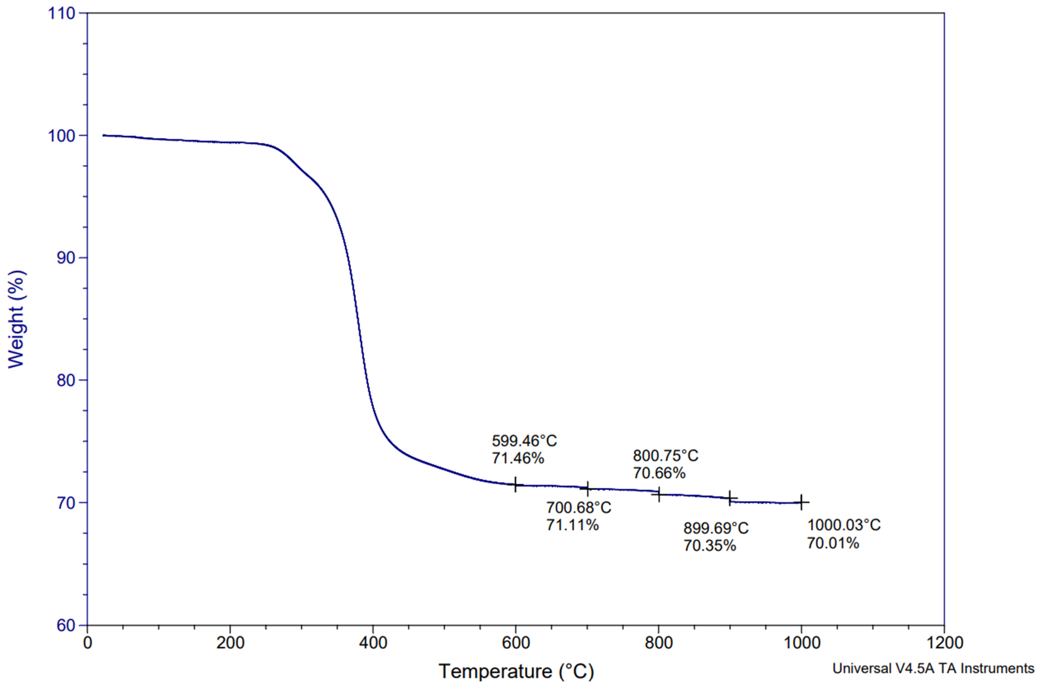
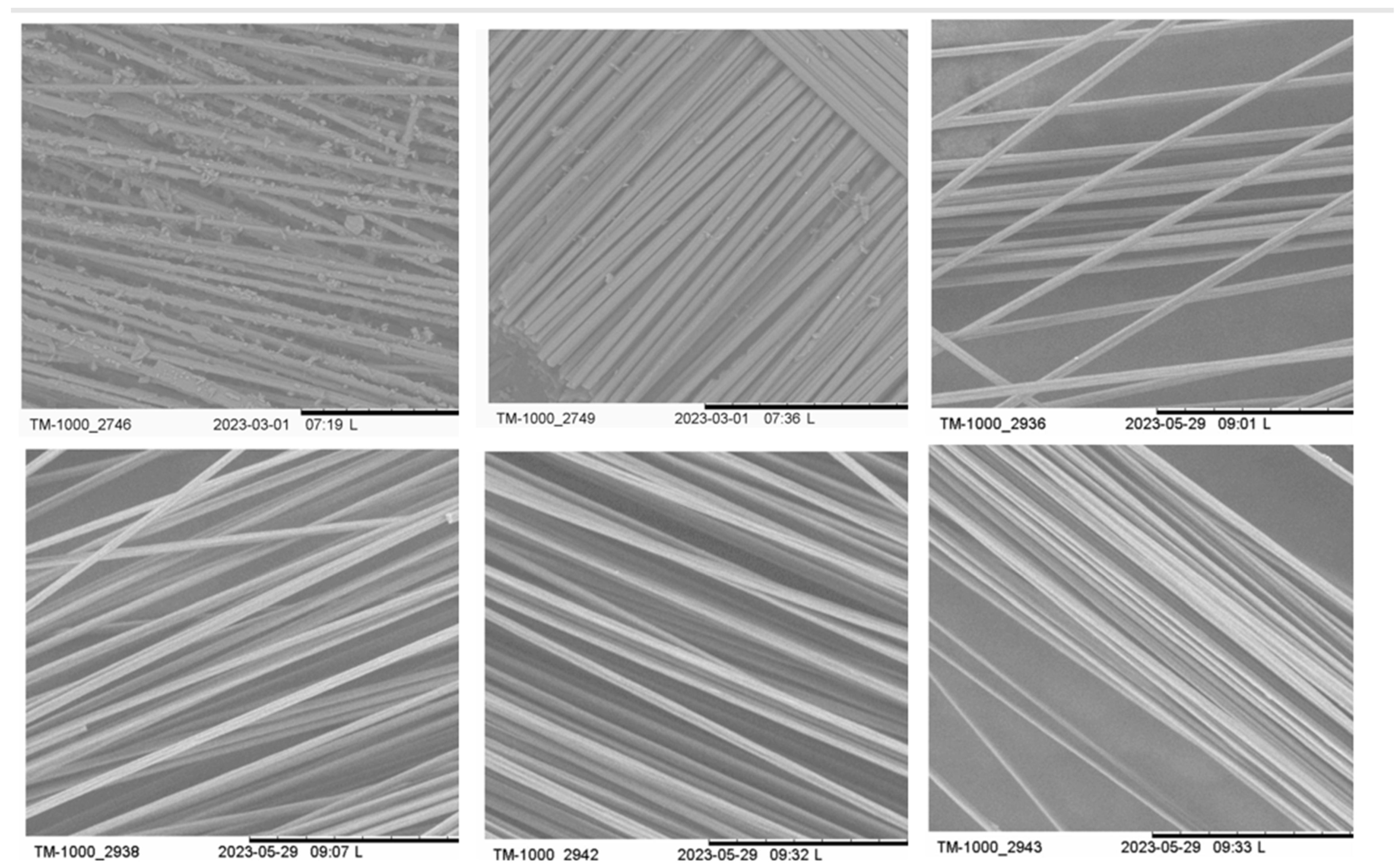
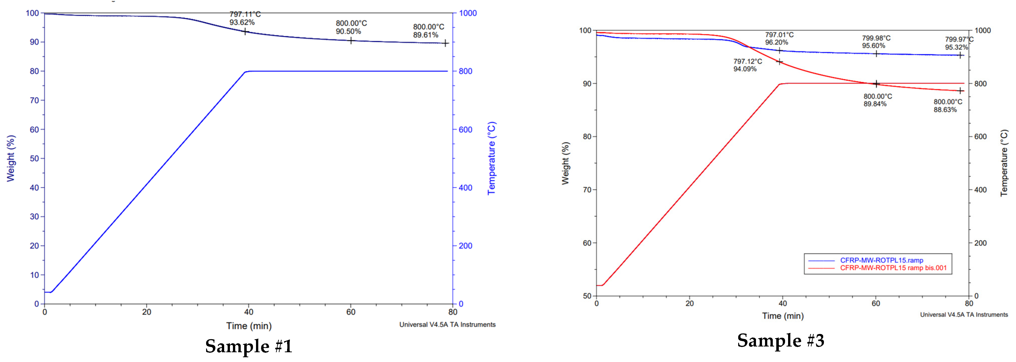
The weight fraction of the epoxy matrix and carbon fiber in the samples was estimated, both pre- and post-pyrolysis, using thermogravimetric analysis (TGA). TGA tests were conducted under a nitrogen atmosphere with a heating rate of 10 °C/min. This began at room temperature and went up to 1000 °C, followed by an isothermal hold for 1 h. The 1 h isothermal hold under nitrogen was followed by a return to 500 °C, after which heating under air was applied until 1000 °C for 30 min in order to simulate thermal degradation under air. After pyrolysis, the surface morphology of the recovered carbon fibers was examined using scanning electron microscopy (SEM). SEM imaging was performed using a HITACHI TM-1000 scanning electron microscope from HITACHI high-Tech, Toronto, ON, Canada. Furthermore, X-ray photoelectron spectroscopy (XPS) was performed on the recovered carbon fibers. The apparatus used for the XPS analysis was a VG ESCALAB 250Xi X-ray Photoelectron Spectrometer from Thermofisher, Waltham, MA, USA. A maximum depth of 10 nm was analyzed using XPS.
4. Conclusions
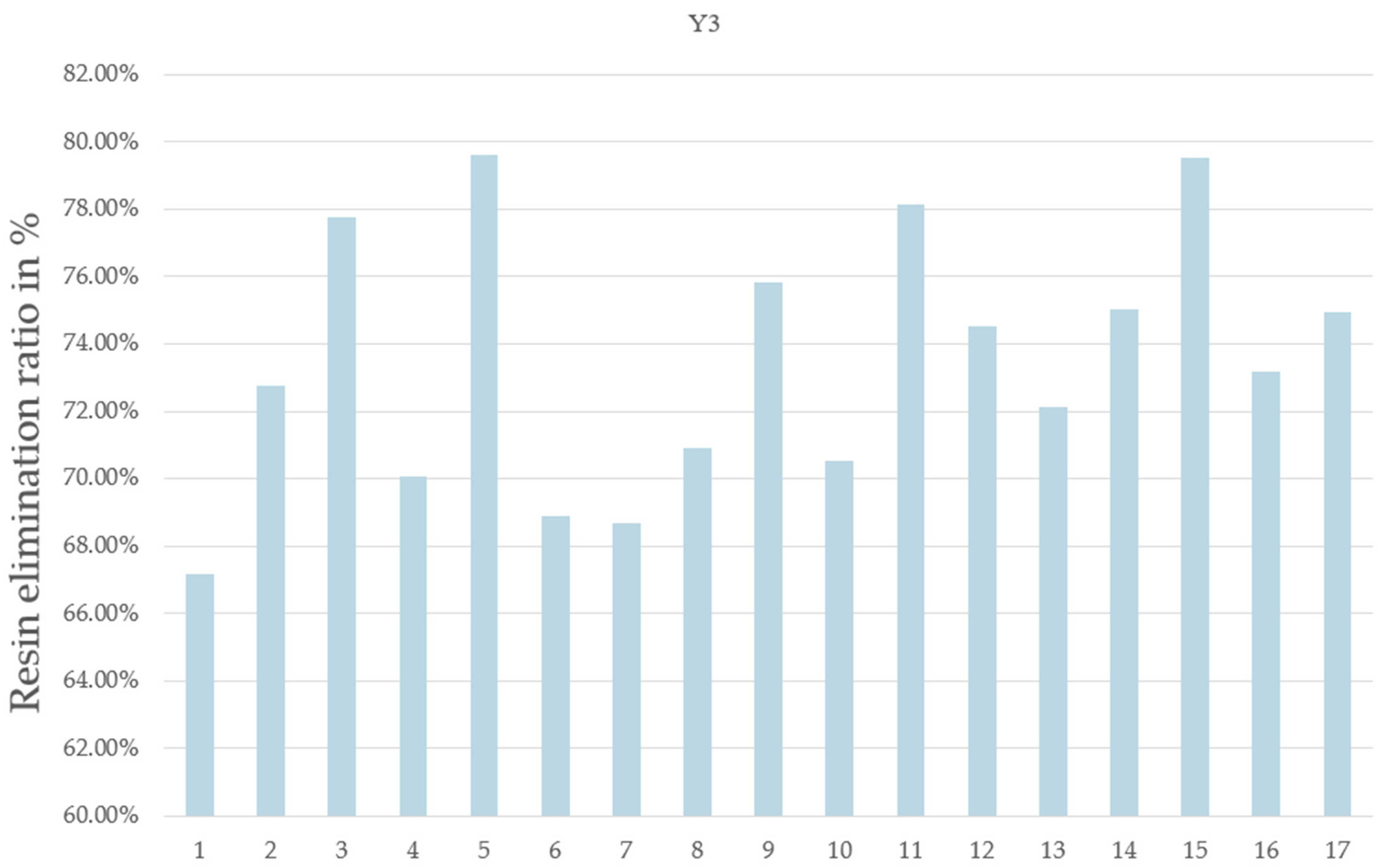
This article presents an eco-friendly method for reclaiming carbon fiber-reinforced polymers (CFRPs). The study aimed to investigate the key parameters affecting the microwave-assisted decomposition of CFRPs. Through numerous experiments using microwave-assisted pyrolysis (MAP), factors such as the inert gas flow, power level, On/Off rotation frequency, and reaction duration were explored. The results show that the developed models accurately predicted the main influencing parameters in the microwave-assisted decomposition of CFRPs. The optimal operating conditions were found to be a nitrogen flow of 2.9 L/min and a power level of 914 Watts (100% power). Additionally, it was observed that the On/Off rotation frequency of the reactor vessel and increasing the reaction time beyond 6 min did not significantly affect the resin elimination percentage in comparison to the two other parameters, i.e., power and flow rate. The optimum conditions led to a maximum resin elimination percentage of 79.6%. After successful MAP, various post-pyrolysis treatments were used to remove char and non-reacted resin from the surface of the recovered carbon fibers, namely, thermal oxidative treatment using a microwave (MW) applicator, thermal oxidative treatment in a conventional furnace, mechanical abrasion with quartz sand, and chemical digestion. Among these techniques, thermal oxidation and chemical digestion were found to be the most efficient, leading to 100% of the carbon black content on the surface of recovered carbon fibers being eliminated. The efficiency of the post-treatments was established using SEM evaluations and the XPS analysis of the recovered carbon fibers. In conclusion, using a microwave applicator, the complete carbon fiber recovery process can be achieved in just 16 min, i.e., approximately 6 min for pyrolysis and 10 min for thermal oxidation. Given the environmental crisis and the goal of achieving carbon neutrality by 2050, this technology offers a less energy-intensive and environmentally friendly alternative to conventional pyrolysis technologies, as the heating mechanism involved induced less energy loss [
27]. The products generated avoid the extraction of petroleum materials, thereby reducing greenhouse gas emissions. The production of recycled carbon fiber is significantly less expensive than the production of virgin fibers, costing USD 18 to 26 per kilogram compared to USD 35 to 65 per kilogram. Additionally, the process of producing recycled carbon fiber emits substantially less CO
2, producing 4.65 tonnes of CO
2 per tonne of recycled fiber versus 29.45 tonnes of CO
2 per tonne of virgin fiber [
7,
8]. Limitations of such a study include the assumptions and fixed parameters used for the optimization study, as presented in detail in
Section 2.2. Future work will consist in the refinement of the identified parameters that have a positive influence on the CFRP decomposition, i.e., flow rate and the level of power.


 ,
, 