
Redox Stability Optimization in Anode-Supported Solid Oxide Fuel Cells

Abstract
:1. Introduction
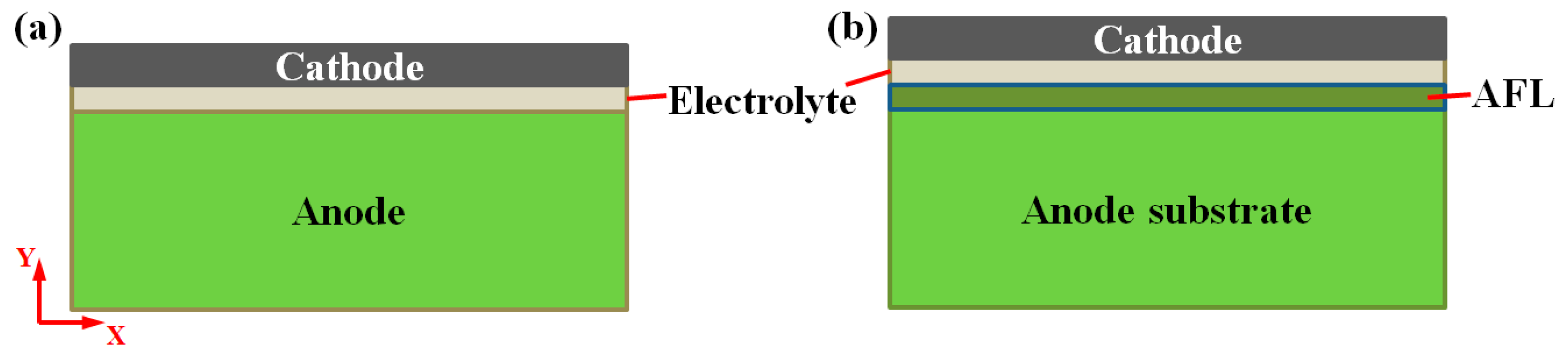
2. Analytical Model
3. Results and Discussion
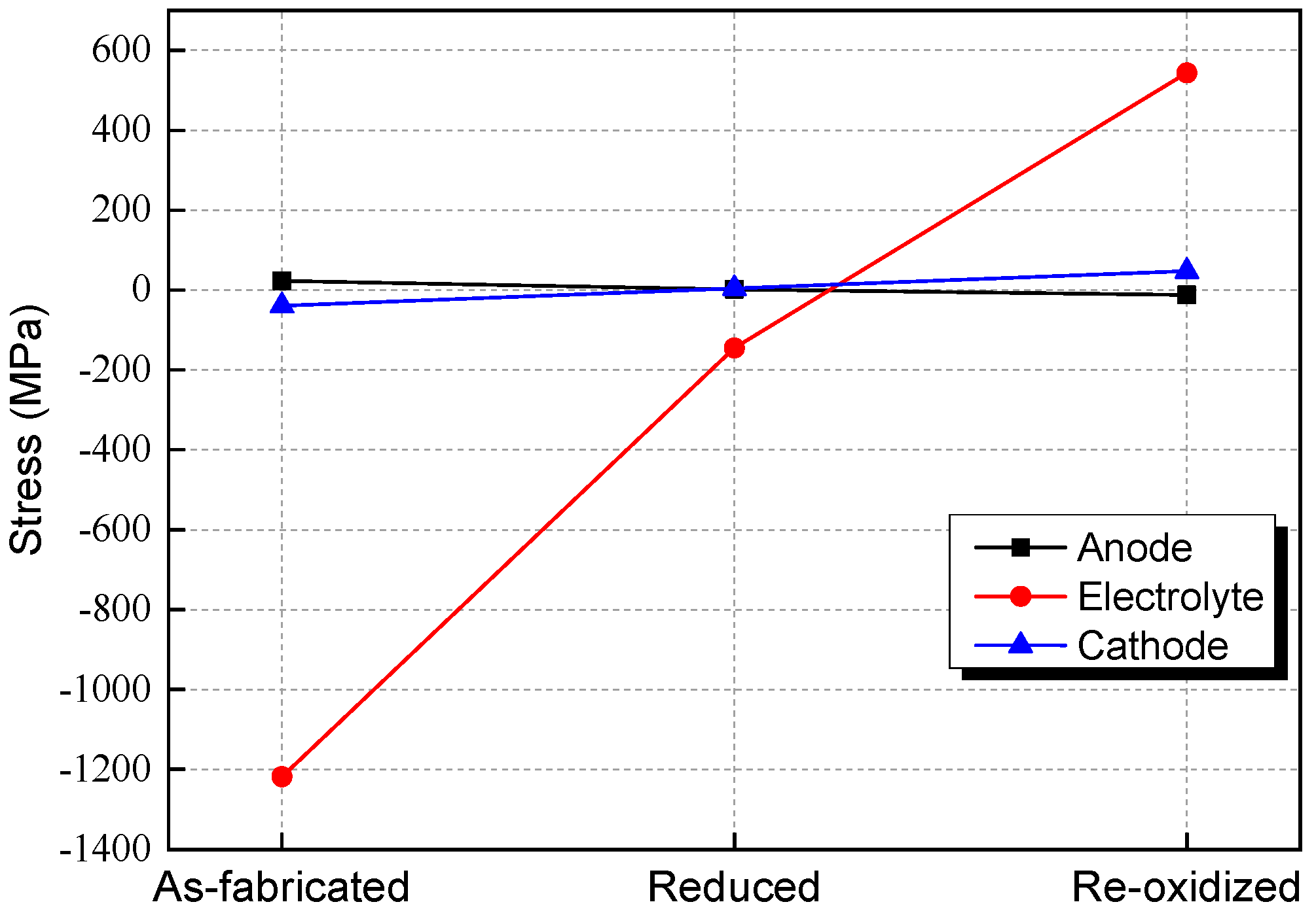
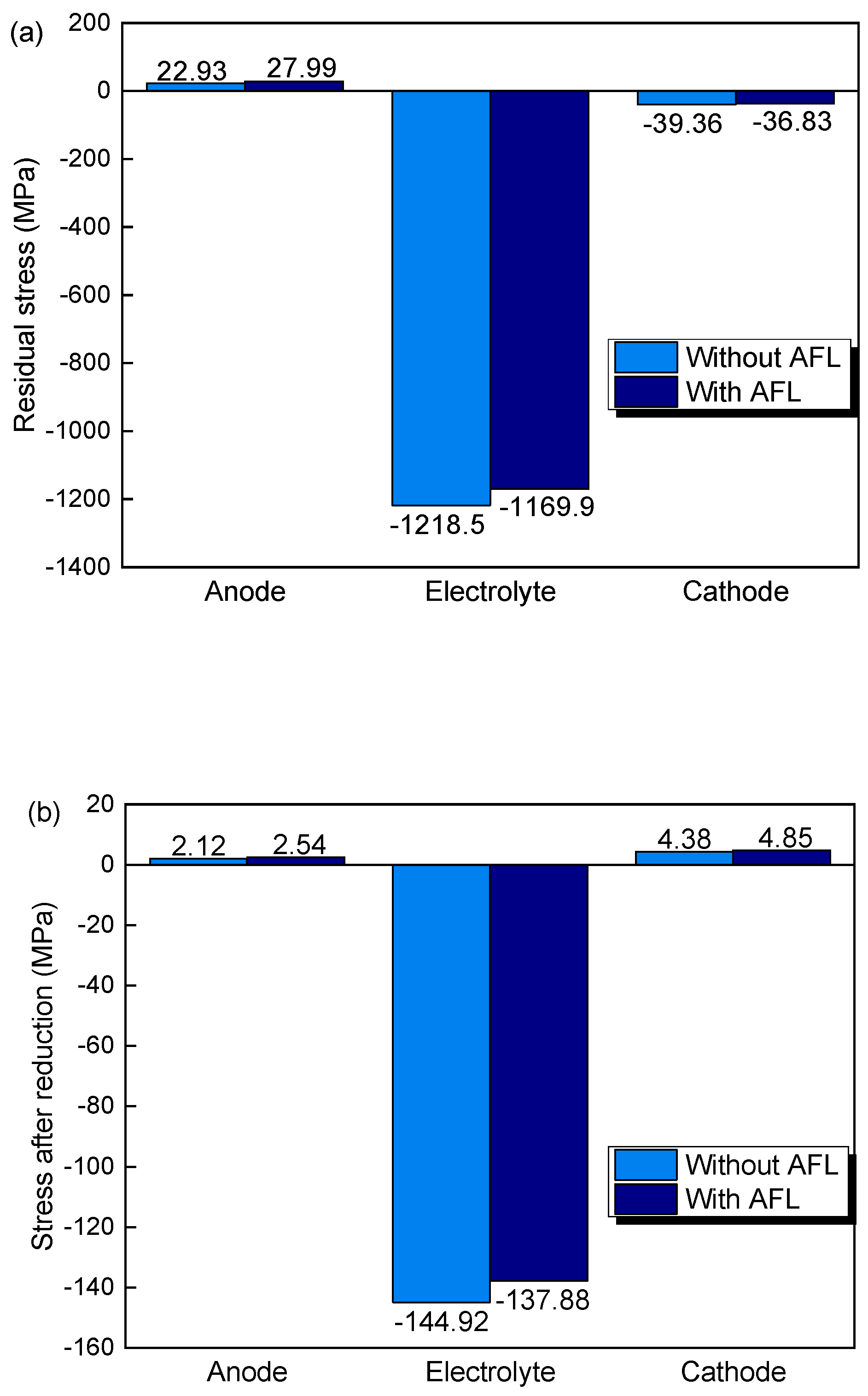
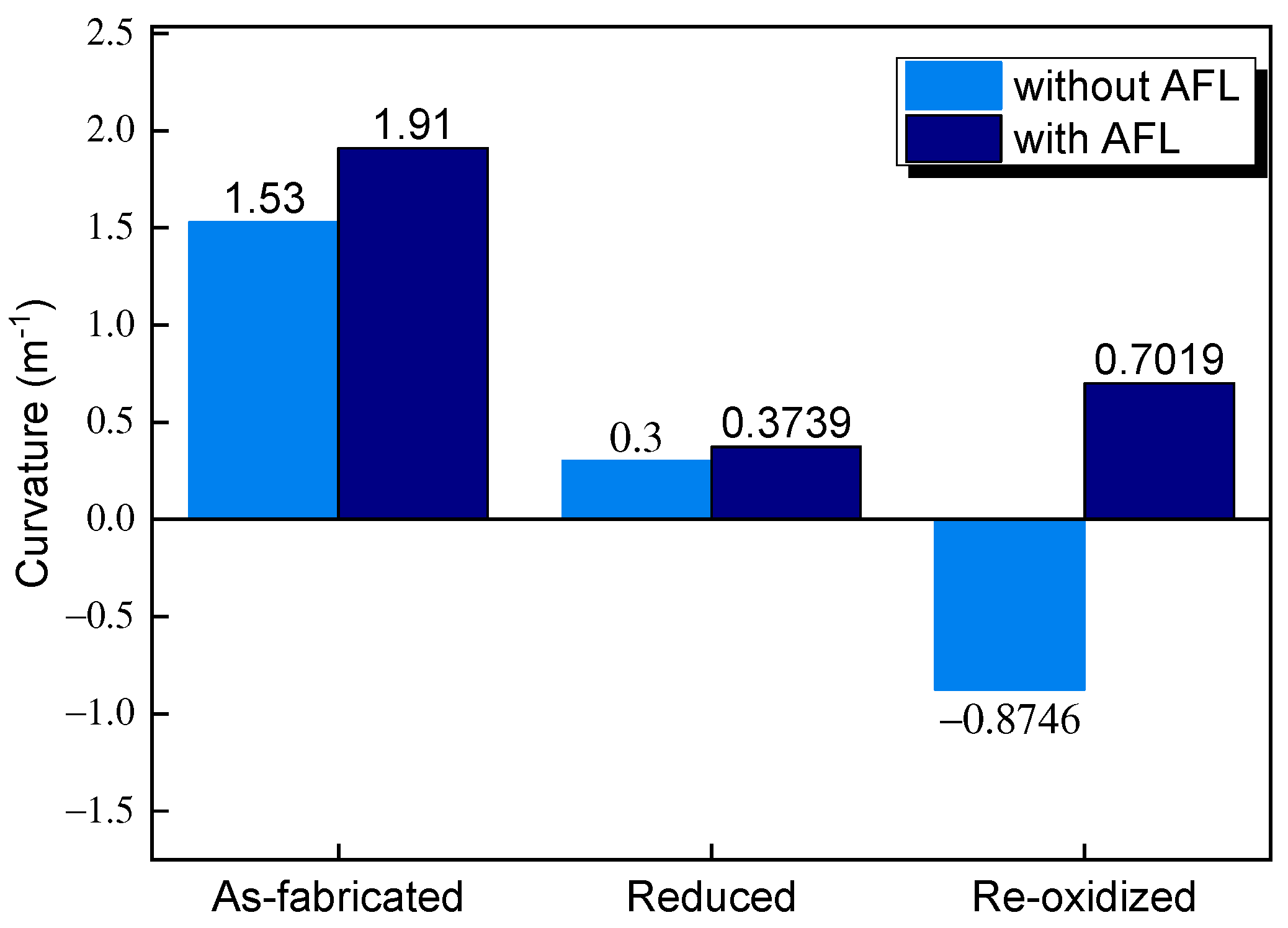
3.1. Stress Evolution during Redox
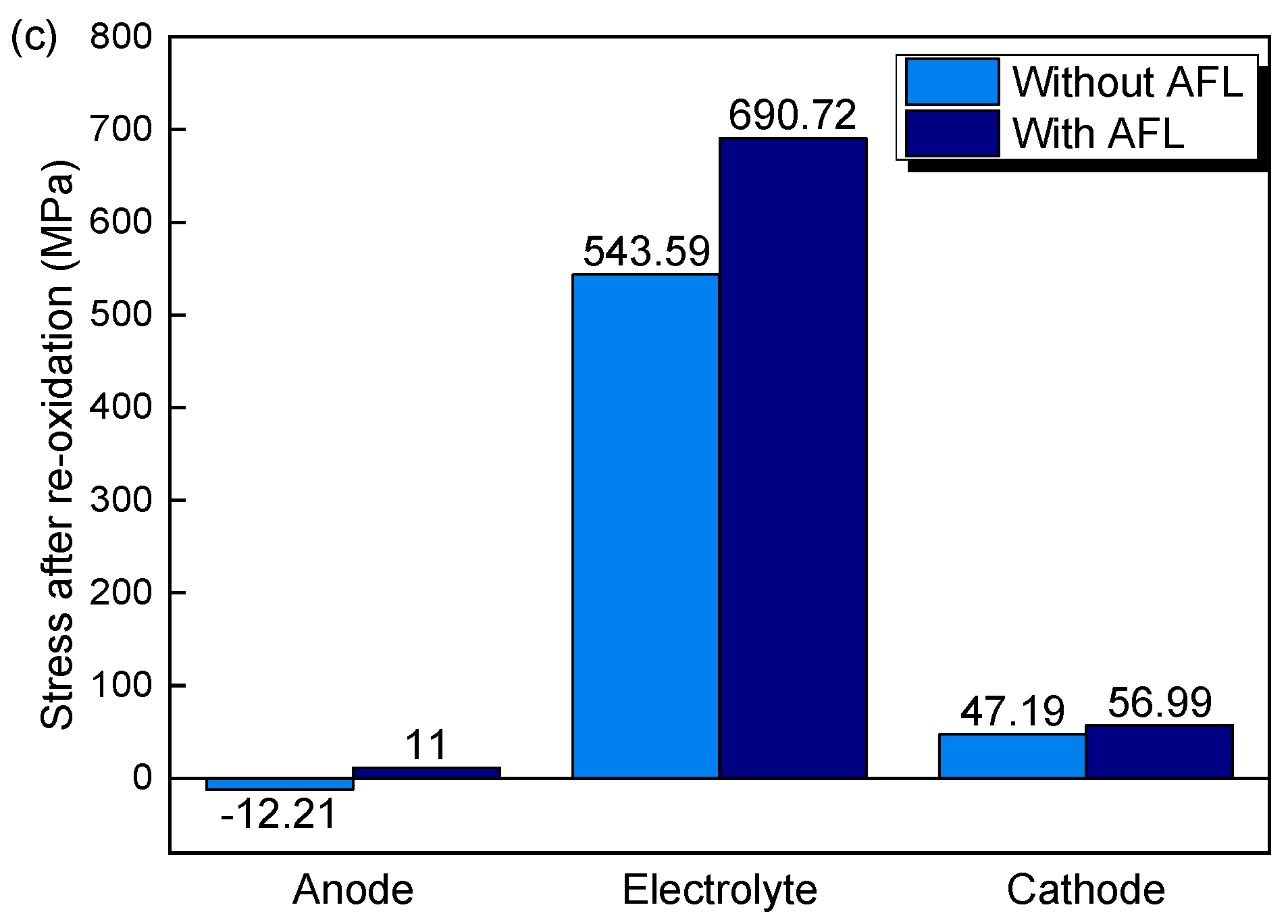
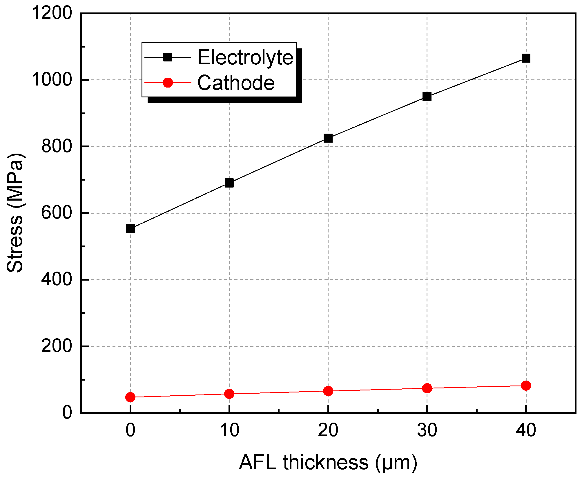
3.2. The Effects of AFL and Anode Substrate Thickness on Stress after Re-Oxidation
4. Discussion
4.1. Model Validation
4.2. Results Discussion
5. Conclusions
- AFL re-oxidation has a great effect on the stress of the structure. By introducing an AFL on the anode substrate, the tensile stresses of the electrolyte and cathode of the SOFC with an AFL are increased by 27.07% and 20.77%, respectively, compared with the stresses of the SOFC without an AFL after the full re-oxidation of the anode.
- After re-oxidation, the stresses of the electrolyte layer and cathode layers are increased with increasing AFL thickness. The stresses in the electrolyte and cathode with a 40 μm AFL are almost one time larger than those without an AFL. An SOFC with an AFL thickness of about 10 μm is superior for better electrical performance and redox stability.
- The thickness of the anode substrate plays a more important role in the SOFC without an AFL than in the SOFC with an AFL. By increasing the thickness of the anode substrate, the stresses in the electrolyte and cathode decrease.
Author Contributions
Funding
Data Availability Statement
Conflicts of Interest
Nomenclature
| Abbreviation | |
| SOFCs | solid oxide fuel cells |
| AFL | anode functional layer |
| CTE | thermal expansion coefficient |
| Symbols | |
| Ei | Young’s modulus, MPa |
| υi | Poisson’s ratio, - |
| αi | thermal expansion coefficient, °C−1 |
| T | temperature, °C |
| σi | stress, MPa |
| εi | strain, - |
| k | curvature, - |
| ti | thickness, m |
| Subscripts and superscripts | |
| s | anode substrate |
| f | AFL |
| e | electrolyte |
| c | cathode |
| ox | oxidation |
| th | thermal expansion |
References
- Xu, Q.D.; Guo, Z.J.; Xia, L.C.; He, Q.; Li, Z.; Bello, I.T.; Zheng, K.; Ni, M. A comprehensive review of solid oxide fuel cells operating on various promising alternative fuels. Energy Convers. Manag. 2022, 253, 115175. [Google Scholar] [CrossRef]
- Papurello, D.; Canuto, D.; Santarelli, M. CFD model for tubular SOFC stack fed directly by biomass. Int. J. Hydrogen Energy 2022, 47, 6860–6872. [Google Scholar] [CrossRef]
- Lin, C.; Kerscher, F.; Herrmann, S.; Steinrücken, B.; Spliethoff, H. Analysis on temperature uniformity in methane-rich internal reforming solid oxide fuel cells (SOFCs). Int. J. Hydrogen Energy 2024, 57, 769–788. [Google Scholar] [CrossRef]
- Liu, S.; Du, P.; Jia, H.; Zhang, Q.; Hao, L. Study on the impact of methanol steam reforming reactor channel structure on hydrogen production performance. Int. J. Hydrogen Energy 2024, 228, 120612. [Google Scholar] [CrossRef]
- Rangel-Hernandez, V.; Haart, U.D.; Fang, Q.; Schäfer, D.; Thaler, F.; Peters, R.; Blum, L. An Investigation of the Redox Stability of an Anode-Supported SOFC Stack Using Acoustic Emission Monitoring. ECS Trans. 2021, 103, 1395–1402. [Google Scholar] [CrossRef]
- Ma, L.; Wang, Y.; Li, W.; Guan, B.; Qi, H.; Tian, H.; Zhou, L.; De Santiago, H.A.; Liu, X. Redox-stable symmetrical solid oxide fuel cells with exceptionally high performance enabled by electrode/electrolyte diffuse interface. J. Power Sources 2021, 488, 229458. [Google Scholar] [CrossRef]
- Nguyen, B.N.; Karri, N.K.; Mason, C.T.; Fitzpatrick, J.F.; Koeppel, B.J. A mechanistic damage model for solid oxide fuel cell ceramic materials—Part I: Constitutive modeling. Int. J. Hydrogen Energy 2022, 47, 7388–7402. [Google Scholar] [CrossRef]
- Matsumoto, K.; Tachikawa, Y.; Matsuda, J.; Taniguchi, S.; Sasaki, K. Redox Durability of Ni-Co Alloy Cermet Anodes for SOFCs. ECS Trans. 2021, 103, 1549–1556. [Google Scholar] [CrossRef]
- Timurkutluk, B.; Mat, M.D. Effects of anode fabrication parameters on the performance and redox behavior of solid oxide fuel cells. J. Power Sources 2014, 258, 108–116. [Google Scholar] [CrossRef]
- Wang, Y.; Jiang, W.; Luo, Y.; Zhang, Y.; Tu, S.-T. Evolution of thermal stress and failure probability during reduction and re-oxidation of solid oxide fuel cell. J. Power Sources 2017, 371, 65–76. [Google Scholar] [CrossRef]
- Laurencin, J.; Delette, G.; Morel, B.; Lefebvre-Joud, F.; Dupeux, M. Solid oxide fuel cells damage mechanisms due to Ni-YSZ re-oxidation: Case of the anode supported cell. J. Power Sources 2009, 192, 344–352. [Google Scholar] [CrossRef]
- Mukhopadhyay, M.; Sharma, A.D.; Mukhopadhyay, J. Anode supported SOFC fabricated with functional anode: Role of variation of fuel and oxidants. J. Phys. Conf. Ser. 2020, 1579, 012001. [Google Scholar] [CrossRef]
- Kupecki, J.; Kluczowski, R.; Papurello, D.; Lanzini, A.; Kawalec, M.; Krauz, M.; Santarelli, M. Characterization of a circular 80 mm anode supported solid oxide fuel cell (AS-SOFC) with anode support produced using high-pressure injection molding (HPIM). Int. J. Hydrogen Energy 2018, 44, S0360319918306463. [Google Scholar] [CrossRef]
- Xiao, J.; Zeng, X.; Li, M.; Dong, P.; Wu, H.; Xu, M.; Lin, Y.; Liu, J.; Xie, Y.; Zhang, Y. Effect of pre-calcined ceramic powders at different temperatures on Ni-YSZ anode-supported SOFC cell/stack by low pressure injection molding. Ceram. Int. 2019, 45, 20066–20072. [Google Scholar] [CrossRef]
- Zhang, Q.; Xie, K.; Luo, Y.; Zhang, Y.-C.; Jiang, W.-C. Mismatch effect of material creep strength on creep damage and failure probability of planar solid oxide fuel cell. Int. J. Hydrogen Energy 2022, 47, 2673–2684. [Google Scholar] [CrossRef]
- Pihlatie, M.; Ramos, T.; Kaiser, A. Testing and improving the redox stability of Ni-based solid oxide fuel cells. J. Power Sources 2009, 193, 322–330. [Google Scholar] [CrossRef]
- Waldbillig, D.; Wood, A.; Ivey, D.G. Thermal analysis of the cyclic reduction and oxidation behaviour of SOFC anodes. Solid State Ion. 2005, 176, 847–859. [Google Scholar] [CrossRef]
- Kharchenko, Y.; Blikharskyy, Z.; Vira, V.; Vasyliv, B.D.; Podhurska, V.Y.; Kalynovskyy, A.; Korendiy, V. Nanostructural Changes in a Ni/NiO Cermet During High-Temperature Reduction and Reoxidation. In Nanomaterials and Nanocomposites, Nanostructure Surfaces, and Their Applications; Springer: Berlin/Heidelberg, Germany, 2021. [Google Scholar] [CrossRef]
- Wood, A.; Pastula, M.; Waldbillig, D.; Ivey, D.G. Initial Testing of Solutions to Redox Problems with Anode-Supported SOFC. J. Electrochem. Soc. 2006, 153, A1929–A1934. [Google Scholar] [CrossRef]
- Kim, J.W.; Bae, K.; Kim, H.J.; Son, J.-W.; Kim, N.; Stenfelt, S.; Prinz, F.B.; Shim, J.H. Three-dimensional thermal stress analysis of the re-oxidized Ni-YSZ anode functional layer in solid oxide fuel cells. J. Alloys Compd. 2018, 752, 148–154. [Google Scholar] [CrossRef]
- Malzbender, J. Reduction and Re-Oxidation of Anodes for Solid Oxide Fuel Cells (SOFC). Ceram. Eng. Sci. Proced. 2004, 25, 387. [Google Scholar]
- Zhang, X.; Yu, S.; Wang, M.; Dong, S.; Parbey, J.; Li, T.; Andersson, M. Thermal stress analysis at the interface of cathode and electrolyte in solid oxide fuel cells. Int. Commun. Heat Mass Transf. 2020, 118, 104831. [Google Scholar] [CrossRef]
- Nakajo, A.; Kuebler, J.; Faes, A.; Vogt, U.F.; Schindler, H.J.; Chiang, L.-K.; Modena, S.; Van Herle, J.; Hocker, T. Compilation of mechanical properties for the structural analysis of solid oxide fuel cell stacks. Constitutive materials of anode-supported cells. Ceram. Int. 2012, 38, 3907–3927. [Google Scholar] [CrossRef]
- Nakajo, A.; Herle, J.V.; Favrat, D. Sensitivity of Stresses and Failure Mechanisms in SOFCs to the Mechanical Properties and Geometry of the Constitutive Layers. Fuel Cells 2011, 11, 537–552. [Google Scholar] [CrossRef]
- Biswas, S.; Nithyanantham, T.; Saraswathi, N.T.; Bandopadhyay, S. Evaluation of elastic properties of reduced NiO-8YSZ anode-supported bi-layer SOFC structures at elevated temperatures in ambient air and reducing environments. J. Mater. Sci. 2009, 44, 778–785. [Google Scholar] [CrossRef]
- Wang, Y.; Jiang, W.; Song, M.; Luo, Y.; Tu, S.-T. Effect of inhomogeneous oxidation on the mechanical degradation of anode supported solid oxide fuel cell. J. Power Sources 2020, 450, 227663. [Google Scholar] [CrossRef]
- Lu, Y.J.; Yi, Y.; Wang, F.H.; Lou, K.; Zhao, X. Effect of continuously graded functional layer on curvature and residual stress of solid oxide fuel cell in initial reduction process. Acta Phys. Sin. 2016, 65, 098102. [Google Scholar]
- Klemensø, T. Relationships between Structure and Performance of SOFC Anodes. Ph.D. Thesis, Technical University of Danemark, Risoe National Laboratory, Topsoe Fuel Cell, Risø, Denmark, 2005. [Google Scholar]
- Zhang, X.C.; Xu, B.S.; Wang, H.D.; Wu, Y. An analytical model for predicting thermal residual stresses in multilayer coating systems. Thin Solid Film. 2005, 488, 274–282. [Google Scholar] [CrossRef]
- Watanabe, S.; Sato, K.; Iguchi, F.; Yashiro, K.; Hashida, T.; Kawada, T. Mechanical Strength Evaluation of YSZ, GDC and LSCF under SOFC Operating Conditions. ECS Transcantions 2017, 78, 2181–2190. [Google Scholar] [CrossRef]
- Wei, J.; Osipova, T.; Malzbender, J.; Krüger, M. Mechanical characterization of SOFC/SOEC cells. Ceram. Int. 2018, 44, 11094–11100. [Google Scholar] [CrossRef]
- Shakrawar, S.; Pharoah, J.G.; Peppley, B.A.; Beale, S.B. A Review of Stress Analysis Issues for Solid Oxide Fuel Cells. In Proceedings of the ASME 2010 International Mechanical Engineering Congress and Exposition, Vancouver, BC, Canada, 12–18 November 2010; pp. 983–991. [Google Scholar]
- Wang, Z.; Zhang, N.; Qiao, J.; Sun, K.; Xu, P. Improved SOFC performance with continuously graded anode functional layer. Electrochem. Commun. 2009, 11, 1120–1123. [Google Scholar] [CrossRef]
- Zhang, T.; Zhu, Q.; Huang, W.L.; Xie, Z.; Xin, X. Stress field and failure probability analysis for the single cell of planar solid oxide fuel cells. J. Power Sources 2008, 182, 540–545. [Google Scholar] [CrossRef]
- Hagen, A.; Wulff, A.C.; Zielke, P.; Sun, X.; Talic, B.; Ritucci, I.; Frandsen, H.; Jensen, S.; Kiebach, W.; Hendriksen, P. SOFC stacks for mobile applications with excellent robustness towards thermal stresses. Int. J. Hydrogen Energy 2020, 45, 29201–29211. [Google Scholar] [CrossRef]
- Khanafer, K.; Al-Masri, A.; Vafai, K.; Preethichandra, P. Heat up impact on thermal stresses in SOFC for mobile APU applications: Thermo-structural analysis. Sustain. Energy Technol. Assess. 2022, 52, 102159. [Google Scholar] [CrossRef]
- Pihlatie, M.; Kaiser, A.; Mogensen, M. Mechanical Properties of NiO/Ni-YSZ Composites Depending on Temperature, Porosity and Redox Cycling. J. Eur. Ceram. Soc. 2009, 29, 1657–1664. [Google Scholar] [CrossRef]
- Faes, A.; Hessler-Wyser, A.; Zryd, A.; Van Herle, J. A Review of RedOx Cycling of Solid Oxide Fuel Cells Anode. Membranes 2012, 2, 585–664. [Google Scholar] [CrossRef]
- Abideen, Z.U.; Maqsood, A. Structural and ionic conduction study of Sm–Pr co-doped ceria electrolyte materials for LT-SOFC applications. Ceram. Int. 2024, 50, 21964–21977. [Google Scholar] [CrossRef]


| Component | Anode | Electrolyte | Cathode |
|---|---|---|---|
| Thickness (m × 10−6) | 600 | 10 | 40 |
| Material | NiO/Ni-YSZ | YSZ | LSCF |
| Temperature (°C) | Ni-YSZ | NiO-YSZ | AFL | YSZ | LSCF | |
|---|---|---|---|---|---|---|
| Young’s modulus (GPa) | 25 | 106 | 153 | 200 | 10 | |
| 800 | 64.769 | 101 | 129 110.8845 | 157 | 10 | |
| Thermal expansion coefficient (°C−1 × 10⁻⁶) | 25 | 11.7 | 9.65 | 7.6 | 8.8 | |
| 800 | 12.41 | 12.41 | 11.205 | 10 | 12.84 | |
| Poisson’s ratio | 25 | 0.301 | 0.3 | 0.31 | 0.3 | |
| 800 | 0.287 | 0.3 | 0.3 | 0.31 | 0.3 |
| Material | Temperature (°C) | NiO-YSZ | YSZ | LSCF |
|---|---|---|---|---|
| Fracture strength (MPa) | 25 | 187 | 232 | 52 |
| 800 | 124 | 154 | 75 |
Disclaimer/Publisher’s Note: The statements, opinions and data contained in all publications are solely those of the individual author(s) and contributor(s) and not of MDPI and/or the editor(s). MDPI and/or the editor(s) disclaim responsibility for any injury to people or property resulting from any ideas, methods, instructions or products referred to in the content. |
© 2024 by the authors. Licensee MDPI, Basel, Switzerland. This article is an open access article distributed under the terms and conditions of the Creative Commons Attribution (CC BY) license (https://creativecommons.org/licenses/by/4.0/).
Share and Cite
Wang, Y.; Song, M. Redox Stability Optimization in Anode-Supported Solid Oxide Fuel Cells. Materials 2024, 17, 3257. https://doi.org/10.3390/ma17133257
Wang Y, Song M. Redox Stability Optimization in Anode-Supported Solid Oxide Fuel Cells. Materials. 2024; 17(13):3257. https://doi.org/10.3390/ma17133257
Chicago/Turabian StyleWang, Yu, and Ming Song. 2024. "Redox Stability Optimization in Anode-Supported Solid Oxide Fuel Cells" Materials 17, no. 13: 3257. https://doi.org/10.3390/ma17133257