

Development and Implementation of Die Forging Technology Eliminating Flange Welding Operations in Conveyor Driver Forging
 , , ,
, , ,
Abstract
:1. Introduction
2. Materials and Methods
- -
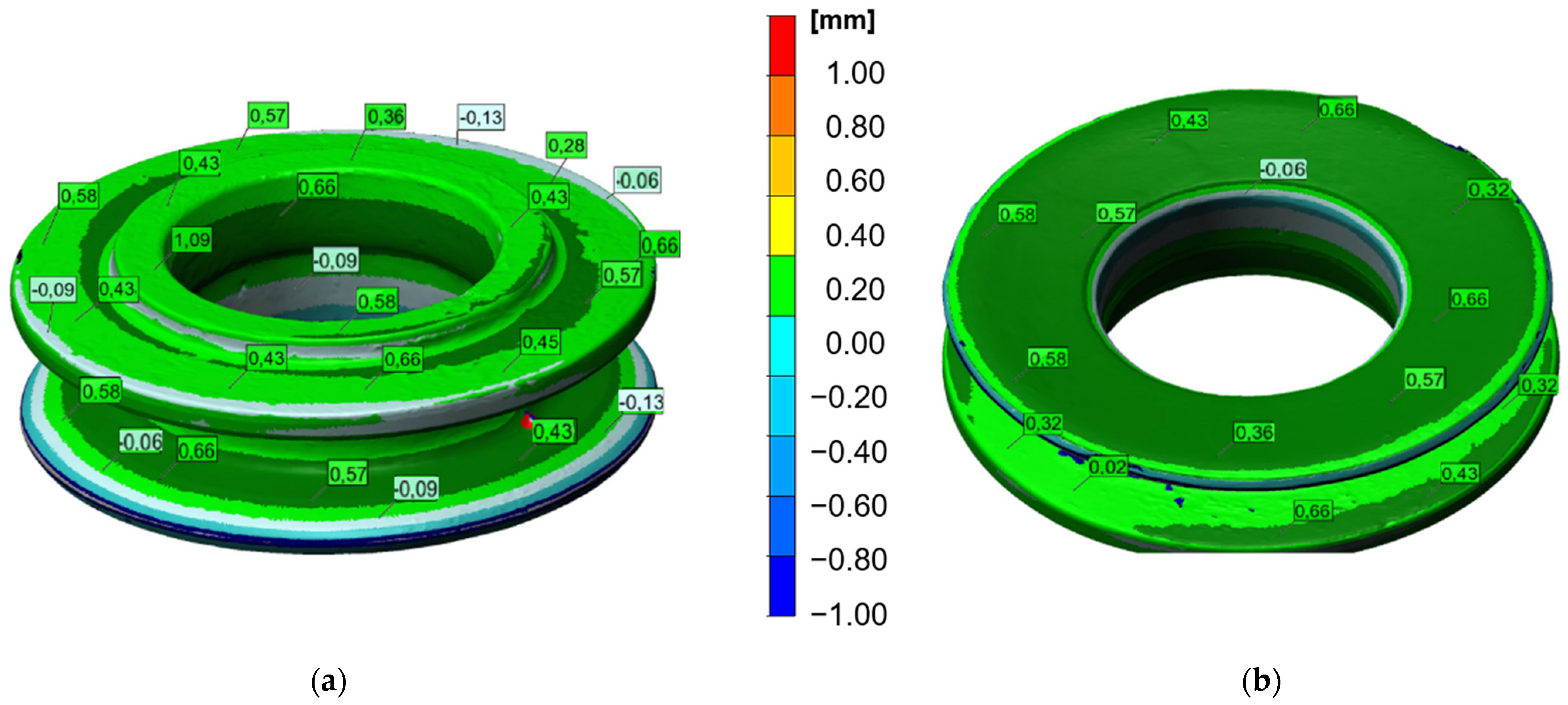
- Three-dimensional scanning Atos Core 135 structured light scanner (GOM, Braunschweig, Germany), equipped with two 5MPix CCD cameras (GOM, Braunschweig, Germany) for a single scan complex analysis of the forging process with the use of, e.g.,
- -
- Thermal imaging using a camera Flir 840 (FLIR Systems, Inc. Wilsonville, OR, USA), as well as a macroscopic analysis of the tools and the forging defects by means of a camera Cannon EOSx 60D (Cannon, Ōita, Japan).
- -
- Development of CAD models of a ready forging, as well as a tool by means of the program Catia V6R50 (Dassault Systèmes S.A.; Vélizy-Villacoublay, France)
- -
- Based on the above information, a numerical model was developed and simulations of the innovative technology of hot precision forging were carried out with the use of the calculation package of the Forge 3.0 NxT (Transvalor, Biot, France) program to determine the key parameters and physical quantities, as well as identify the most important problems.
- -
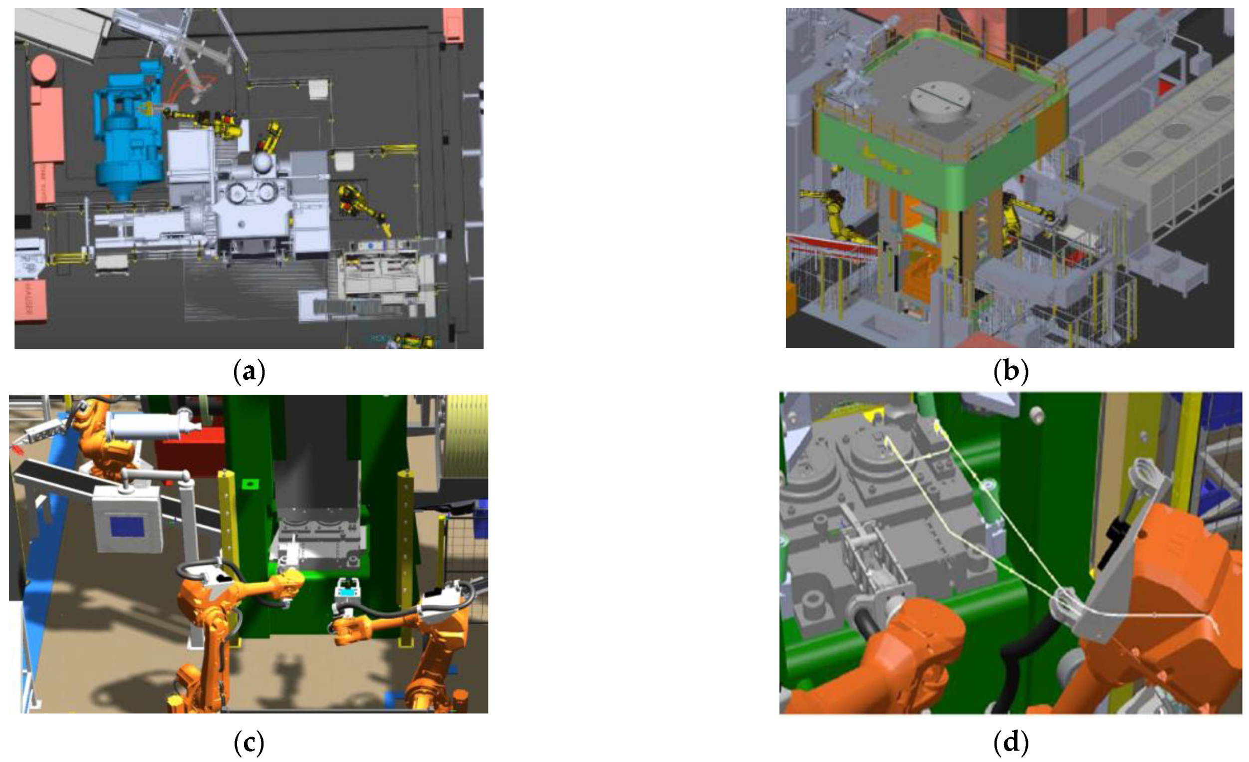
- Modelling of the position and trajectory of the robots’ movement (RobotSudion, ABB Group, Zurich, Switzerland).
- -
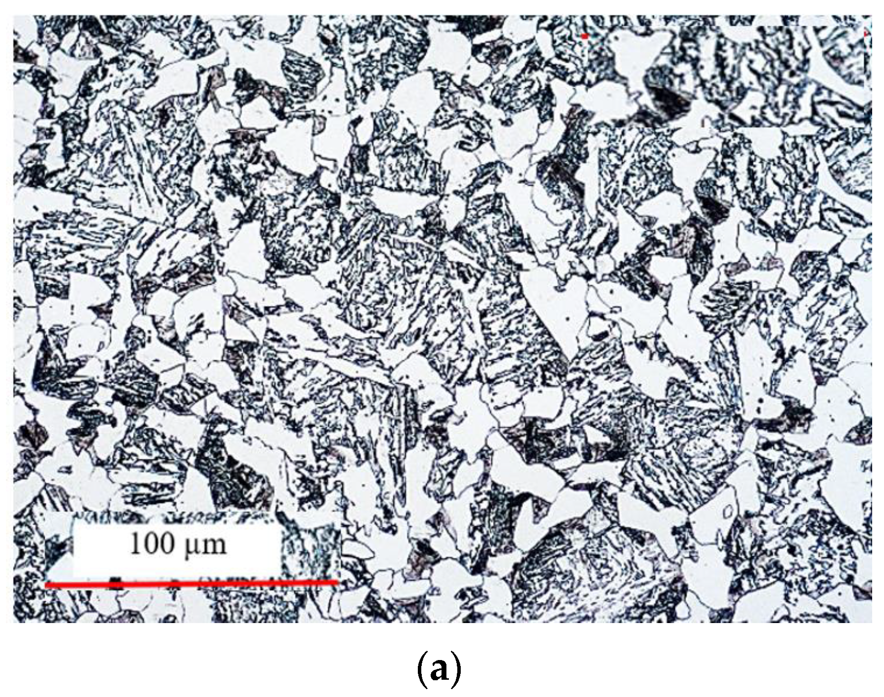
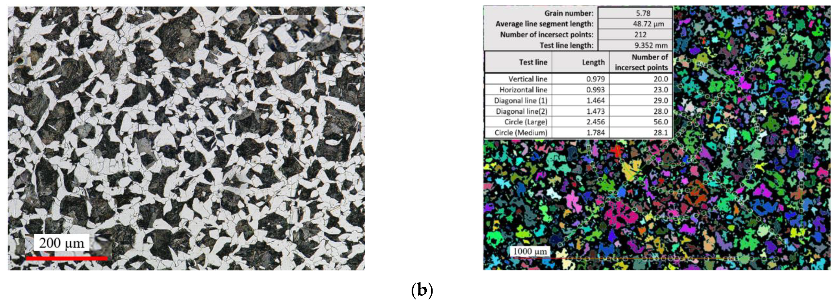
- Microstructural observations (for verification purposes) with the use of a Keyence VHX-6000 digital microscope (Keyence International, Mechelen, Belgium) The grinding and polishing, in order to obtain traditional micro-sections, were conducted on a grinder-polisher Struers 330 (Struers, Ballerup, Denmark). For the etching, a Nital 3% solution was used.
- -
- Hardness measurements, made using a hardness tester LECO LC140 (LECO, St. Joseph, MO, USA).
3. Development of an Innovative Technology—Results and Discussion
4. Verification of the Developed Solution
5. Conclusions
- -
- The development of an innovative technology was carried out using FE modelling with the additional consideration of the aspects of technology robotization.
- -
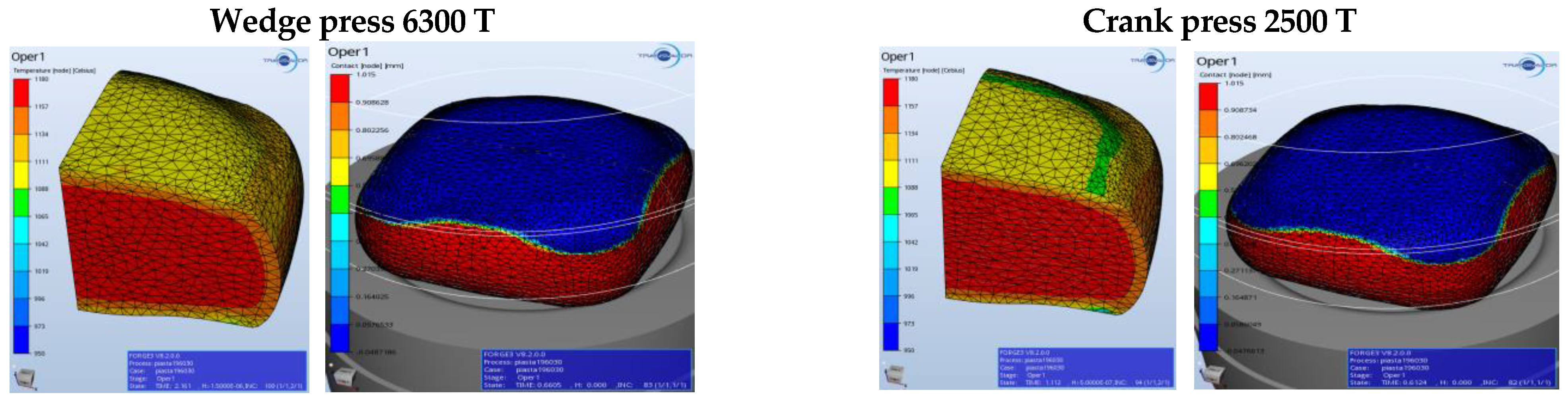
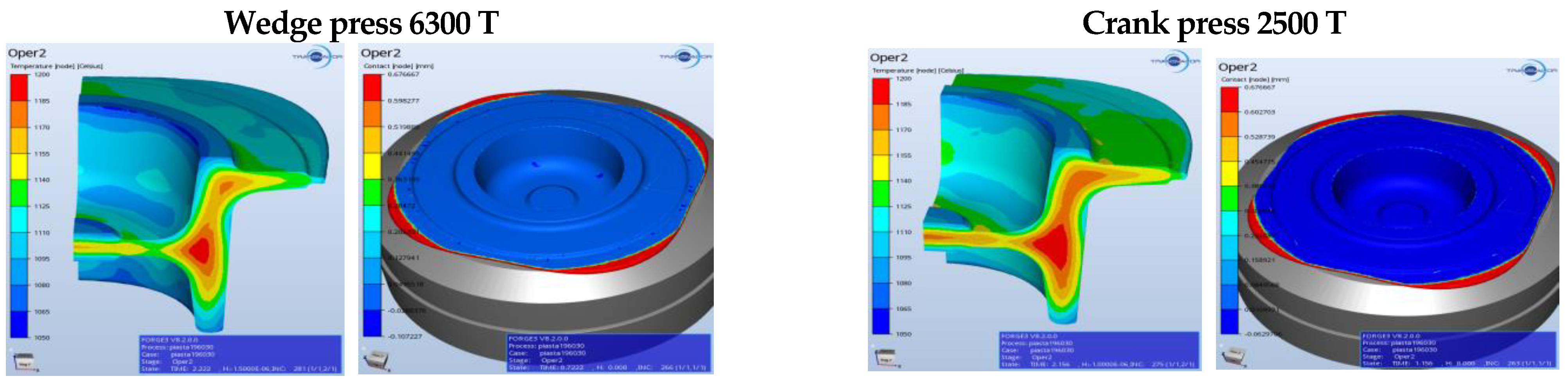
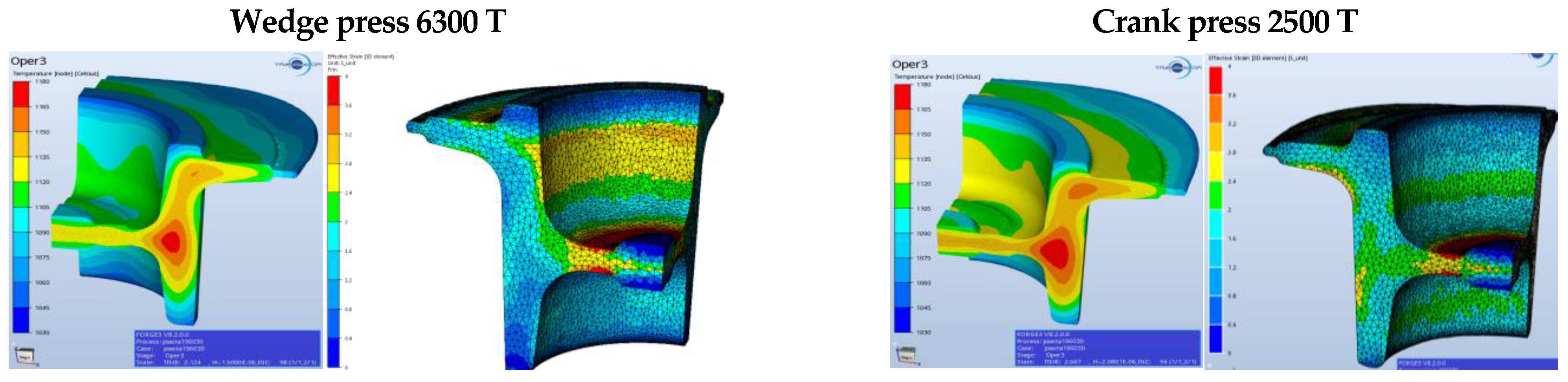
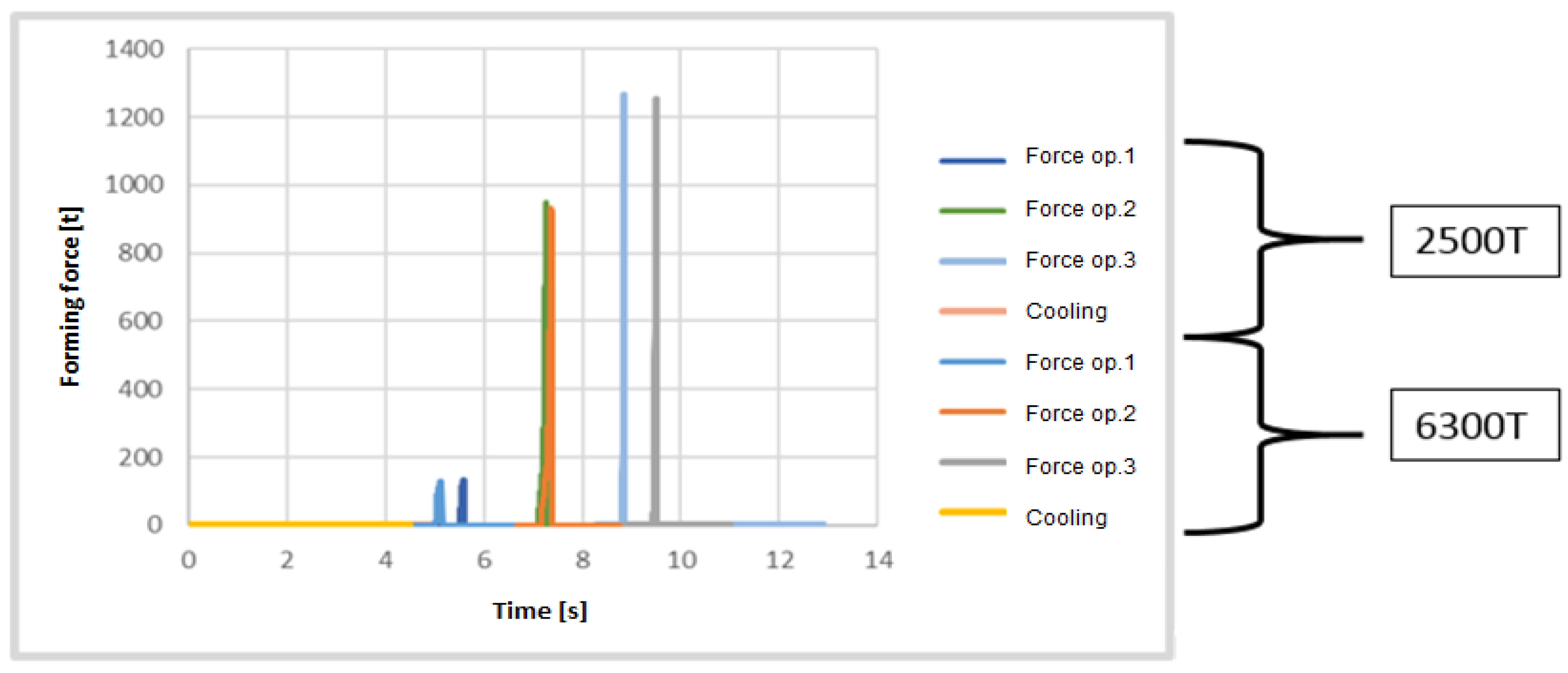
- The tests included multi-variant numerical simulations of the forging process by means of the computing package Forge 3.0 NxT, including a comparison of the possibilities of producing an element of a belt conveyor flight on two different forging aggregates: a wedge press and a crank press.
- -
- Due to the difficult-to-determine effect of the heat generated by the deformed material, as well as intensive friction, on the thermal capacity of the tools and their thermal resistance and hardness in the case of the wedge press, a decision was made that the optimal solution would be forging on a crank press.
- -
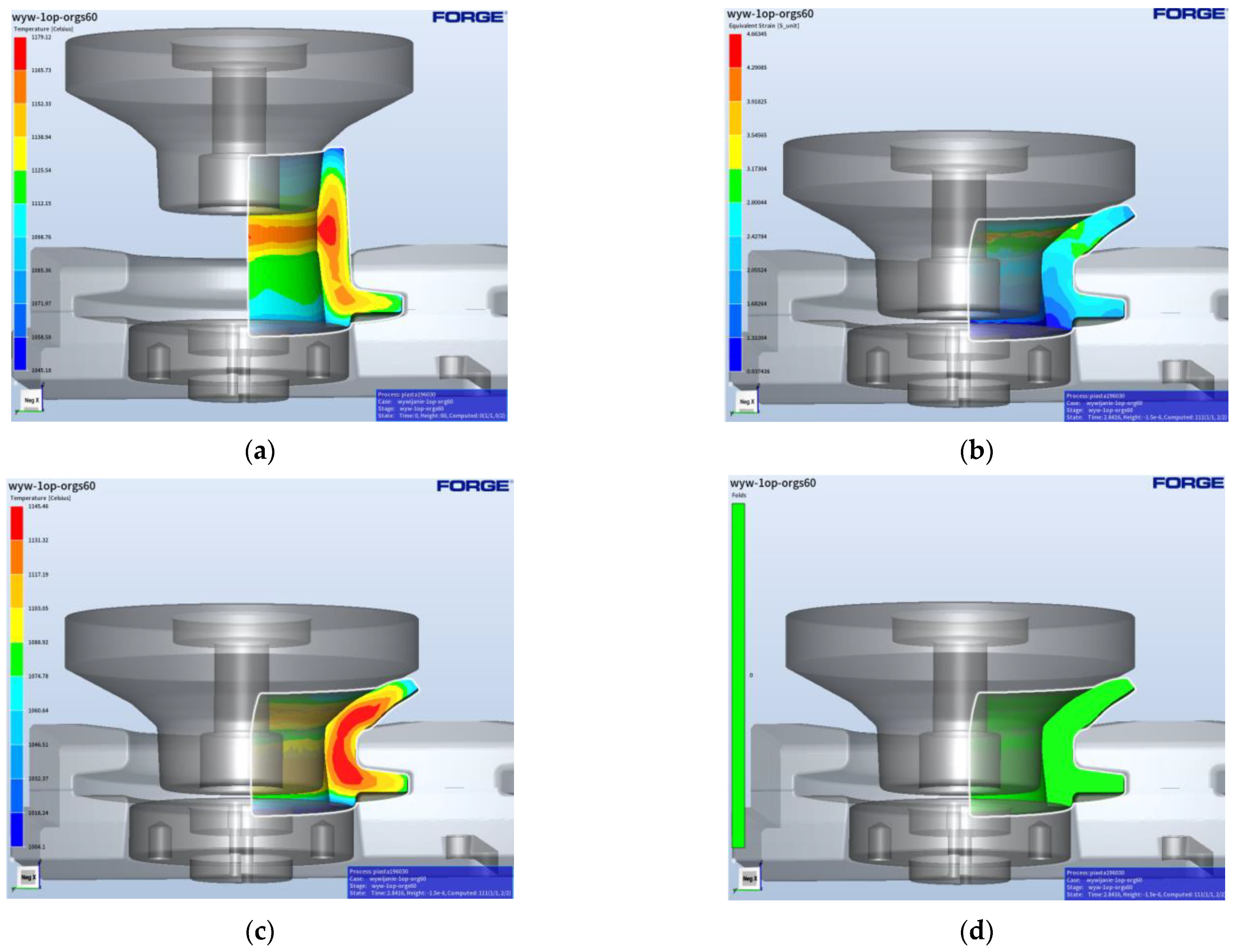
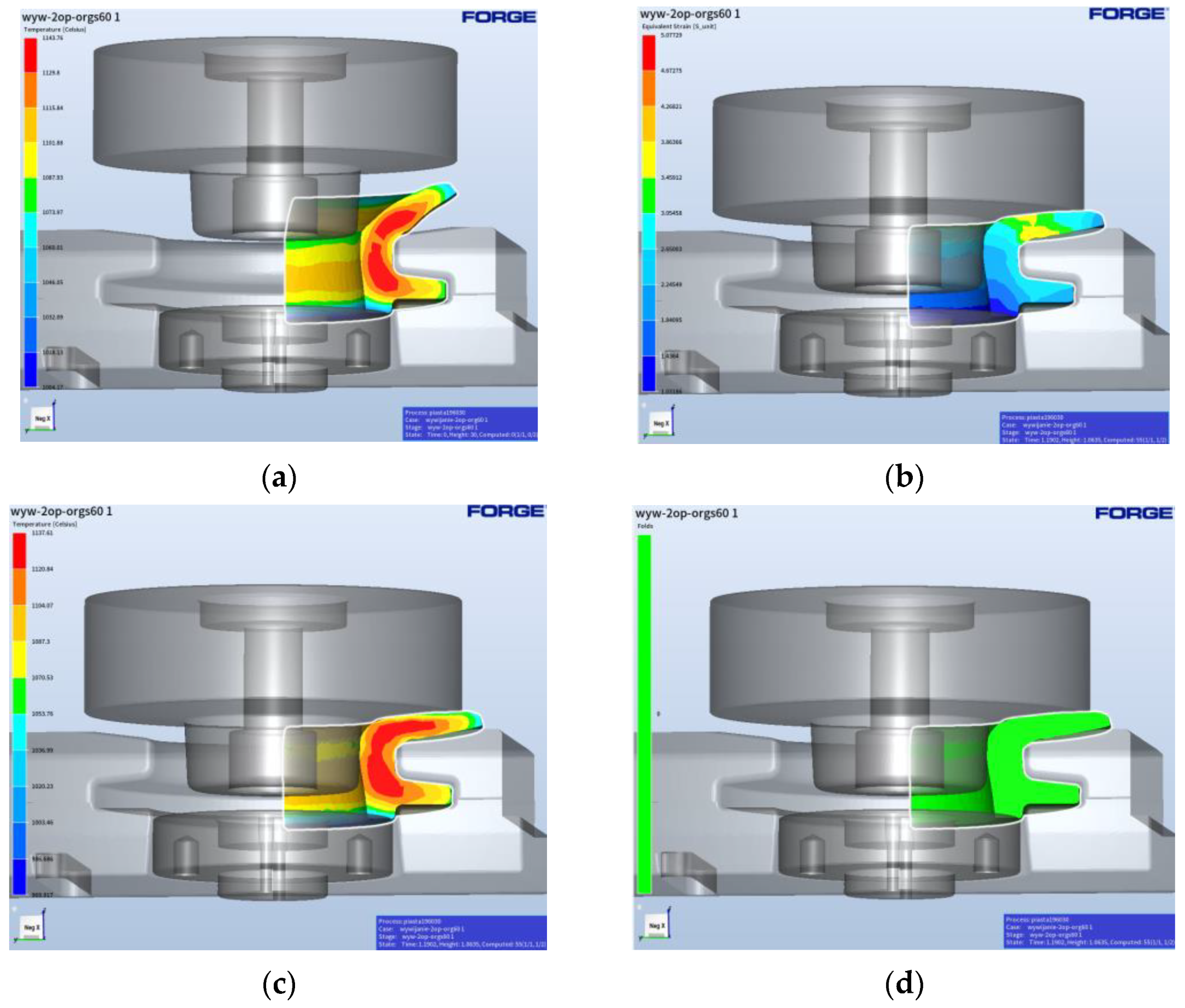
- Based on the authors’ own initial concept and the results of FEM modelling, a special device for forming flanges in a two-stage process was designed and developed, which has proven its worth in industrial forging conditions and is certainly new in terms of technology.
- -
- Based on the results obtained from the FEM simulations, developed CAD models and the generated G-codes, the designed metal tooling was made.
- -
- The developed technology was verified under industrial conditions on the existing elastic automatized forging seat, based on the ideology of Industry 4.0, and the obtained results were correlated with the proper dimensions and shape requirements.
- -
- The achieved results of the technological tests confirmed that the designed and implemented technology is correct. Both the accuracy of the tolerated dimensions and the geometry are in agreement with the requirements.
- -
- Introducing robotization into technological process was intended at making the existing process stable and repeatable, which would raise the quality of the forgings and, at the same time, reduce the rejection rate percentage, as a result of eliminating the errors made by the operator.
- -
- The performed studies referring to the technology, as well as the assessment and measurement of the obtained forgings and also hardness measurements and microstructure research, can establish that the developed technology, which was then verified on the constructed technological line, is correct.
Author Contributions
Funding
Institutional Review Board Statement
Informed Consent Statement
Data Availability Statement
Conflicts of Interest
References
- Zhao, H.; Qi, J.; Su, R.; Zhang, H.; Chen, H.; Bai, L.; Wang, C. Hot deformation behaviour of 40CrNi steel and evaluation of different processing map construction methods. J. Mater. Res. Technol. 2020, 9, 2856–2869. [Google Scholar] [CrossRef]
- Gronostajski, Z.; Hawryluk, M. The main aspects of precision forging. Arch. Civ. Mech. Eng. 2008, 8, 39–55. [Google Scholar] [CrossRef]
- Leite, J.R.; Cavalieri, D.C.; Prado, A.R. Efficient monitoring of longitudinal tears in conveyor belts using 2D laser scanner and statistical methods. Measurement 2024, 227, 114225. [Google Scholar] [CrossRef]
- Mallah, S.; Aloullal, A.; Kamach, O.; Masmoudi, M.; Kouiss, K.; Chebak, A. Modeling the Bulk Port Belt-Conveyor Routing Problem Considering Interactions with Storage Spaces and Loading Operations. IEEE Access 2023, 11, 87709–87731. [Google Scholar] [CrossRef]
- Andrejiova, M.; Grincova, A.; Marasova, D. Measurement and simulation of impact wear damage to industrial conveyor belts. Wear 2016, 368–369, 400–407. [Google Scholar] [CrossRef]
- Altan, T. Cold and Hot Forging Fundamentals and Application; ASM International: Geauga County, OH, USA, 2005. [Google Scholar]
- Han, Y.; Wang, M.; Du, M.; Guo, T. Research on deformation uniformity control of thin-walled conical aeroengine forgings based on GA-SVR. Int. J. Adv. Manuf. Technol. 2024, 131, 1211–1222. [Google Scholar] [CrossRef]
- Zharov, M.V.; Preobrazhenskii, E.V. Control of technological parameters in the process of ribbed panel forging: Use of measuring equipment and mathematical modeling methods. Meas. Tech. 2024, 66, 776–784. [Google Scholar] [CrossRef]
- Shotri, R.; Miura, T.; Geng, P.; Morisada, Y.; Ushioda, K.; Fujii, H. Probing joining mechanism of Ti6Al4V—SS316L steel rods in pressure-controlled joule-heat forge welding. J. Mater. Process. Technol. 2024, 326, 118315. [Google Scholar] [CrossRef]
- Kumar, R.R.; Babu, J.M.; Saleh, B.; Chandrashekar, A.; Saxena, K.K.; Deepak, A.; Razak, A.; Buradi, A.; Ketema, A. Investigation of friction welding parameters of AISI 304L/Ti-6AL-4V joints. Mater. Res. Express. 2022, 9, 106515. [Google Scholar] [CrossRef]
- Taraphdar, P.K.; Kumar, R.; Giri, A.; Pandey, C.; Mahapatra, M.M.; Sridhar, K. Residual stress distribution in thick double-V butt welds with varying groove configuration, restraints and mechanical tensioning. J. Manuf. Process. 2021, 68, 1405–1417. [Google Scholar] [CrossRef]
- Deng, D.; Murakawa, H. Numerical simulation of temperature field and residual stress in multi-pass welds in stainless steel pipe and comparison with experimental measurements. Comp. Mater. Sci. 2006, 37, 269–277. [Google Scholar] [CrossRef]
- Pelliccione, A.S.; Coelho, P.C.; Lopes, D.E.B.; Ennes, C.S.B.; Jambo, H.C.M.; Santanna, R. Failure analysis of a stainless steel socket-welding flange due to improper manufacturing process and chemical composition. Eng. Fail. Anal. 2020, 108, 104288. [Google Scholar] [CrossRef]
- Abid, M.; Qarni, M.J. Numerical Investigation of Residual Stresses and Distortions due to Multi-Pass Welding in a Pipe-Flange Joint. Proc. Inst. Mech. Eng. Part E J. Proc. Mech. Eng. 2010, 224, 253–267. [Google Scholar] [CrossRef]
- Abid, M.; Siddique, M. Numerical simulation of the effect of constraints on welding deformations and residual stresses in a pipe–flange joint. Model. Simul. Mater. Sci. Eng. 2005, 13, 919–933. [Google Scholar] [CrossRef]
- Internal Report. Library of the Faculty of Mechanical Engineering; Wroclaw University of Science and Technology: Wroclaw, Poland, 2023. [Google Scholar]
- Hawryluk, M. Review of selected methods of increasing the life of forging tools in hot die forging processes. Arch. Civ. Mech. Eng. 2016, 16, 845–866. [Google Scholar] [CrossRef]
- Sharma, S.; Sharma, M.; Gupta, V.; Singh, J. A Systematic Review of Factors Affecting the Process Parameters and Various Measurement Techniques in Forging Processes. Steel Res. Int. 2023, 94, 2200529. [Google Scholar] [CrossRef]
- Hawryluk, M.; Polak, S.; Rychlik, M.; Dudkiewicz, Ł.; Borowski, J.; Suliga, M. Possibilities of Measuring and Detecting Defects of Forged Parts in Die Hot-Forging Processes. Materials 2023, 17, 213. [Google Scholar] [CrossRef] [PubMed]
- Wojtaszek, M.; Lisiecki, Ł.; Łukaszek-Sołek, A.; Korpała, G.; Zyguła, K.; Śleboda, T.; Jabłońska, M.B.; Prahl, U. Application of processing maps and numerical modelling for identification of parameters and limitations of hot forging process of 80MnSi8-6 steel. Arch. Civ. Mech. Eng. 2023, 23, 240. [Google Scholar] [CrossRef]
- Mitchell, G.; Kramer, A. Forging Operations—Machine Forging, Forging Dies and Special Forging Operations; Read Books Ltd.: Redditch, UK, 2013. [Google Scholar]
- Jolgaf, M.; Hamouda, A.M.S.; Sulaiman, S.; Hamdan, M.M. Development of a CAD/CAM system for the closed-die forging process. J. Mater. Process. Technol. 2003, 138, 436–442. [Google Scholar] [CrossRef]
- Bonte, M.H.A.; Van Den Boogaard, A.H.; Huétink, J. An optimisation strategy for industrial metal forming processes: Modelling, screening and solving of optimisation problems in metal forming. Struct. Multidisc. Optim. 2008, 35, 571–586. [Google Scholar] [CrossRef]
- Ou, H.; Wang, P.; Lu, B.; Long, H. Finite element modelling and optimisation of net-shape metal forming processes with uncertainties. Comput. Struct. 2012, 90–91, 13–27. [Google Scholar] [CrossRef]
- Krishna, R.H.; Jena, D.P. Analytical and numerical modelling of open-die forging process for elliptical cross-section of billet. Measurement 2019, 134, 855–865. [Google Scholar] [CrossRef]
- Hawryluk, M.; Ziemba, J. Application of the 3D reverse scanning method in the analysis of tool wear and forging defects. Measurement 2018, 128, 204–213. [Google Scholar] [CrossRef]
- Lee, S.; Quagliato, L.; Park, D.; Kwon, I.; Sun, J.; Kim, N. A New Approach to Preform Design in Metal Forging Processes Based on the Convolution Neural Network. Appl. Sci. 2021, 11, 7948. [Google Scholar] [CrossRef]
- Li, S.Y.; Cheng, S.Y. Design Optimization for Cold Forging by an Integrated Methodology of CAD/FEM/ANN. Adv. Mater. Res. 2010, 97–101, 3281–3284. [Google Scholar] [CrossRef]
- Bouissa, Y.; Bohlooli, N.; Shahriari, D.; Champliaud, H.; Morin, J.-B.; Jahazi, M. FEM modeling and experimental validation of quench-induced distortions of large size steel forgings. J. Manuf. Process. 2020, 58, 592–605. [Google Scholar] [CrossRef]
- Xu, Y.; Zhang, Y.; Zhuang, X.; Cao, Z.; Lu, Y.; Zhao, Z. Numerical modeling and anvil design of high-speed forging process for railway axles. Int. J. Mater. Form. 2021, 14, 813–832. [Google Scholar] [CrossRef]
- Hawryluk, M.; Gronostajski, Z.; Jabłoński, P.; Janik, M.; Suliga, M. An integrated vision control system for the evaluation of the shape-dimensional accuracy and quality of valve forgings used in motor truck engines. Measurement 2023, 210, 112541. [Google Scholar] [CrossRef]
- Yin, G.; Zhu, Z.; Gong, H.; Lu, Z.; Yong, H.; Liu, L.; He, W. Flexible punching system using industrial robots for automotive panels. Rob. Comp. Integr. Manuf. 2018, 52, 92–99. [Google Scholar] [CrossRef]
- Liu, Y.; Wu, Y.; Wang, J.; Liu, S. Defect analysis and design optimization on the hot forging of automotive balance shaft based on 3D and 2D simulations. Int. J. Adv. Manuf. Technol. 2018, 94, 2739–2749. [Google Scholar] [CrossRef]
- Bałon, P.; Kiełbasa, B.; Kowalski, Ł.; Smusz, R. Case Study on the Influence of Forming Parameters on Complex Shape Part Deformation. Adv. Sci. Technol. Res. J. 2022, 16, 204–213. [Google Scholar] [CrossRef] [PubMed]
- Chakraborty, M.; Banerjee, N.; De, S. Analysis and optimization of die geometry for forging dies in railway wheel manufacturing. Int. J. Interact. Des. Manuf. 2023, 18, 2449–2465. [Google Scholar] [CrossRef]
- Hawryluk, M.; Ziemba, J.; Zwierzchowski, M.; Janik, M. Analysis of a forging die wear by 3D reverse scanning combined with SEM and hardness tests. Wear 2021, 476, 203749. [Google Scholar] [CrossRef]
- Pandya, V.A.; George, P.M. Effect of preform design on forging load and effective stress during closed die hot forging process of pin. Mater. Today Proc. 2021, 44, 106–112. [Google Scholar] [CrossRef]
- Ghaei, A.; Movahhedy, M.R. Die design for the radial forging process using 3D FEM. J. Mater. Process. Technol. 2007, 182, 534–539. [Google Scholar] [CrossRef]
- Hawryluk, M.; Rychlik, M. An implementation of robotization for the chosen hot die forging process. Arch. Civ. Mech. Eng. 2022, 22, 119. [Google Scholar] [CrossRef]
- Du, Z.; Xu, W.; Wang, Z.; Zhu, X.; Wang, J.; Wang, H. Multi-objective optimization of concave radial forging process parameters based on response surface methodology and genetic algorithm. Int. J. Adv. Manuf. Technol. 2023, 130, 5025–5044. [Google Scholar] [CrossRef]
- Zhang, L.; Yang, W.; Cheng, Q.; Wang, H.; Zheng, S.; Li, M.; Duan, Y.; Xu, Z.; Xi, Y. The effect of different forging ratios on the properties and microstructures of high strength steel 40CrNi2Si2MoV. J. Mater. Res. Technol. 2024, 29, 2326–2338. [Google Scholar] [CrossRef]
- Wang, Z.; Jiang, C.; Wei, B.; Wang, Y. Numerical Simulation and Process Parameter Optimization of Warm Forging Near-Net Forming for Spiral Bevel Gear. Appl. Sci. 2024, 14, 1147. [Google Scholar] [CrossRef]
- Xu, S.; Lin, Y.; Shan, D. Application of intelligent decision system based on artifcial neural network in free forging of the engine main shaft. Int. J. Adv. Manuf. Technol. 2024. [Google Scholar] [CrossRef]
- Hawryluk, M.; Dudkiewicz, Ł.; Polak, S.; Barełkowski, A.; Miżejewski, A.; Szymańska, T. Improvement of the Technology of Precision Forging of Connecting Rod-Type Forgings in a Multiple System, in the Aspect of the Possibilities of Process Robotization by Means of Numerical Modeling. Materials 2024, 17, 1087. [Google Scholar] [CrossRef] [PubMed]
- ISO 643:2020; Steels—Micrographic Determination of the Apparent Grain Size. International Organization for Standardization: Geneva, Switzerland, 2020.


| No. | Operation | Time [s] | Aggregate |
|---|---|---|---|
| 1 | Heating | 160 | Induction heater |
| 2 | Transport to the press | 5/4.5 | Feeder + robot |
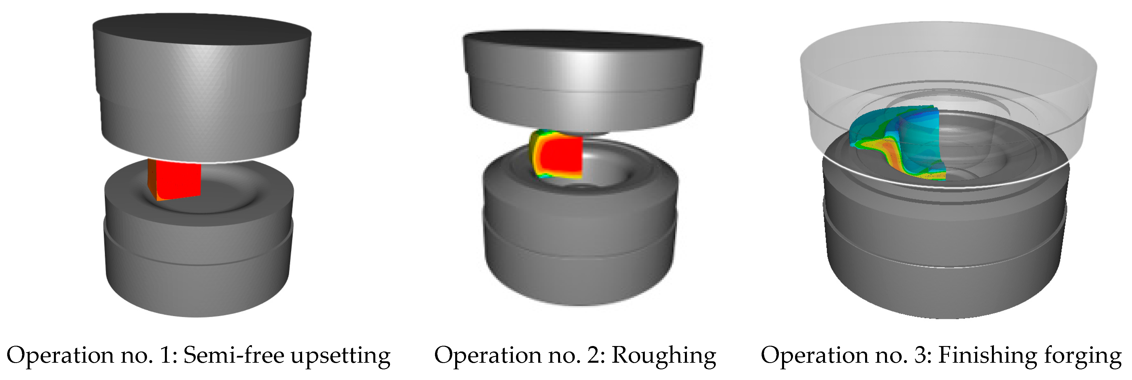
| 3 | Upsetting | 1/1.5 | Wedge press/crank press |
| 4 | Transfer | 1.5/2 | (walking beam) |
| 5 | Roughing | 1/1.5 | Wedge press/crank press |
| 6 | Transfer | 2 | (walking beam) |
| 7 | Finishing forging | 1/1.5 | Wedge press/crank press |
| 8 | Transfer | 2 | (walking beam) |
| 9 | Trimming | 1.5 | Hydraulic press 1000 T |
| 10 | Transport to the press | 5 | Robot |
| 11 | Punching | 4 | Hydraulic press 2000 T |
| 12 | Relocation | 3 | Robot |
| 13 | Preliminary flanging | 4 | Hydraulic press 2000 T |
| 14 | Relocation | 3 | Robot |
| 15 | Finishing flanging | 4 | Hydraulic press 2000 T |
Disclaimer/Publisher’s Note: The statements, opinions and data contained in all publications are solely those of the individual author(s) and contributor(s) and not of MDPI and/or the editor(s). MDPI and/or the editor(s) disclaim responsibility for any injury to people or property resulting from any ideas, methods, instructions or products referred to in the content. |
© 2024 by the authors. Licensee MDPI, Basel, Switzerland. This article is an open access article distributed under the terms and conditions of the Creative Commons Attribution (CC BY) license (https://creativecommons.org/licenses/by/4.0/).
Share and Cite
Hawryluk, M.; Polak, S.; Rychlik, M.; Barełkowski, A.; Jakuć, J.; Marzec, J. Development and Implementation of Die Forging Technology Eliminating Flange Welding Operations in Conveyor Driver Forging. Materials 2024, 17, 3281. https://doi.org/10.3390/ma17133281
Hawryluk M, Polak S, Rychlik M, Barełkowski A, Jakuć J, Marzec J. Development and Implementation of Die Forging Technology Eliminating Flange Welding Operations in Conveyor Driver Forging. Materials. 2024; 17(13):3281. https://doi.org/10.3390/ma17133281
Chicago/Turabian StyleHawryluk, Marek, Sławomir Polak, Marcin Rychlik, Artur Barełkowski, Jakub Jakuć, and Jan Marzec. 2024. "Development and Implementation of Die Forging Technology Eliminating Flange Welding Operations in Conveyor Driver Forging" Materials 17, no. 13: 3281. https://doi.org/10.3390/ma17133281