
Surface Treatment Strategies and Their Impact on the Material Behavior and Interfacial Adhesion Strength of Shape Memory Alloy NiTi Wire Integrated in Glass Fiber-Reinforced Polymer Laminate Structures

 , , , ,
Abstract
:1. Introduction
2. Materials and Methods
2.1. Materials
2.2. Surface Treatment Methodologies on NiTi Wires
2.2.1. Thermal Treatments
2.2.2. Plasma Treatments
2.2.3. Chemical Treatments and Coatings
2.3. Hot-Press Molding
2.4. Characterization Techniques
2.4.1. Tensile Testing of Wires
2.4.2. Surface Analyses of Wires
2.4.3. Wire Pull-Out Tests
2.4.4. XRD Analyses
3. Results and Discussions
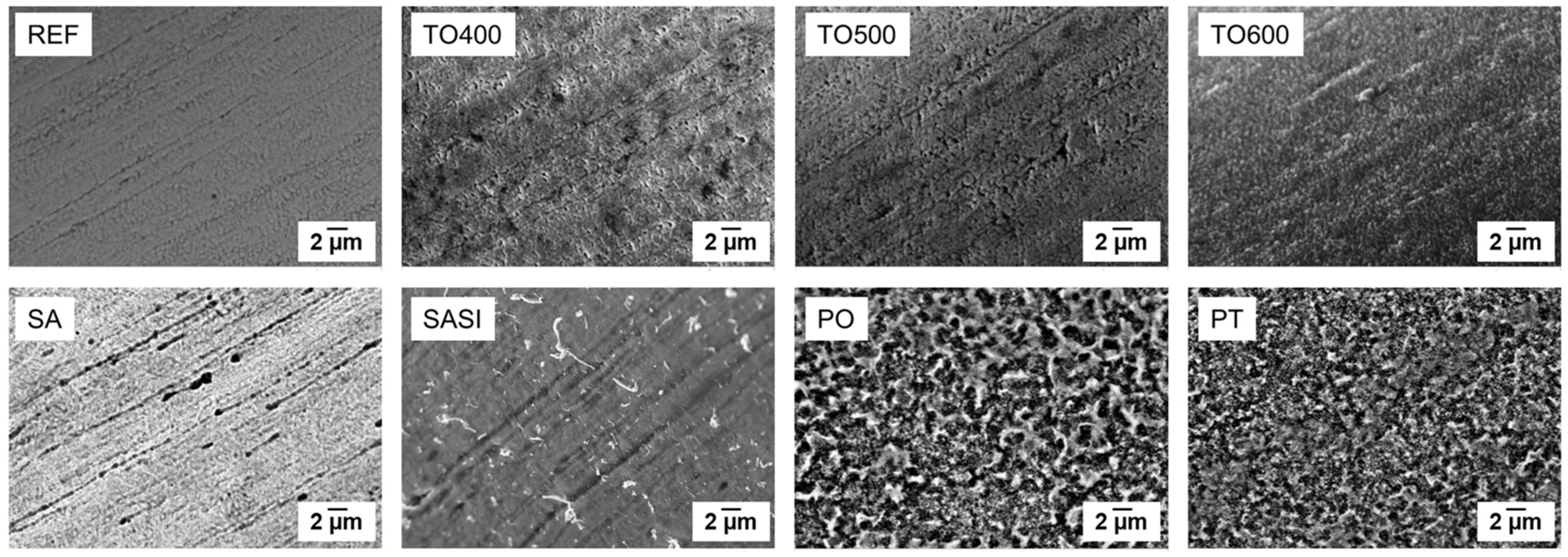
3.1. Surface Topography Characterization
3.1.1. SEM Analyses
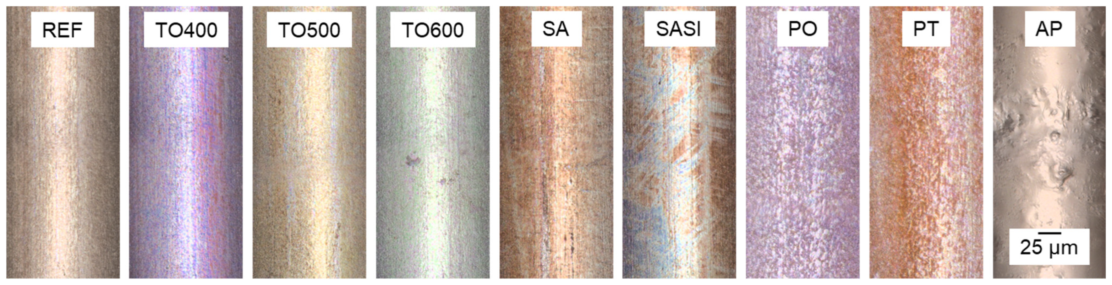
3.1.2. LSM Analyses
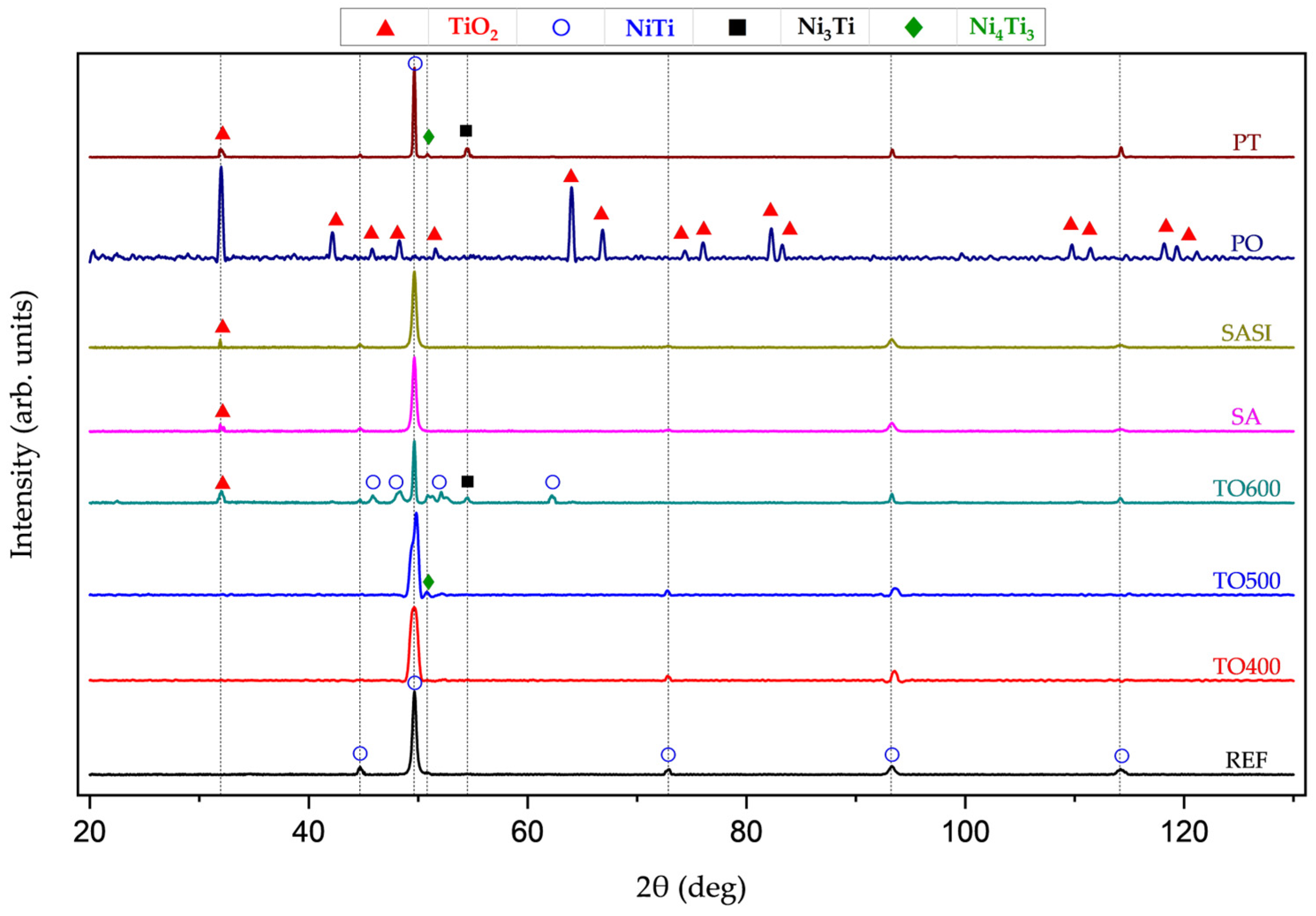
3.2. Material Characterization
XRD
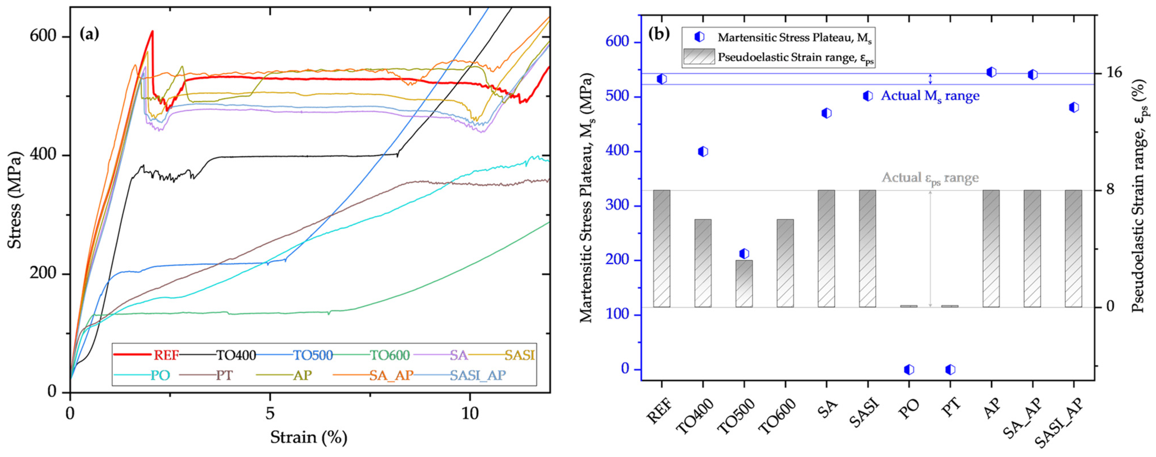
3.3. Mechanical Characterization
3.3.1. Tensile Testing Results
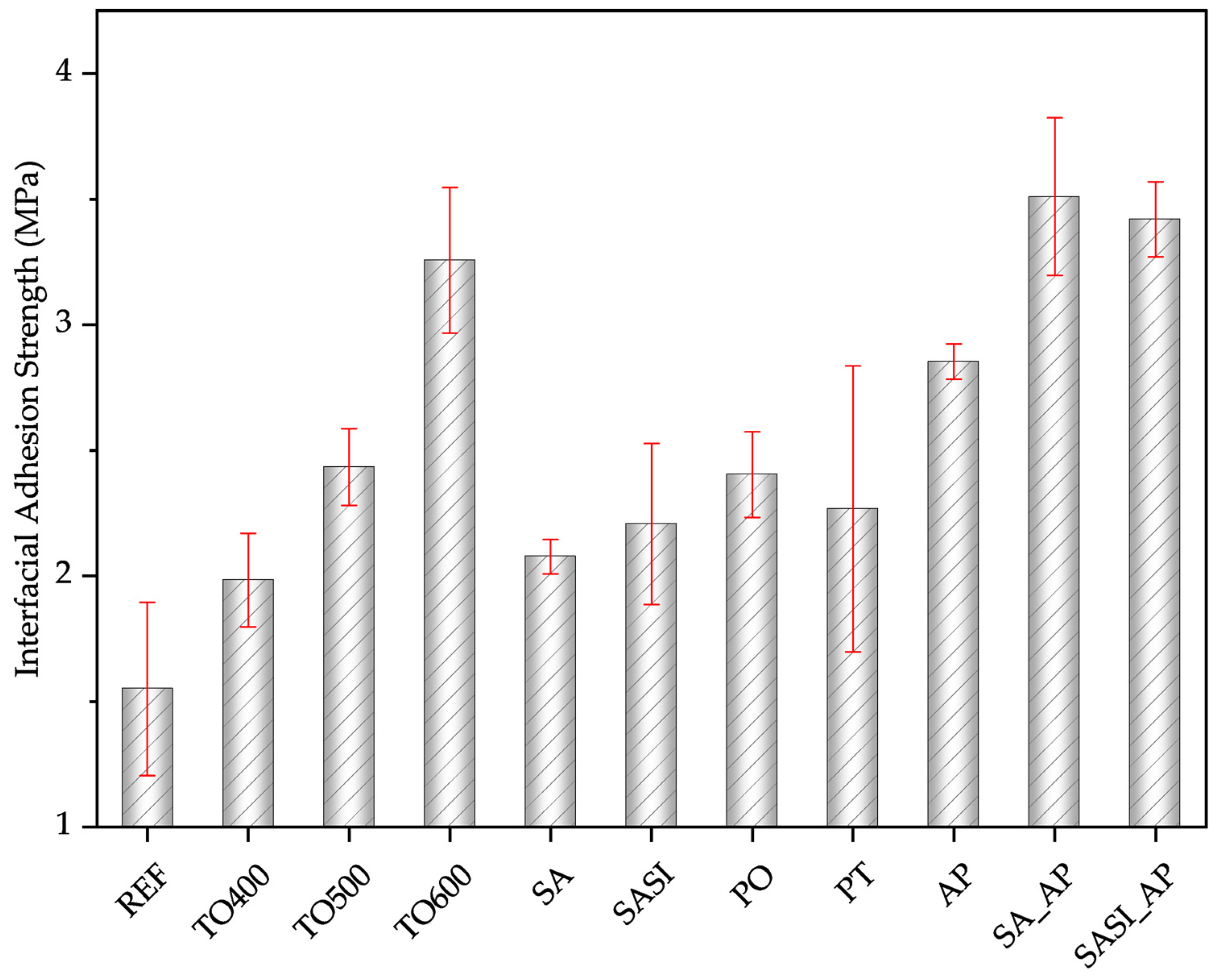
3.3.2. Single-Wire Pullout Test Analyses
4. Conclusions
Author Contributions
Funding
Institutional Review Board Statement
Informed Consent Statement
Data Availability Statement
Acknowledgments
Conflicts of Interest
References
- Duerig, T.W.; Melton, K.N.; Stöckel, D. Engineering Aspects of Shape Memory Alloys; Butterworth-Heinemann: Oxford, UK, 2013. [Google Scholar]
- Castleman, L.S.; Motzkin, S.M.; Alicandri, F.P.; Bonawit, V.L.; Johnson, A.A. Biocompatibility of nitinol alloy as an implant material. J. Biomed. Mater. Res. 1976, 10, 695–731. [Google Scholar] [CrossRef]
- Ramsden, J.; Allen, D.; Stephenson, D.; Alcock, J.; Peggs, G.; Fuller, G.; Goch, G. The design and manufacture of biomedical surfaces. CIRP Ann. 2007, 56, 687–711. [Google Scholar] [CrossRef]
- Jani, J.M.; Leary, M.; Subic, A. Shape memory alloys in automotive applications. Appl. Mech. Mater. 2014, 663, 248–253. [Google Scholar] [CrossRef]
- Huber, J.E.; Fleck, N.A.; Ashby, M.F. The selection of mechanical actuators based on performance indices. Proceedings of the Royal Society of London. Ser. A Math. Phys. Eng. Sci. 1997, 453, 2185–2205. [Google Scholar] [CrossRef]
- Straub, T.; Fell, J.; Zabler, S.; Gustmann, T.; Korn, H.; Fischer, S.C.L. Characterization of Filigree Additively Manufactured NiTi Structures Using Micro Tomography and Micromechanical Testing for Metamaterial Material Models. Materials 2023, 16, 676. [Google Scholar] [CrossRef] [PubMed]
- Boller, C. Integrating shape memory alloys into composite materials: Structural optimization and its implications on lightweight design. In Smart Materials, Structures, and Systems; SPIE: Bellingham, WA, USA, 2003; Volume 5062, pp. 1–9. [Google Scholar]
- Yuan, G.; Bai, Y.; Jia, Z.; Hui, D.; Lau, K.-T. Enhancement of interfacial bonding strength of SMA smart composites by using mechanical indented method. Compos. Part B Eng. 2016, 106, 99–106. [Google Scholar] [CrossRef]
- Bechtel, S.; Meisberger, M.; Klein, S.; Heib, T.; Quirin, S.; Herrmann, H.-G. Estimation of the Adhesion Interface Performance in Aluminum-PLA Joints by Thermographic Monitoring of the Material Extrusion Process. Materials 2020, 13, 3371. [Google Scholar] [CrossRef] [PubMed]
- Lincon, M.I.; Hwang, H.-Y. Interfacial behaviors of shape-memory fibers embedded in epoxy adhesive. Compos. Struct. 2021, 275, 114413. [Google Scholar] [CrossRef]
- Samal, S.; Tyc, O.; Heller, L.; Šittner, P.; Malik, M.; Poddar, P.; Catauro, M.; Blanco, I. Study of interfacial adhesion between nickel-titanium shape memory alloy and a polymer matrix by laser surface pattern. Appl. Sci. 2020, 10, 2172. [Google Scholar] [CrossRef]
- Samal, S.; Heller, L.; Brajer, J.; Tyc, O.; Kadrevek, L.; Sittner, P. Laser annealing on the surface treatment of thin super elastic NiTi wire. IOP Conf. Ser. Mater. Sci. Eng. 2018, 362, 012007. [Google Scholar] [CrossRef]
- Yang, B.; Zhang, Y.; Xuan, F.-Z.; Xiao, B.; He, L.; Gao, Y. Improved adhesion between nickel–titanium SMA and polymer matrix via acid treatment and nano-silica particles coating. Adv. Compos. Mater. 2018, 27, 331–348. [Google Scholar] [CrossRef]
- Zhao, L.-M.; Feng, X.; Mi, X.-J.; Li, Y.-F.; Xie, H.-F.; Yin, X.-Q. The interfacial strength improvement of SMA composite using ZnO with electrochemical deposition method. Appl. Surf. Sci. 2014, 320, 670–673. [Google Scholar] [CrossRef]
- Lau, K.-T.; Tam, W.-Y.; Meng, X.-L.; Zhou, L.-M. Morphological study on twisted NiTi wires for smart composite systems. Mater. Lett. 2002, 57, 364–368. [Google Scholar] [CrossRef]
- Wang, Y.L.; Wang, Z.Q.; Zhou, L.M.; Huang, H.T. Influence of silane coupling agent on interfacial strength of SMA composite. Adv. Mater. Res. 2011, 143, 933–937. [Google Scholar] [CrossRef]
- Sadrnezhaad, S.K.; Nemati, N.H.; Bagheri, R. Improved adhesion of NiTi wire to silicone matrix for smart composite medical applications. Mater. Des. 2009, 30, 3667–3672. [Google Scholar] [CrossRef]
- Jonnalagadda, K.; Kline, G.E.; Sottos, N.R. Local displacements and load transfer in shape memory alloy composites. Exp. Mech. 1997, 37, 78–86. [Google Scholar] [CrossRef]
- Smith, N.; Antoun, G.; Ellis, A.; Crone, W. Improved adhesion between nickel–titanium shape memory alloy and a polymer matrix via silane coupling agents. Compos. Part A Appl. Sci. Manuf. 2004, 35, 1307–1312. [Google Scholar] [CrossRef]
- ASTM F2516-22; Standard Test Method for Tension Testing of Nickel-Titanium Superelastic Materials. ASTM International: West Conshohocken, PA, USA, 2022. [CrossRef]
- Fibre-Reinforced Composites—Measurement of Interfacial Shear Strength by Means of a Micromechanical Single-Fibre Pull-Out Test, DIN Media, 2022. Available online: https://www.dinmedia.de/de/technische-regel/din-spec-19289/356170553 (accessed on 10 July 2024).
- Zhu, L.; Fino, J.M.; Pelton, A.R. Oxidation of nitinol. In Proceedings of the International Conference on Shape memory and Superelastic Technologies, Pacific Grove, CA, USA, 5–8 May 2003; pp. 357–366. [Google Scholar]
- Firstov, G.; Vitchev, R.; Kumar, H.; Blanpain, B.; Van Humbeeck, J. Surface oxidation of NiTi shape memory alloy. Biomaterials 2002, 23, 4863–4871. [Google Scholar] [CrossRef] [PubMed]
- Hamdan, S.A.; Ibrahim, I.M.; Ali, I.M. Comparison of anatase and rutile tio2 nanostructure for gas sensing application. Dig. J. Nanomater. Biostruct. 2020, 15, 1001–1008. [Google Scholar] [CrossRef]
- Dawood, N.M.; Ali, E.L. The effects of chemical oxidation on corrosion behavior of NiTi alloy. IOP Conf. Ser. Mater. Sci. Eng. 2021, 1094, 012160. [Google Scholar] [CrossRef]
- Jani, J.M.; Leary, M.; Subic, A.; Gibson, M.A. A review of shape memory alloy research, applications and opportunities. Mater. Des. 2014, 56, 1078–1113. [Google Scholar] [CrossRef]
- Abavisani, I.; Rezaifar, O.; Kheyroddin, A. Multifunctional properties of shape memory materials in civil engineering applications: A state-of-the-art review. J. Build. Eng. 2021, 44, 102657. [Google Scholar] [CrossRef]
- Dong, X.; Fei, Y.; Wang, J.; Su, Y.; Jing, F.; Leng, Y.; Huang, N. Deformation behavior of tio2 films deposited on NiTi shape memory alloy after tensile and water-bath heating tests. Surf. Coat. Technol. 2021, 416, 127151. [Google Scholar] [CrossRef]
- Zhou, N.; Shen, C.; Wagner, M.-X.; Eggeler, G.; Mills, M.; Wang, Y. Effect of Ni4Ti3 precipitation on martensitic transformation in Ti-Ni. Acta Mater. 2010, 58, 6685–6694. [Google Scholar] [CrossRef]
- Jiang, S.-Y.; Zhang, Y.-Q.; Zhao, Y.-N.; Liu, S.-W.; Hu, L.; Zhao, C.-Z. Influence of Ni4Ti3 precipitates on phase transformation of NiTi shape memory alloy. Trans. Nonferrous Met. Soc. China 2015, 25, 4063–4071. [Google Scholar] [CrossRef]


| Sample ID | Surface Treatment Type | Materials Used | Temperature |
|---|---|---|---|
| - | - | - | (°C) |
| REF | Non-treated reference | - | - |
| TO400 | Thermal treatment | - | 400 |
| TO500 | - | 500 | |
| TO600 | - | 600 | |
| SA | Chemical treatment | 25% NH4OH; 30% H2O2; 5M NaOH | 60 |
| SASI | GPTMS; Xylene | 120 | |
| PO | Plasma treatment | - | 380 |
| PT | - | 380 | |
| AP | Adhesion Promoter coating | VESTAMELT® Hylink copolyamide | 200 |
| SA_AP | 200 | ||
| SASI_AP | 200 |
Disclaimer/Publisher’s Note: The statements, opinions and data contained in all publications are solely those of the individual author(s) and contributor(s) and not of MDPI and/or the editor(s). MDPI and/or the editor(s) disclaim responsibility for any injury to people or property resulting from any ideas, methods, instructions or products referred to in the content. |
© 2024 by the authors. Licensee MDPI, Basel, Switzerland. This article is an open access article distributed under the terms and conditions of the Creative Commons Attribution (CC BY) license (https://creativecommons.org/licenses/by/4.0/).
Share and Cite
Palaniyappan, S.; Ramesha, H.K.; Trautmann, M.; Quirin, S.; Heib, T.; Herrmann, H.-G.; Wagner, G. Surface Treatment Strategies and Their Impact on the Material Behavior and Interfacial Adhesion Strength of Shape Memory Alloy NiTi Wire Integrated in Glass Fiber-Reinforced Polymer Laminate Structures. Materials 2024, 17, 3513. https://doi.org/10.3390/ma17143513
Palaniyappan S, Ramesha HK, Trautmann M, Quirin S, Heib T, Herrmann H-G, Wagner G. Surface Treatment Strategies and Their Impact on the Material Behavior and Interfacial Adhesion Strength of Shape Memory Alloy NiTi Wire Integrated in Glass Fiber-Reinforced Polymer Laminate Structures. Materials. 2024; 17(14):3513. https://doi.org/10.3390/ma17143513
Chicago/Turabian StylePalaniyappan, Saravanan, Harshan Kalenahalli Ramesha, Maik Trautmann, Steven Quirin, Tobias Heib, Hans-Georg Herrmann, and Guntram Wagner. 2024. "Surface Treatment Strategies and Their Impact on the Material Behavior and Interfacial Adhesion Strength of Shape Memory Alloy NiTi Wire Integrated in Glass Fiber-Reinforced Polymer Laminate Structures" Materials 17, no. 14: 3513. https://doi.org/10.3390/ma17143513
APA StylePalaniyappan, S., Ramesha, H. K., Trautmann, M., Quirin, S., Heib, T., Herrmann, H.-G., & Wagner, G. (2024). Surface Treatment Strategies and Their Impact on the Material Behavior and Interfacial Adhesion Strength of Shape Memory Alloy NiTi Wire Integrated in Glass Fiber-Reinforced Polymer Laminate Structures. Materials, 17(14), 3513. https://doi.org/10.3390/ma17143513