
Wear Mechanisms of the Working Surface of Gears after Scuffing Tests

 , , and
Abstract
:1. Introduction
2. Materials and Methods
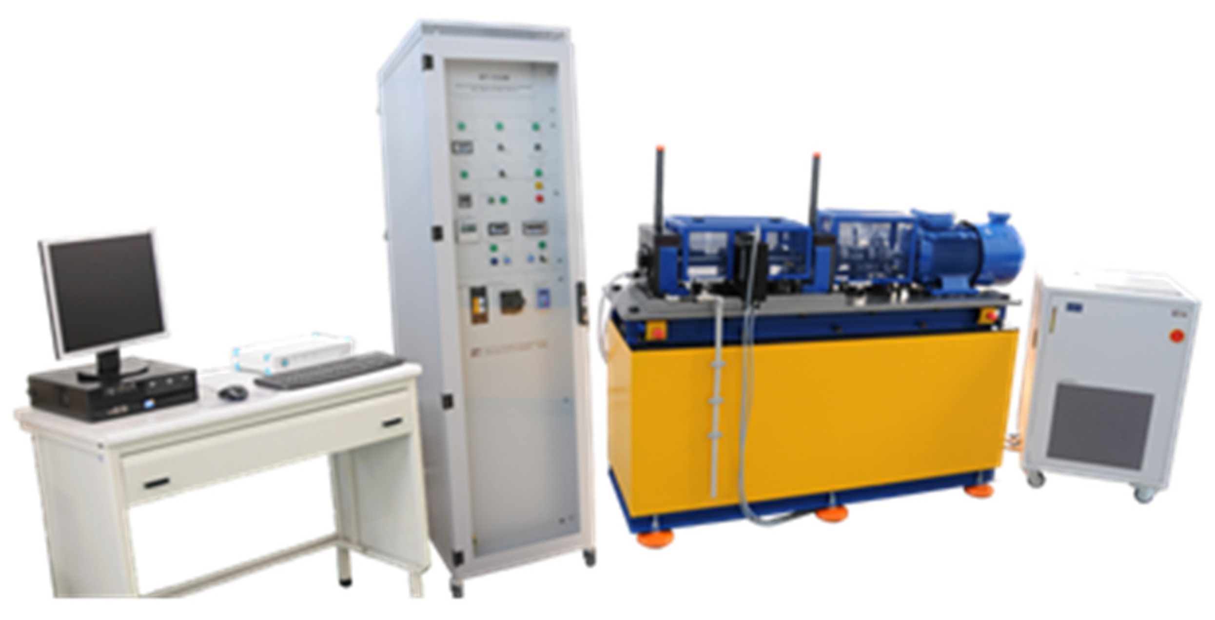
Scuffing Tests
| -engine rotational speed | 3000 rpm |
| -rolling speed | 16.6 m/s |
| -min. and max. load stage | from 1 to 10 |
| -torque load | from 3 to 373 Nm, changed gradually |
| -Hertz pressure on the small gear (pinion) | from 0.2 to 2.2 GPa |
| -initial test oil temperature | 90 °C (not stabilised during tests) |
| -type of lubrication | immersion |
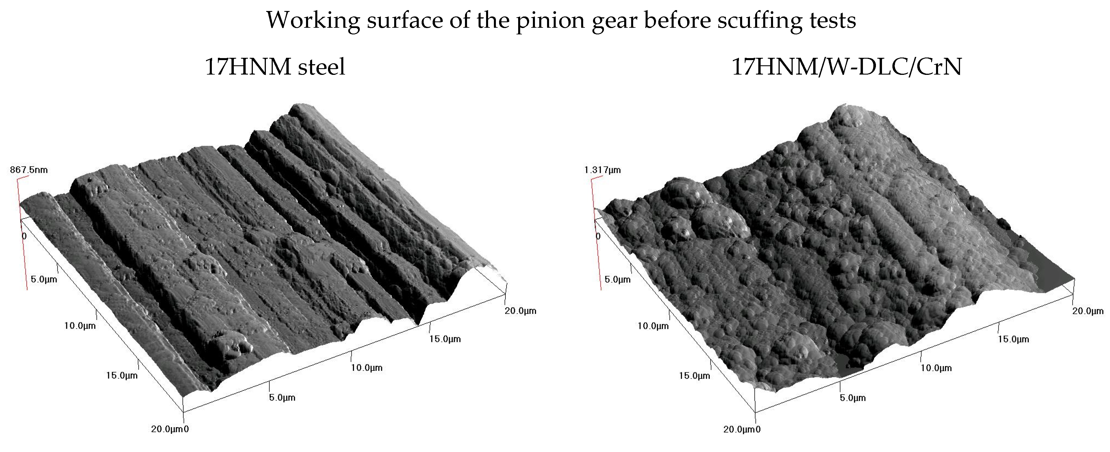
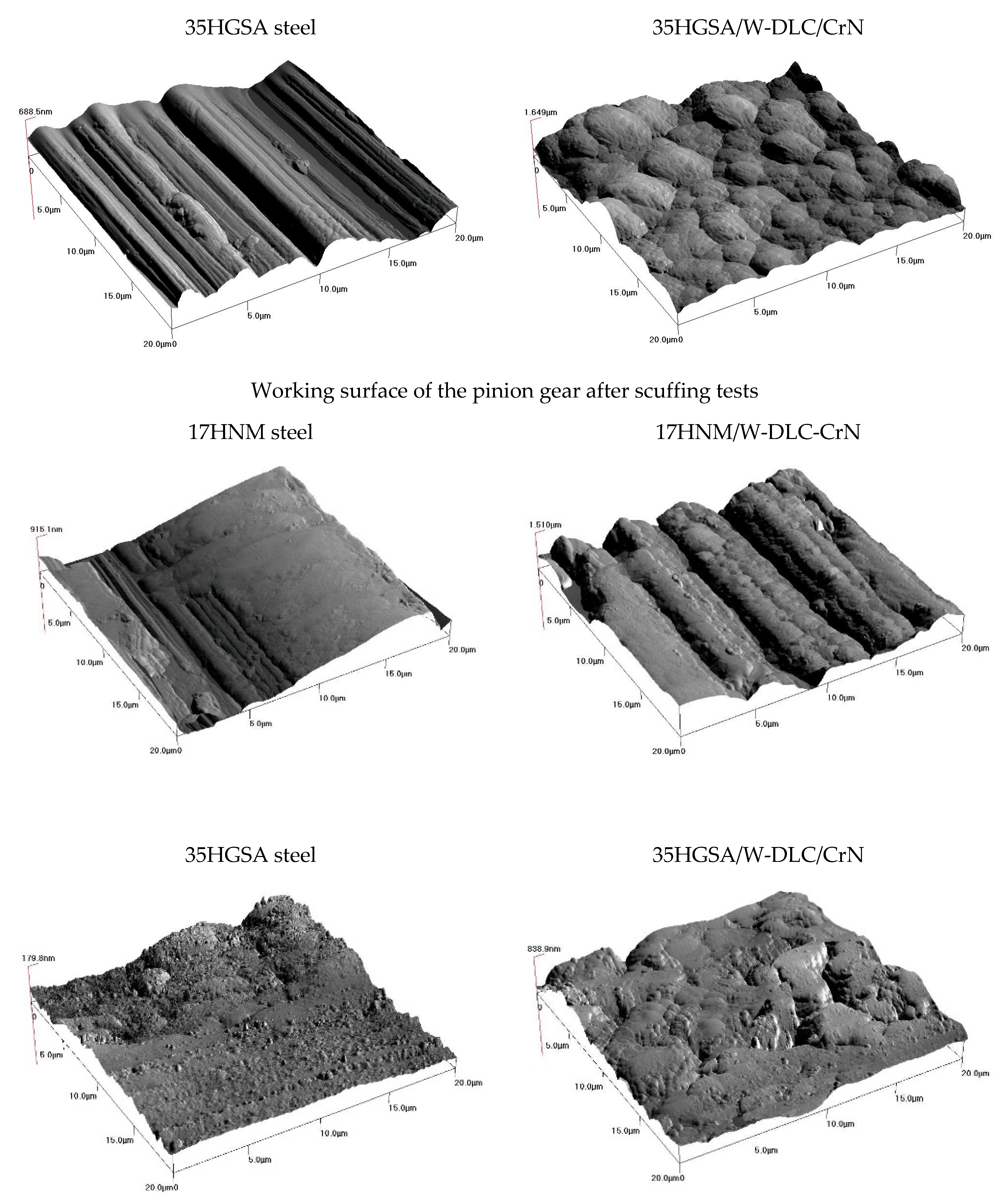
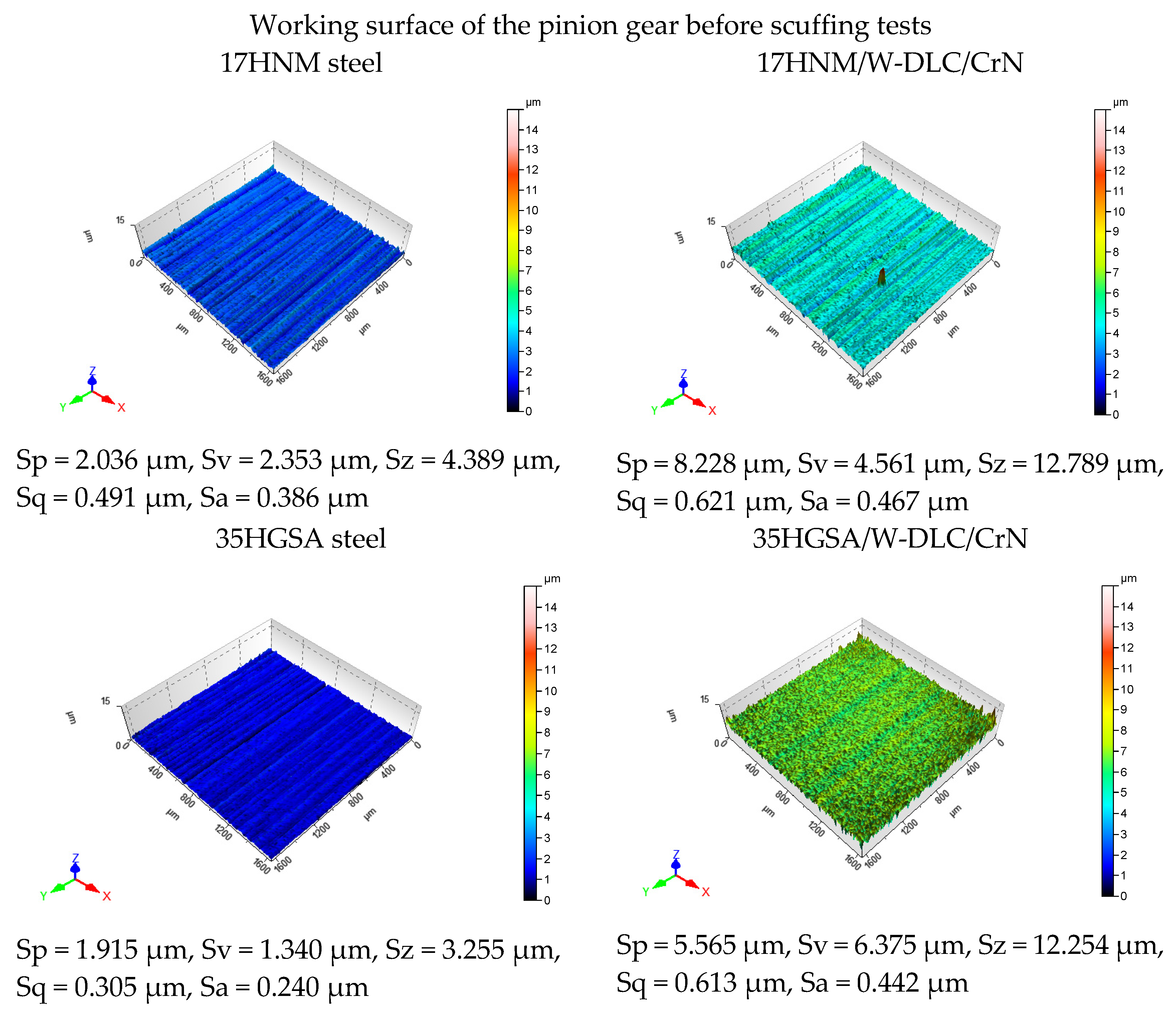
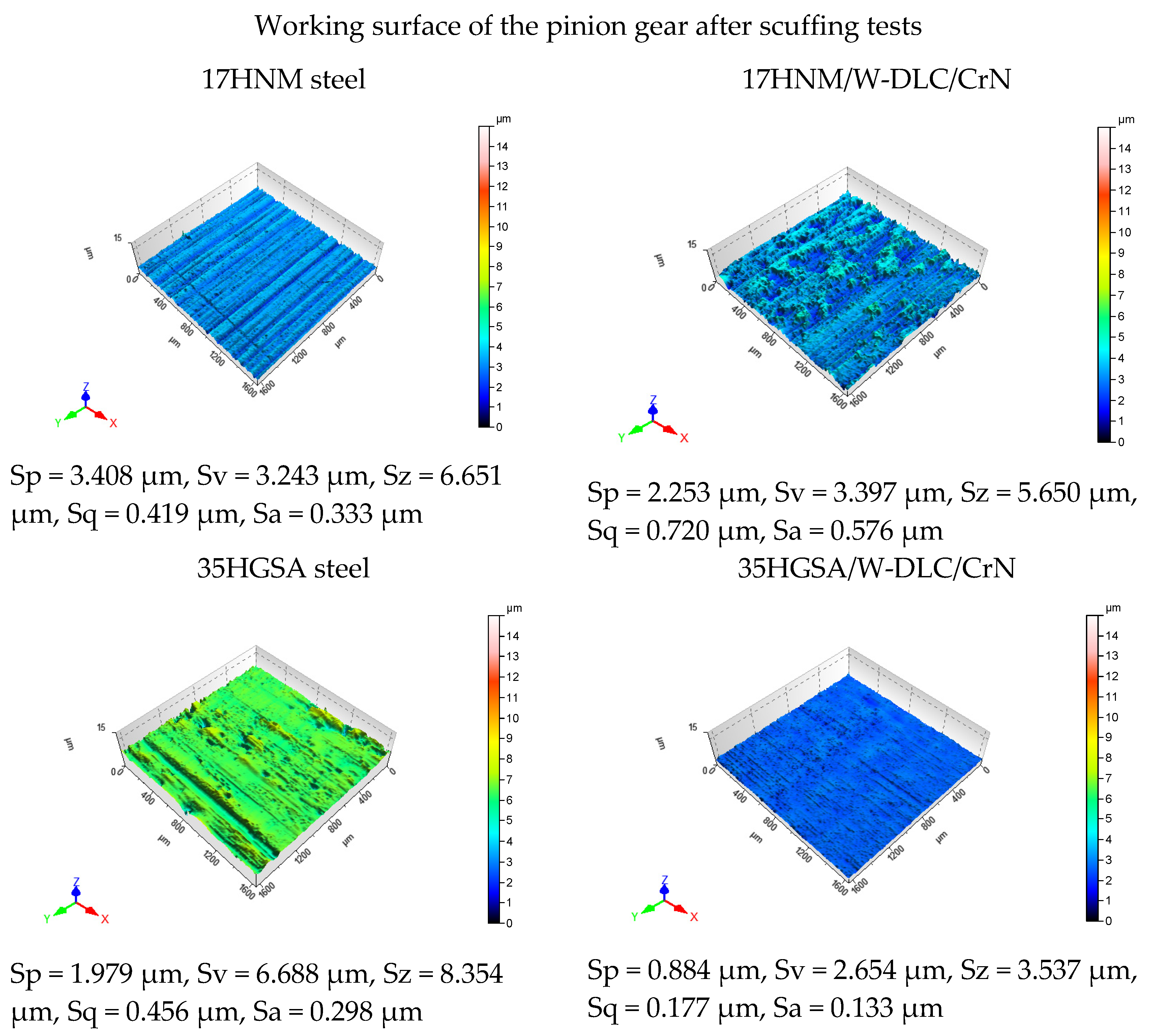
3. Results
4. Conclusions
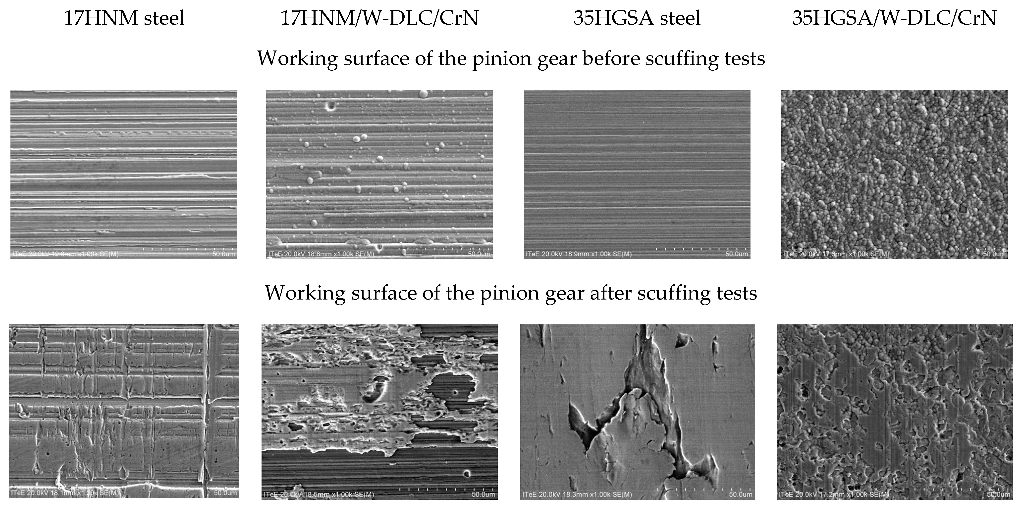
- Gears made of nanobainitized 35HGSA steel, after W-DLC/CrN coating deposition, achieved scuffing resistance at load level 10;
- The W-DLC/CrN coating deposited on the surface of gears made of the 35HGSA steel was not worn through;
- The working surface of the tooth made of the 35HGSA steel without the coating was subjected to scuffing at load level 10; additionally, dangerous forms of micropitting wear were observed;
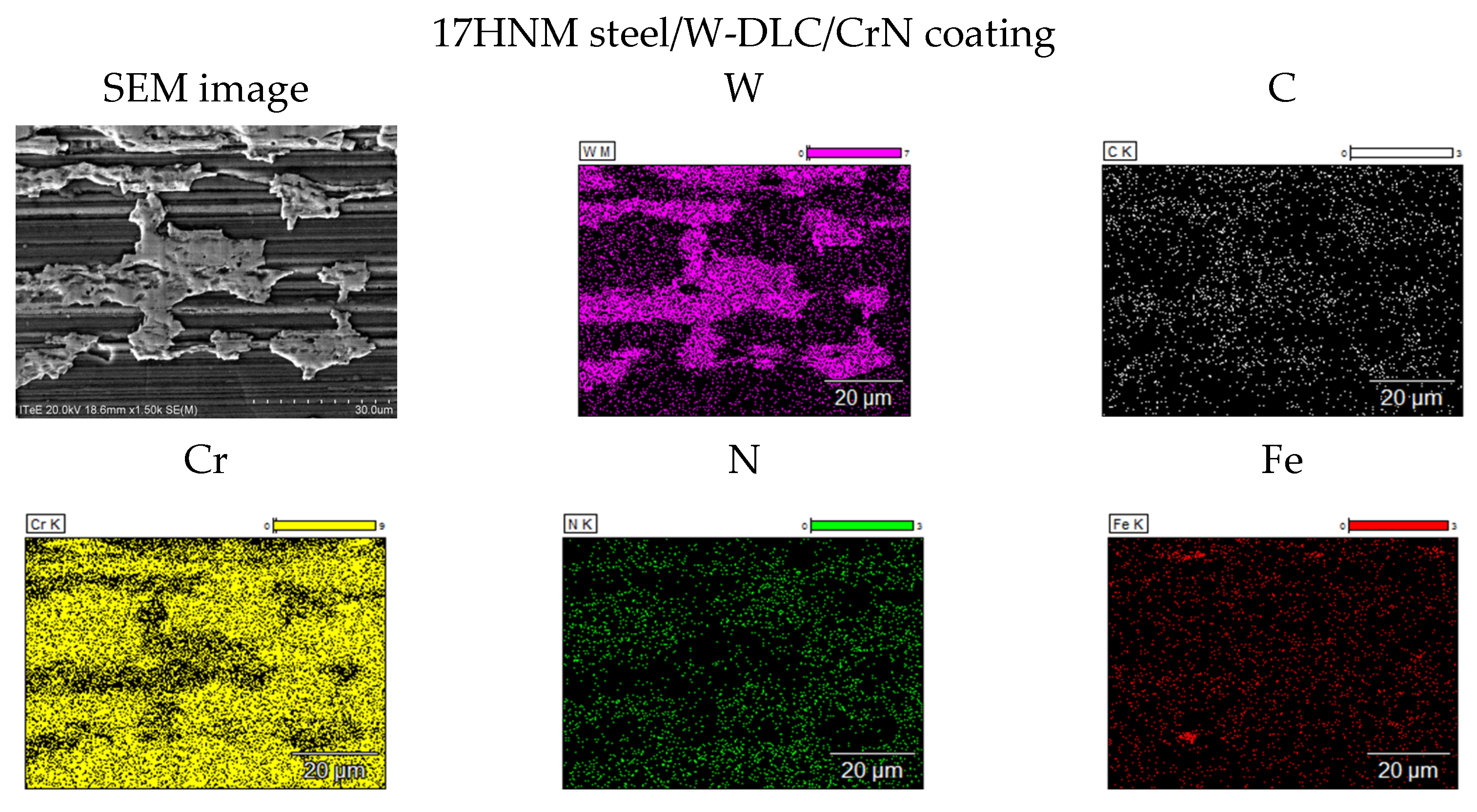
- The working surface of teeth made of the 17HNM steel, after the coating deposition process, was subjected to scuffing.
Author Contributions
Funding
Institutional Review Board Statement
Informed Consent Statement
Data Availability Statement
Conflicts of Interest
Abbreviations
| FLS | failure load stage |
| FZG | the Gear Research Centre (Forschungsstelle fur Zahnrader und Getriebebau, FZG) of the Technical University of Munich |
| PACVD | Plasma Assisted Chemical Vapor Deposition |
| GDOES | Glow Discharge Optical Emission Spectrometer |
| SEM | Scanning Electron Microscope |
| EDS | Energy Dispersive Spectrometer |
| WLI | White Light Interferometer Microscope |
| AFM | Atomic Force Microscope |
| Ra | profile roughness [µm] |
| Sa | surface roughness [µm] |
| Sp | maximum peak height [µm] |
| Sv | maximum indentation depth [µm] |
| Sz | maximum surface height [µm] |
| Sq | mean square deviation of the surface roughness [µm] |
| Ap | wear surface area [mm2] |
References
- Tuszyński, W.; Michalczewski, R.; Osuch-Słomka, E.; Snarski-Adamski, A.; Kalbarczyk, M.; Wieczorek, A.N.; Nędza, J. Abrasive wear, scuffing and rolling contact fatigue of DLC-coated 18CrNiMo7-6 steel lubricated by a pure and contaminated gear oil. Materials 2021, 14, 7086. [Google Scholar] [CrossRef] [PubMed]
- Wieczorek, A.N.; Wójcicki, M.; Drwięga, A.; Tuszyński, W.; Nuckowski, P.M.; Nędza, J. Abrasive wear of mining chain drums made of austempered ductile iron in different operating modes. Materials 2022, 15, 2709. [Google Scholar] [CrossRef] [PubMed]
- Martins, R.; Amaro, R.; Seabra, J. Influence of low friction coatings on the scuffing load capacity and efficiency of gears. Tribol. Int. 2008, 41, 234–243. [Google Scholar] [CrossRef]
- Vengudusamy, B.; Mufti, R.A.; Lamb, G.D.; Green, J.H.; Spikes, H.A. Friction properties of DLC/DLC contacts in base oil. Tribol. Int. 2011, 44, 922–932. [Google Scholar] [CrossRef]
- Höhn, B.R.; Michaelis, K.; Eberspächer, C.; Schlenk, L. A scuffing load capacity test with the FZG gear test rig for gear lubricants with high EP performance. Tribotest J. 1999, 5, 383–390. [Google Scholar] [CrossRef]
- Kalin, M.; Vižintin, J. The tribological performance of DLC-coated gears lubricated with biodegradable oil in various pinion/gear material combinations. Wear 2005, 259, 1270–1280. [Google Scholar] [CrossRef]
- Tuszynski, W.; Kalbarczyk, M.; Michalak, M.; Michalczewski, R.; Wieczorek, A. The effect of WC/C coating on the wear of bevel gears used in coal mines. Mater. Sci. 2015, 21, 358–363. [Google Scholar] [CrossRef]
- FVA Information Sheet No. 243 Status June 2000. Method to Assess the Scuffing Load Capacity of Lubricants with High EP Performance Using an FZG Gear Test Rig. 2000.
- Van De Velde, F.; Willen, P.; De Baets, P.; Van Geetruyen, C. Substitution of inexpensive bench tests for the FZG scuffing test—Part I: Calculations. Tribol. Trans. 1999, 42, 63–70. [Google Scholar] [CrossRef]
- Van De Velde, F.; Willen, P.; De Baets, P.; Van Geeteruyen, C. Substitution of inexpensive bench tests for the FZG scuffing test—Part II: Oil tests. Tribol. Trans. 1999, 42, 71–75. [Google Scholar] [CrossRef]
- Michalczewski, R.; Kalbarczyk, M.; Mańkowska-Snopczyńska, A.; Osuch-Słomka, E.; Piekoszewski, W.; Snarski-Adamski, A.; Szczerek, M.; Tuszyński, W.; Wulczyński, J.; Wieczorek, A. The effect of a gear oil on abrasion, scuffing, and pitting of the DLC-coated 18CrNiMo7-6 steel. Coatings 2019, 9, 2. [Google Scholar] [CrossRef]
- Tuszynski, W.; Michalczewski, R.; Piekoszewski, W.; Szczerek, M. Effect of ageing automotive gear oils on scuffing and pitting. Tribol. Int. 2008, 41, 875–888. [Google Scholar] [CrossRef]
- Michalczewski, R.; Piekoszewski, W.; Szczerek, M.; Tuszynski, W. The lubricant-coating interaction in rolling and sliding contacts. Tribol. Int. 2009, 42, 554–560. [Google Scholar] [CrossRef]
- Tuszynski, W.; Kalbarczyk, M.; Kiser, B.; Michalak, M.; Michalczewski, R.; Mydlarz, J.; Piekoszewski, W.; Szczerek, M.; Wulczynski, J. Testing of the resistance to scuffing of spiral bevel gears—Test rig, method and results of veri-fication testing. In Chaptering Collective Work: Friction, Lubrication and Wear; IntechOpen: London, UK, 2019. [Google Scholar] [CrossRef]
- Ronkainen, H.; Elomaa, O.; Varjus, S.; Kilpi, L.; Jaatinen, T.; Koskinen, J. The influence of carbon based coatings and surface finish on the tribological performance in high-load contacts. Tribol. Int. 2016, 96, 402–409. [Google Scholar] [CrossRef]
- Enthoven, J.; Spikes, H.A. Infrared and visual study of the mechanisms of scuffing. Tribol. Trans. 1996, 39, 441–447. [Google Scholar] [CrossRef]
- Moorthy, V.; Shaw, B. Effect of as-ground surface and the Balinit C and Nb-S coatings on contact fatigue damage in gears. Tribol. Int. 2012, 51, 61–70. [Google Scholar] [CrossRef]
- Wieczorek, A. Effect of construction changes in the teeth of a gear transmission on acoustic properties. Int. J. Occup. Saf. Ergon. 2012, 18, 499–507. [Google Scholar] [CrossRef] [PubMed]
- Onishchenko, V. Investigation of tooth wears from scuffing of heavy duty machine spur gears. Mech. Mach. Theory 2015, 83, 38–55. [Google Scholar] [CrossRef]
- Yoon, H.; Zhang, J.; Kelley, F. Scuffing Characteristics of SAE 50B38 Steel Under Lubricated Conditions. Tribol. Trans. 2011, 45, 246–252. [Google Scholar] [CrossRef]
- Chen, T.; Wei, P.; Zhu, C.; Zeng, P.; Li, D.; Parker, R.; Liu, H. Experimental Investigation of Gear Scuffing for Various Tooth Surface Treatments. Tribol. Trans. 2022, 66, 35–46. [Google Scholar] [CrossRef]
- Casto, J.; Sottomayor, A.; Seabra, J. Experimental and analytical scuffing criteria for FZG gears. Tribol. Interface Eng. Ser. 2004, 43, 651–661. [Google Scholar]
- Barth, Y.J.; Sagraloff, N.; Egger, G.; Tobie, T.; Stahl, K. Investigations on Ways to Improve the Scuffing and Wear Behavior of Oil-Free Water-Based Lubricants for Gear Applications. J. Tribol. 2024, 146, 054601. [Google Scholar] [CrossRef]
- Ríos-Diez, O.; Aristizábal-Sierra, R.; Serna-Giraldo, C.; Jimenez, J.A.; Garcia-Mateo, C. Development of nanobainitic microstructures in carbo-austempered cast steels: Heat treatment, microstructure and properties. Metals 2020, 10, 635. [Google Scholar] [CrossRef]
- Rementeria, R.; Morales-Rivas, L.; Kuntz, M.; Garcia-Mateo, C.; Kerscher, E.; Sourmail, T.; Caballero, F.G. On the role of microstructure in governing the fatigue behaviour of nanostructured bainitic steels. Mater. Sci. Eng. A 2015, 630, 71–77. [Google Scholar] [CrossRef]
- Solano-Alvarez, W.; Pickering, E.; Bhadeshia, H. Degradation of nanostructured bainitic steel under rolling contact fatigue. Mater. Sci. Eng. A 2014, 617, 156–164. [Google Scholar] [CrossRef]
- Łukaszewicz, G.; Szczygieł, M.; Węsierska-Hinca, M.; Chmielarz, K.; Wierzbicka, E.; Wasiak, K. Interrupted quenching and bainitising below Ms temperature of EN X37CrMoV5-1 hot-work tool steel: Bainitic transformation kinetics, microstructure and mechanical properties. Mater. Sci. Eng. A 2023, 869, 144740. [Google Scholar] [CrossRef]
- Morales-Rivas, L.; Azadi, A.; Kerscher, E. Fatigue behavior of nanostructured bainite: A morphological study of crack path. Procedia Struct. Integr. 2022, 39, 515–527. [Google Scholar] [CrossRef]
- ISO 14635-2:2023; Gears—FZG Test Producers. Part 2: FZG Step Load Test A10/16, 6R/120 for Relative Scuffing Load-Carrying Capacity of High EP Oils. ISO: Geneva, Switzerland, 2023.
- CEC L-84-02-ISSUE 1: 2002; FZG Scuffing Load Carrying Capacity Test for High EP Oils. Document Center Inc.: Belmont, CA, USA, 2002.


| Parameter | Substrate | |
|---|---|---|
| 17HNM Steel | 35HGSA Steel | |
| Thickness [um] | 4.8 | 3.8 |
| Adhesion [N] | 40 | 50 |
| Hardness [GPa] | 13.0 | 10.0 |
| Roughness Ra [um] | 0.39 | 0.34 |
| Roughness Sa [um] | 0.47 | 0.44 |
| Mode of Wear | Symbol | Appearance | 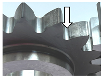 |
|---|---|---|---|
| Polishing | W |  | |
| Scratches | R |  | |
| Scoring | B |  | |
| Scuffing | Z |  |
| Load stage |  17HNM steel |  17HNM/W-DLC/CrN coating |  35HGSA steel |  35HGSA/W-DLC/CrN coating |
| 4 |  Ap ≈ 2.0 mm2 |  Ap ≈ 6.0 mm2 |  Ap ≈ 8.0 mm2 |  Ap ≈ 0.0 mm2 |
| 5 |  Ap ≈ 10.0 mm2 |  Ap ≈ 7.0 mm2 |  Ap ≈ 16.0 mm2 |  Ap ≈ 0.0 mm2 |
| 6 |  Ap ≈ 10.0 mm2 |  Ap ≈ 6.0 mm2 |  Ap ≈ 15.0 mm2 |  Ap ≈ 0.0 mm2 |
| 7 |  Ap ≈ 10.0 mm2 |  Ap ≈ 7.0 mm2 |  Ap ≈ 16.0 mm2 |  Ap ≈ 0.0 mm2 |
| 8 |  Ap ≈ 12.0 mm2 |  Ap ≈ 13.0 mm2 |  Ap ≈ 46.0 mm2 |  Ap ≈ 2.0 mm2 |
| 9 |  Ap ≈ 12.0 mm2 |  Ap ≈ 22.0 mm2 |  Ap ≈ 54.0 mm2 |  Ap ≈ 4.0 mm2 |
| 10 |  Ap ≈ 23.0 mm2 |  Ap ≈ 52.0 mm2 |  Ap ≈ 144.0 mm2 |  Ap ≈ 7.0 mm2 |
| Pinion Material | The Working Surface of the Pinion Gear after Scuffing Tests | |||
|---|---|---|---|---|
| FLS | Test Gear | Working Surface of The Pinion Tooth | Optical Microscope Image | |
| 17HNM steel | >10 |  |  |  |
| 17HNM/ W-DLC/CrN coating | >10 |  |  |  |
| 35HGSA steel | 10 |  |  |  |
| 35HGSA/ W-DLC/CrN coating | >10 |  |  |  |
Disclaimer/Publisher’s Note: The statements, opinions and data contained in all publications are solely those of the individual author(s) and contributor(s) and not of MDPI and/or the editor(s). MDPI and/or the editor(s) disclaim responsibility for any injury to people or property resulting from any ideas, methods, instructions or products referred to in the content. |
© 2024 by the authors. Licensee MDPI, Basel, Switzerland. This article is an open access article distributed under the terms and conditions of the Creative Commons Attribution (CC BY) license (https://creativecommons.org/licenses/by/4.0/).
Share and Cite
Osuch-Słomka, E.; Michalczewski, R.; Mańkowska-Snopczyńska, A.; Kalbarczyk, M.; Wieczorek, A.N.; Skołek, E. Wear Mechanisms of the Working Surface of Gears after Scuffing Tests. Materials 2024, 17, 3552. https://doi.org/10.3390/ma17143552
Osuch-Słomka E, Michalczewski R, Mańkowska-Snopczyńska A, Kalbarczyk M, Wieczorek AN, Skołek E. Wear Mechanisms of the Working Surface of Gears after Scuffing Tests. Materials. 2024; 17(14):3552. https://doi.org/10.3390/ma17143552
Chicago/Turabian StyleOsuch-Słomka, Edyta, Remigiusz Michalczewski, Anita Mańkowska-Snopczyńska, Marek Kalbarczyk, Andrzej N. Wieczorek, and Emilia Skołek. 2024. "Wear Mechanisms of the Working Surface of Gears after Scuffing Tests" Materials 17, no. 14: 3552. https://doi.org/10.3390/ma17143552