
Considerations for Tungsten Carbide as Tooling in RFSSW


Abstract
1. Introduction
2. Materials and Methods
2.1. Overview
2.2. Weld Details
2.3. Toolset Evaluations
2.4. Joint Evaluations
2.5. Other Testing
3. Results and Discussion
3.1. Preliminary Development
3.2. WC-Co Investigation
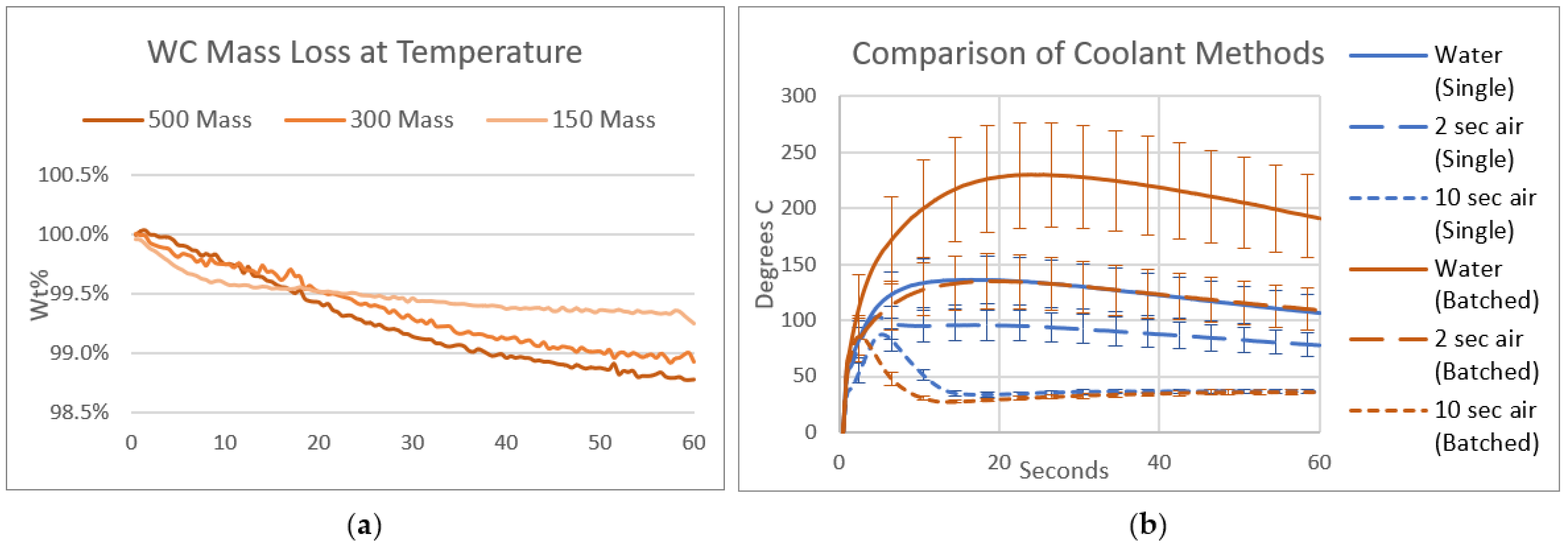
3.2.1. Thermal Considerations
3.2.2. Chemical Cleaning Considerations
3.3. Life Study
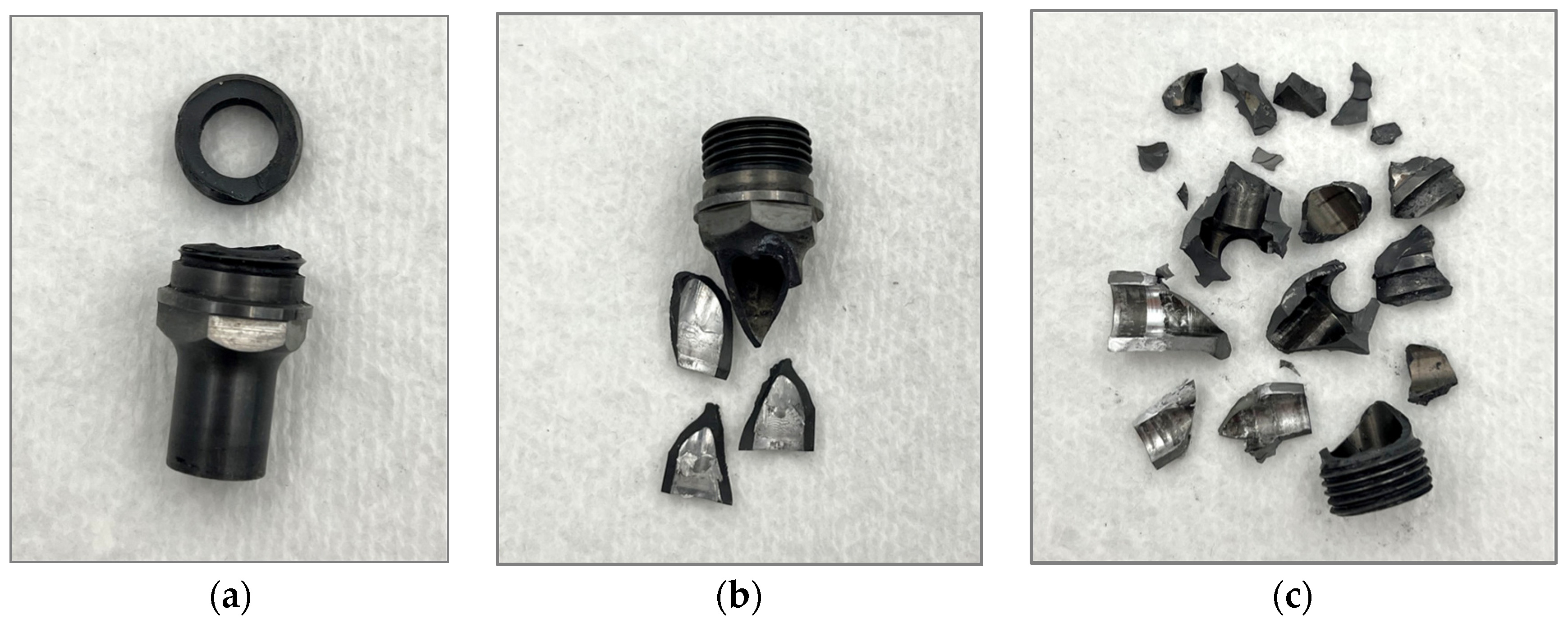
3.3.1. Seizures
3.3.2. Wear
3.3.3. Weld Quality
4. Conclusions
- For successful long-term use as RFSSW tooling, WC-Co must be cooled to temperatures beneath 150 °C.
- For successful long-term use as RFSSW tooling, WC-Co must not be cleaned with NaOH.
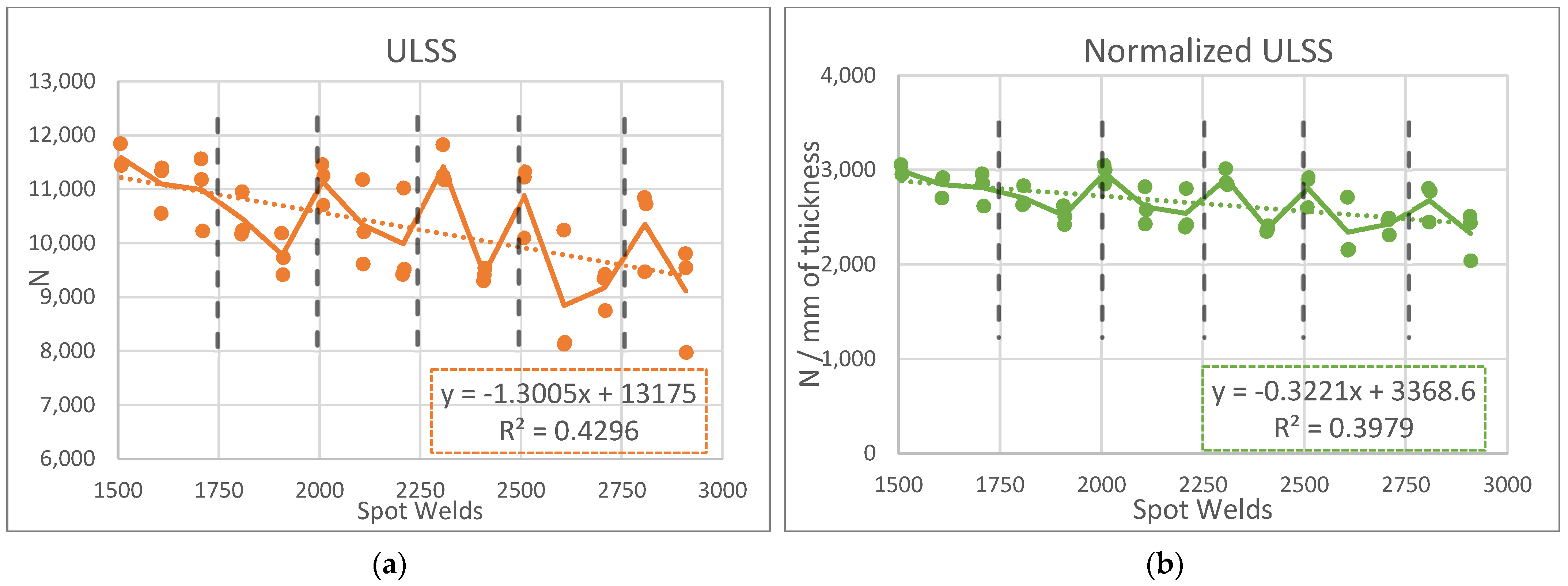
- Given control of the temperature and cleanliness, WC-Co tools can last for approximately 2998 welds without presenting significant wear on the shoulder or the probe.
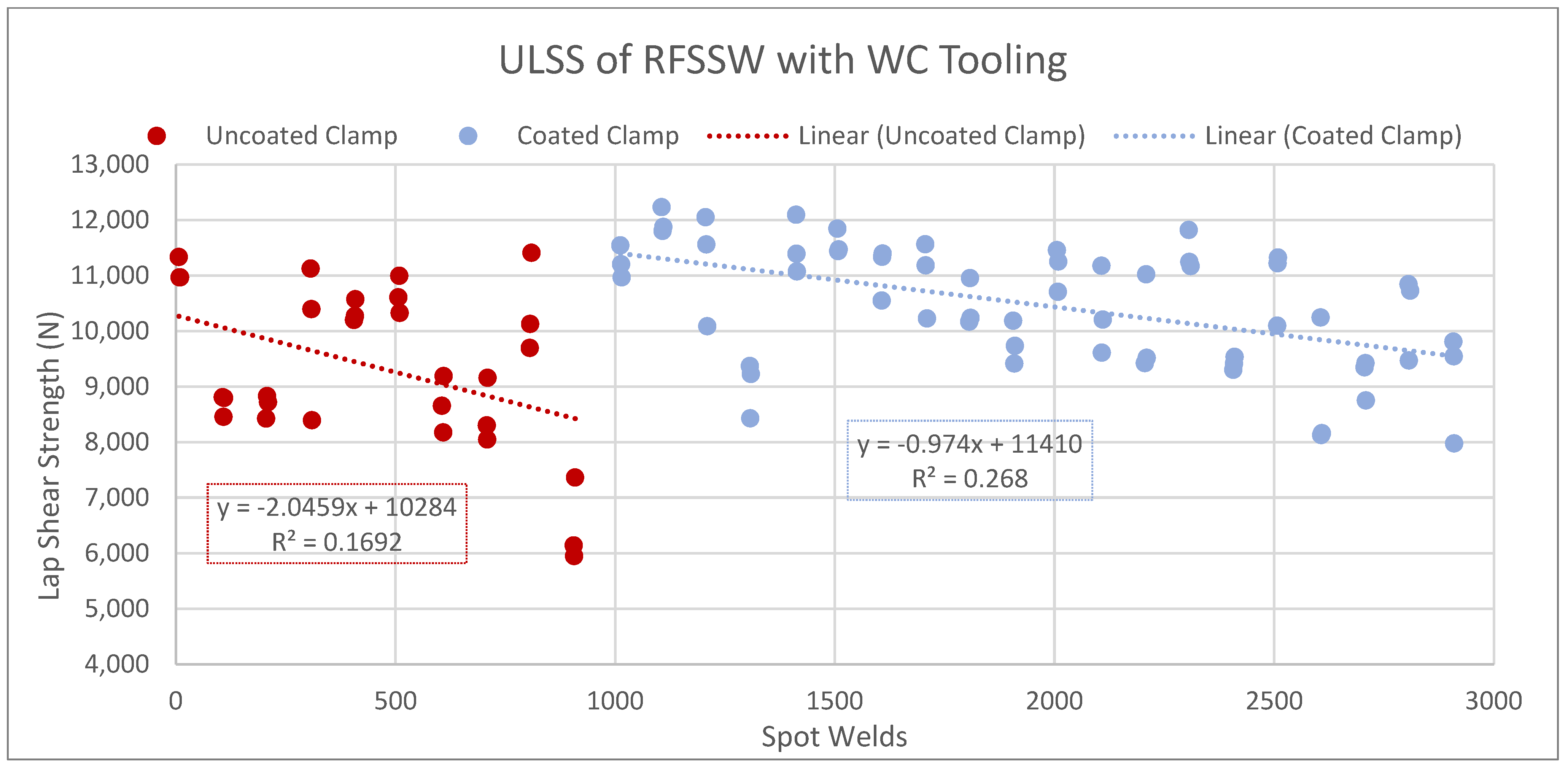
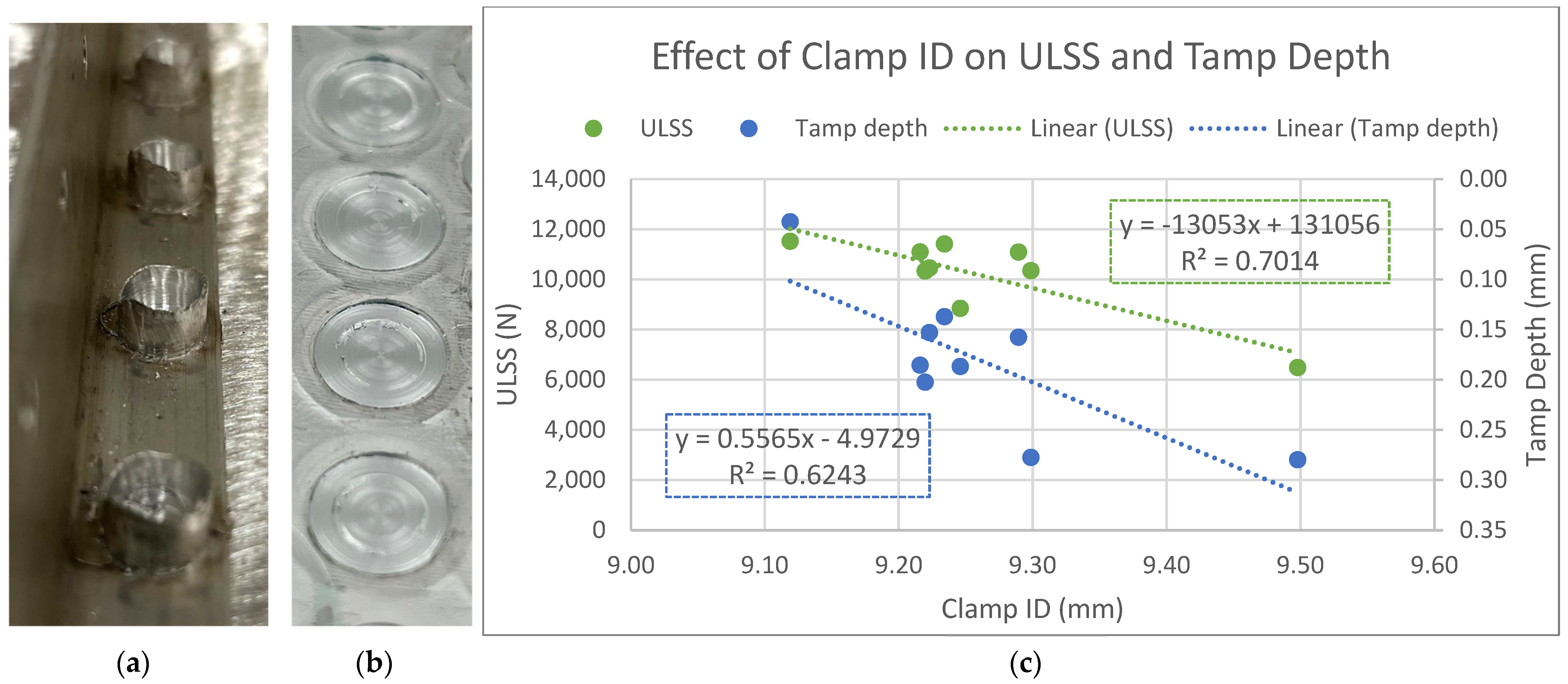
- In a configuration with a WC-Co probe/shoulder combination and an H13 clamp, the clamp will wear the fastest.
- Clamps coated with TiC exhibit wear approximately 38% slower than bare H13 clamps.
- Clamp wear contributes significantly to material loss during welding and a commensurate decrease in ULSS.
Author Contributions
Funding
Institutional Review Board Statement
Informed Consent Statement
Data Availability Statement
Acknowledgments
Conflicts of Interest
References
- Thomas, W.; Nicholas, E.; Needham, J.; Murch, M.; Templesmith, P.; Dawes, C. Friction stir welding. International Patent Application No. PCT/GB92/02203 and GB Patent Application No. 9125978.8. US Patent 1991, 460, 317. [Google Scholar]
- Avettand-Fènoël, M.-N.; Simar, A. A review about Friction Stir Welding of metal matrix composites. Mater. Charact. 2016, 120, 1–17. [Google Scholar] [CrossRef]
- Gangwar, K.; Ramulu, M. Friction stir welding of titanium alloys: A review. Mater. Des. 2018, 141, 230–255. [Google Scholar] [CrossRef]
- Huang, Y.; Meng, X.; Xie, Y.; Wan, L.; Lv, Z.; Cao, J.; Feng, J. Friction stir welding/processing of polymers and polymer matrix composites. Compos. Part A Appl. Sci. Manuf. 2018, 105, 235–257. [Google Scholar] [CrossRef]
- Lee, W.-B.; Jung, S.-B. The joint properties of copper by friction stir welding. Mater. Lett. 2004, 58, 1041–1046. [Google Scholar] [CrossRef]
- Lemos, G.V.B.; Hanke, S.; Dos Santos, J.F.; Bergmann, L.; Reguly, A.; Strohaecker, T.R. Progress in friction stir welding of Ni alloys. Sci. Technol. Weld. Join. 2017, 22, 643–657. [Google Scholar] [CrossRef]
- Liu, F.C.; Hovanski, Y.; Miles, M.P.; Sorensen, C.D.; Nelson, T.W. A review of friction stir welding of steels: Tool, material flow, microstructure, and properties. J. Mater. Sci. Technol. 2018, 34, 39–57. [Google Scholar] [CrossRef]
- Singh, K.; Singh, G.; Singh, H. Review on friction stir welding of magnesium alloys. J. Magnes. Alloys 2018, 6, 399–416. [Google Scholar] [CrossRef]
- Sivashanmugam, M.; Ravikumar, S.; Kumar, T.; Rao, V.S.; Muruganandam, D. A review on friction stir welding for aluminium alloys. In Proceedings of the Frontiers in Automobile and Mechanical Engineering, Tamilnadu, India, 7–8 September 2020. [Google Scholar]
- Rai, R.; De, A.; Bhadeshia, H.K.D.H.; DebRoy, T. Review: Friction stir welding tools. Sci. Technol. Weld. Join. 2011, 16, 325–342. [Google Scholar] [CrossRef]
- Zhang, Y.N.; Cao, X.; Larose, S.; Wanjara, P. Review of tools for friction stir welding and processing. Can. Metall. Q. 2012, 51, 250–261. [Google Scholar] [CrossRef]
- Christoph, S.; Jorge, d.S. Method and Device for Joining at Least Two Adjoining Work Pieces by Friction Welding. US 6722556B2, 20 April 2004. [Google Scholar]
- Feng, X.-S.; Li, S.-B.; Tang, L.-N.; Wang, H.-M. Refill Friction Stir Spot Welding of Similar and Dissimilar Alloys: A Review. Acta Metall. Sin. 2020, 33, 30–42. [Google Scholar] [CrossRef]
- Suryanarayanan, R.; Sridhar, V.G. Studies on the influence of process parameters in friction stir spot welded joints—A review. Mater. Today Proc. 2021, 37, 2695–2702. [Google Scholar] [CrossRef]
- Andres, J.; Wrońska, A.; Gałaczyński, T.; Luty, G.; Burek, R. Effect of process parameters on microstructure and mechanical properties of RFSSW lap joints of thin AL7075-T6 sheets. Arch. Metall. Mater. 2018, 63, 39–43. [Google Scholar] [CrossRef]
- Zhou, L.; Luo, L.Y.; Wang, R.; Zhang, J.B.; Huang, Y.X.; Song, X.G. Process Parameter Optimization in Refill Friction Spot Welding of 6061 Aluminum Alloys Using Response Surface Methodology. J. Mater. Eng. Perform. 2018, 27, 4050–4058. [Google Scholar] [CrossRef]
- Zou, Y.; Li, W.; Yang, X.; Su, Y.; Chu, Q.; Shen, Z. Microstructure and mechanical properties of refill friction stir spot welded joints: Effects of tool size and welding parameters. J. Mater. Res. Technol. 2022, 21, 5066–5080. [Google Scholar] [CrossRef]
- Zou, Y.; Li, W.; Shen, Z.; Su, Y.; Yang, X. Refill friction stir spot welding of aluminum alloys: State-of-the-art and Perspectives. Weld. World 2023, 67, 1853–1885. [Google Scholar] [CrossRef]
- Hovanski, Y.; Curtis, A.; Michaelis, S.; Blackhurst, P.; Larsen, B. Advances in Refill Spot Welding Productivity. In The Minerals, Metals & Materials Series; Springer International Publishing: Berlin/Heidelberg, Germany, 2021; pp. 189–197. [Google Scholar]
- Larsen, B.; Hovanski, Y. Reducing Cycle Times of Refill Friction Stir Spot Welding in Automotive Aluminum Alloys. In Proceedings of the WCX SAE World Congress Experience, Detroit, MI, USA, 21–23 April 2020. [Google Scholar]
- Montag, T.; Wulfsberg, J.-P.; Hameister, H.; Marschner, R. Influence of Tool Wear on Quality Criteria for Refill Friction Stir Spot Welding (RFSSW) Process. Procedia CIRP 2014, 24, 108–113. [Google Scholar] [CrossRef]
- De Carvalho, W.S.; Vioreanu, M.C.; Lutz, M.R.A.; Cipriano, G.P.; Amancio-Filho, S.T. The Influence of Tool Wear on the Mechanical Performance of AA6061-T6 Refill Friction Stir Spot Welds. Materials 2021, 14, 7252. [Google Scholar] [CrossRef] [PubMed]
- Larsen, B.; Hunt, J.; Hovanski, Y. Investigating steel tool life in the RFSSW process. J. Manuf. Process. 2020, 58, 637–645. [Google Scholar] [CrossRef]
- Nasiri, A.M.; Shen, Z.; Hou, J.S.C.; Gerlich, A.P. Failure analysis of tool used in refill friction stir spot welding of Al 2099 alloy. Eng. Fail. Anal. 2018, 84, 25–33. [Google Scholar] [CrossRef]
- De Castro, C.C.; Shen, J.; Plaine, A.H.; Suhuddin, U.F.H.; De Alcantara, N.G.; Dos Santos, J.F.; Klusemann, B. Tool wear mechanisms and effects on refill friction stir spot welding of AA2198-T8 sheets. J. Mater. Res. Technol. 2022, 20, 857–866. [Google Scholar] [CrossRef]
- Lauterbach, D.; Keil, D.; Harms, A.; Leupold, C.; Dilger, K. Tool wear behaviour and the influence of wear-resistant coatings during refill friction stir spot welding of aluminium alloys. Weld. World 2021, 65, 243–250. [Google Scholar] [CrossRef]
- Choi, D.H.; Lee, C.Y.; Ahn, B.W.; Choi, J.H.; Yeon, Y.M.; Song, K.; Park, H.S.; Kim, Y.J.; Yoo, C.D.; Jung, S.B. Frictional wear evaluation of WC–Co alloy tool in friction stir spot welding of low carbon steel plates. Int. J. Refract. Met. Hard Mater. 2009, 27, 931–936. [Google Scholar] [CrossRef]
- Tiwari, A.; Singh, P.; Pankaj, P.; Biswas, P.; Kore, S.D. FSW of low carbon steel using tungsten carbide (WC-10wt.%Co) based tool material. J. Mech. Sci. Technol. 2019, 33, 4931–4938. [Google Scholar] [CrossRef]
- Liu, H.J.; Feng, J.C.; Fujii, H.; Nogi, K. Wear characteristics of a WC–Co tool in friction stir welding of AC4A+30vol%SiCp composite. Int. J. Mach. Tools Manuf. 2005, 45, 1635–1639. [Google Scholar] [CrossRef]
- Prater, T.; Strauss, A.; Cook, G.; Gibson, B.; Cox, C. A Comparative Evaluation of the Wear Resistance of Various Tool Materials in Friction Stir Welding of Metal Matrix Composites. J. Mater. Eng. Perform. 2013, 22, 1807–1813. [Google Scholar] [CrossRef]
- Garrett, R.K.; Sanders, T.H. The formation of coarse intermetallics in rapidly solidified Al-Co alloys. Mater. Sci. Eng. 1983, 60, 269–274. [Google Scholar] [CrossRef]
- Belnap, R.; Smith, T.; Blackhurst, P.; Cobb, J.; Misak, H.; Bosker, J.; Hovanski, Y. Evaluating the Influence of Tool Material on the Performance of Refill Friction Stir Spot Welds in AA2029. J. Manuf. Mater. Process. 2024, 8, 88. [Google Scholar] [CrossRef]
- Chermant, J.L.; Osterstock, F. Fracture toughness and fracture of WC-Co composites. J. Mater. Sci. 1976, 11, 1939–1951. [Google Scholar] [CrossRef]
- Coating Selector Sheet. Available online: https://www.richterprecision.com/coating-data/technical-data/ (accessed on 15 January 2024).
- Institue, A.N.S. Speficication for Resistance Welding for Aerospace Applications; American Welding Society: Doral, FL, USA, 2018. [Google Scholar]
- Wang, B.; Wang, Z.; Yuan, J.; Yin, Z.; Huang, L.; Zheng, K. High temperature fracture mechanism of ultrafine WC-Co cemented carbides containing (Ti,W)C. Int. J. Refract. Met. Hard Mater. 2021, 95, 105428. [Google Scholar] [CrossRef]
- Belnap, R.; Blackhurst, P.; Hovanski, Y.; Curtis, A.; Cobb, J.; Misak, H. Production Evaluation of Refill Friction Stir Spot Welding. In Friction Stir Welding and Processing XII; Springer: Cham, Switzerland, 2023; pp. 139–148. [Google Scholar]
- Lee, J.; Kim, S.; Kim, B. A New Recycling Process for Tungsten Carbide Soft Scrap That Employs a Mechanochemical Reaction with Sodium Hydroxide. Metals 2017, 7, 230. [Google Scholar] [CrossRef]
- Quatrini, L.R. Process for Recovering Tungsten from Cemented Tungsten Carbide. US 4256708A, 17 March 1981. [Google Scholar]
- Lauterbach, D.; Keil, D.; Harms, A.; Schulze, M.; Dilger, K. Influence of Tool Wear on Weld Quality in Refill Friction Stir Spot Welding of Aluminium. In 2nd International Conference on Advanced Joining Processes (AJP 2021); Springer International Publishing: Berlin/Heidelberg, Germany, 2022; pp. 57–69. [Google Scholar]
- Tang, W.; Zhang, L.; Chen, Y.; Zhang, H.; Zhou, L. Corrosion and strength degradation behaviors of binderless WC material and WC–Co hardmetal in alkaline solution: A comparative investigation. Int. J. Refract. Met. Hard Mater. 2017, 68, 1–8. [Google Scholar] [CrossRef]
- Zhang, L.; Chen, Y.; Wan, Q.-l.; Liu, T.; Zhu, J.-f.; Tian, W. Electrochemical corrosion behaviors of straight WC–Co alloys: Exclusive variation in grain sizes and aggressive media. Int. J. Refract. Met. Hard Mater. 2016, 57, 70–77. [Google Scholar] [CrossRef]
- Upadhyay, P.; Reynolds, A.P. Effects of forge axis force and backing plate thermal diffusivity on FSW of AA6056. Mater. Sci. Eng. A 2012, 558, 394–402. [Google Scholar] [CrossRef]
- Upadhyay, P.; Reynolds, A.P. Thermal Management in Friction-Stir Welding of Precipitation-Hardened Aluminum Alloys. JOM 2015, 67, 1022–1031. [Google Scholar] [CrossRef]


| Cu | Mg | Ag | Mn | Zr | Si | Fe | Ti | Al |
|---|---|---|---|---|---|---|---|---|
| 3.2–4.0% | 0.8–1.1% | 0.3–0.5% | 0.2–0.4% | 0.08–0.15% | 0.12% max | 0.15% max | 0.15% max | Balance |
| RPM | Step Time | Shoulder Step | Probe Step |
|---|---|---|---|
| 3400 | 1.000 | −1.778 | 3.229 |
| 3400 | 0.500 | −1.000 | 1.000 |
| 2800 | 0.500 | 2.078 | −4.279 |
Disclaimer/Publisher’s Note: The statements, opinions and data contained in all publications are solely those of the individual author(s) and contributor(s) and not of MDPI and/or the editor(s). MDPI and/or the editor(s) disclaim responsibility for any injury to people or property resulting from any ideas, methods, instructions or products referred to in the content. |
© 2024 by the authors. Licensee MDPI, Basel, Switzerland. This article is an open access article distributed under the terms and conditions of the Creative Commons Attribution (CC BY) license (https://creativecommons.org/licenses/by/4.0/).
Share and Cite
Belnap, R.; Smith, T.; Wright, A.; Hovanski, Y. Considerations for Tungsten Carbide as Tooling in RFSSW. Materials 2024, 17, 3799. https://doi.org/10.3390/ma17153799
Belnap R, Smith T, Wright A, Hovanski Y. Considerations for Tungsten Carbide as Tooling in RFSSW. Materials. 2024; 17(15):3799. https://doi.org/10.3390/ma17153799
Chicago/Turabian StyleBelnap, Ruth, Taylor Smith, Arnold Wright, and Yuri Hovanski. 2024. "Considerations for Tungsten Carbide as Tooling in RFSSW" Materials 17, no. 15: 3799. https://doi.org/10.3390/ma17153799
APA StyleBelnap, R., Smith, T., Wright, A., & Hovanski, Y. (2024). Considerations for Tungsten Carbide as Tooling in RFSSW. Materials, 17(15), 3799. https://doi.org/10.3390/ma17153799