


A Review of Friction in Low-Stress Mechanics of Fibrous Flexible Materials

Abstract
:1. Introduction
2. Friction and Hysteresis Review Model
2.1. Coulomb Friction Laws
2.2. The Pre-Slip Model by Dahl
2.3. The Friction Model by Bliman and Sorine
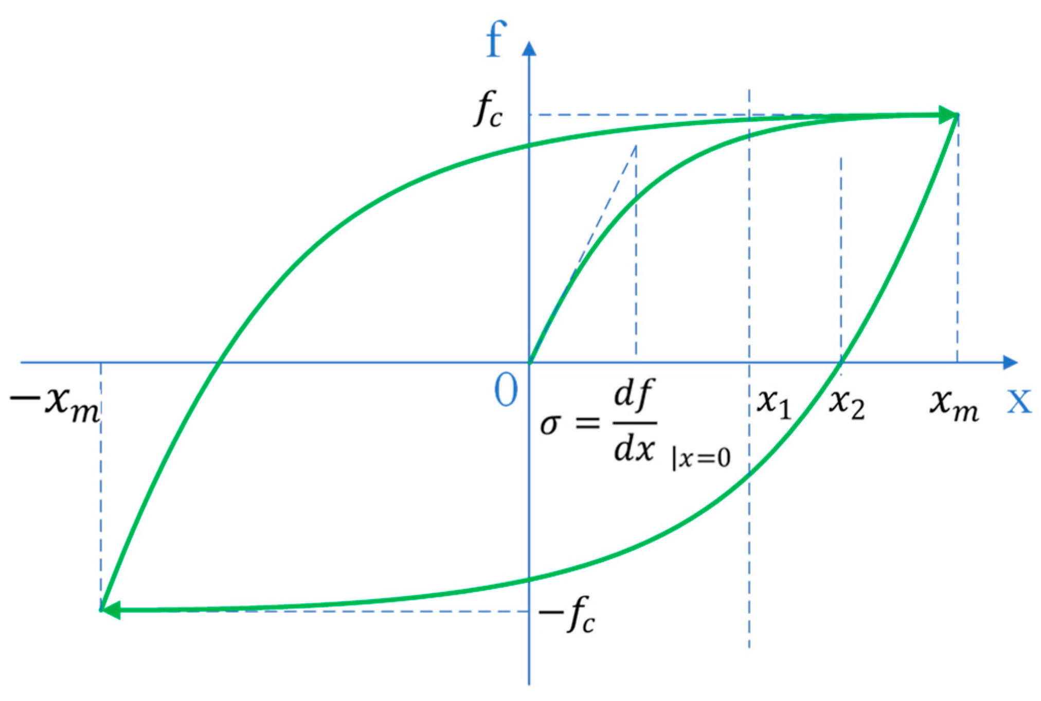
2.4. Hysteresis and Models
2.4.1. The Coexistence of Friction Hysteresis and Elastic Behaviour
2.4.2. Fabric Properties’ Equivalent Coulomb Friction as a Function of Deformation
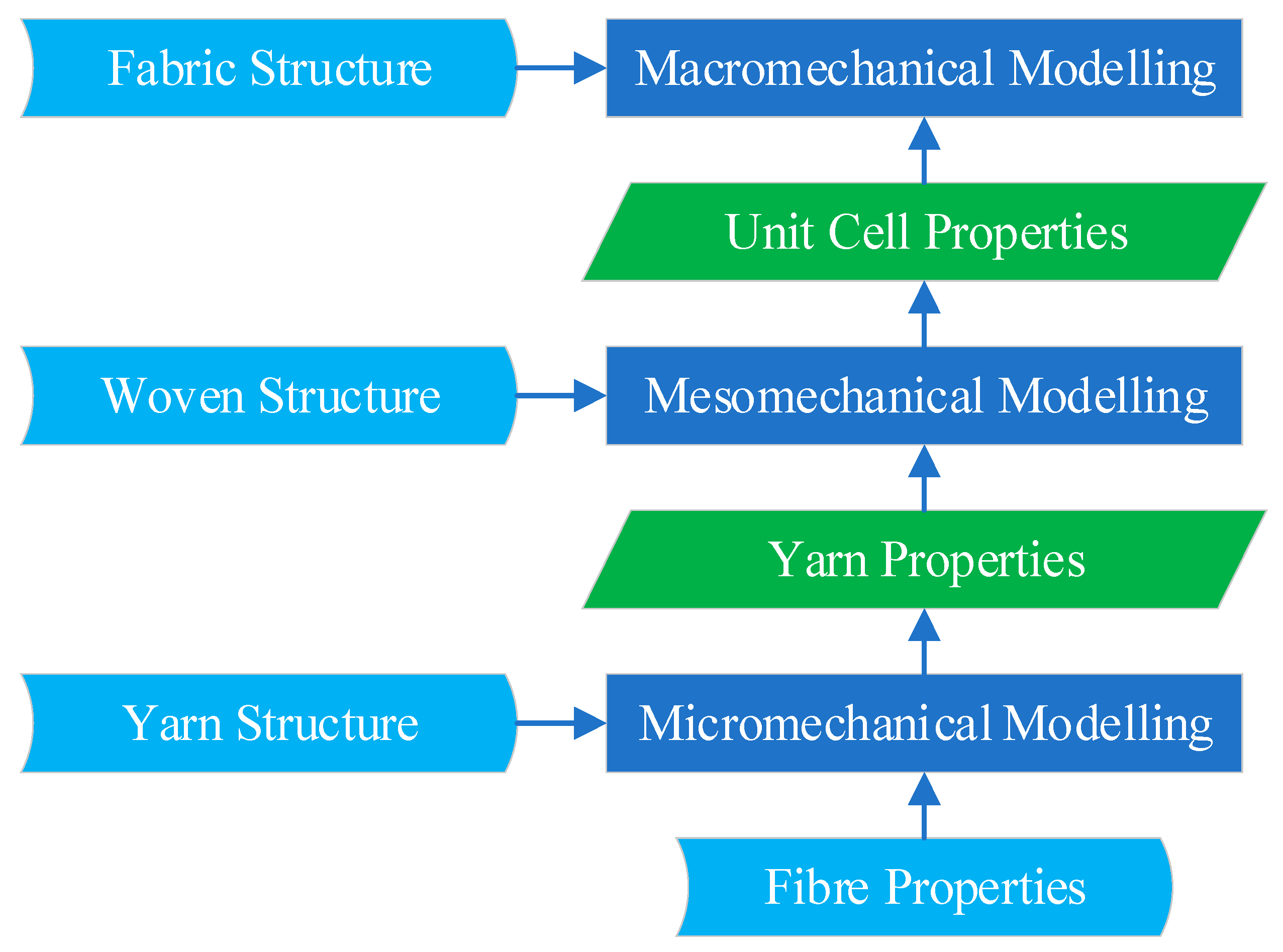
3. Fibre and Yarn Structure and Their Mechanical Relationship
3.1. Fibres
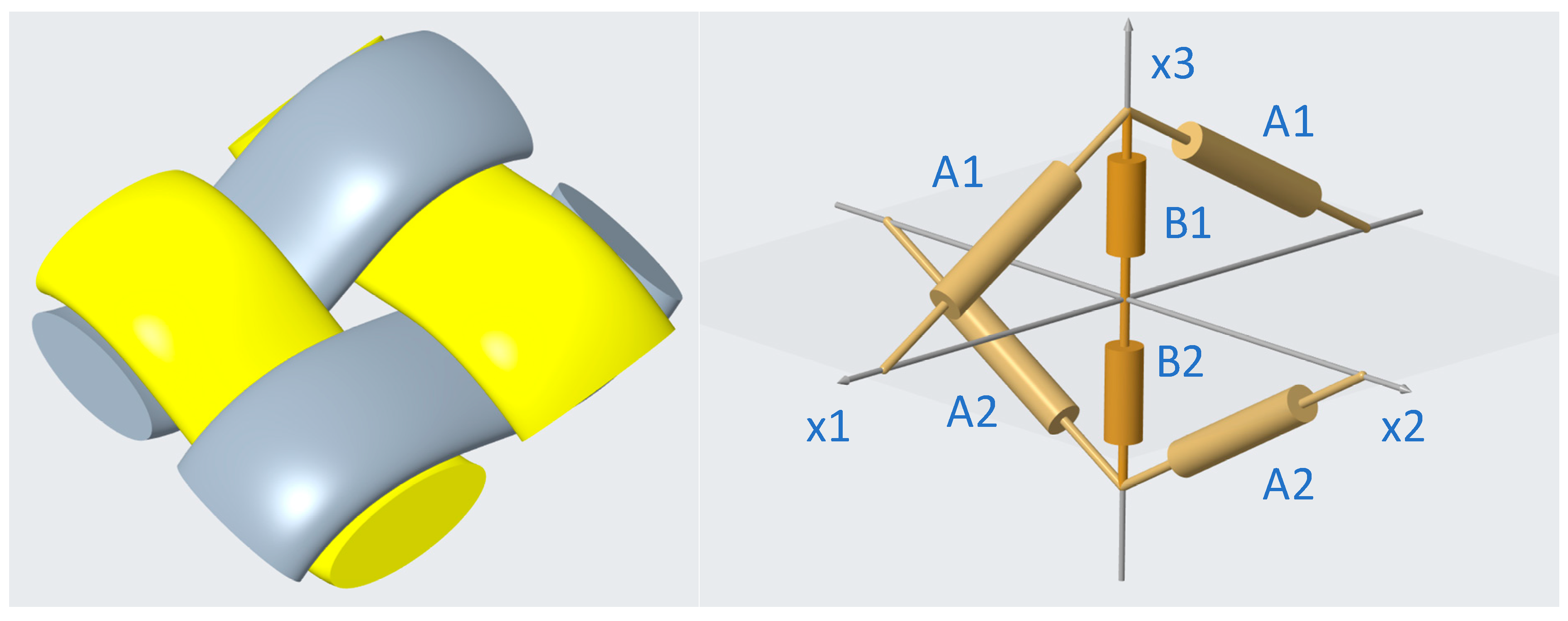
3.2. Yarn Structure
3.2.1. Yarn Stretching
3.2.2. Yarn Bending
3.3. Discussion Points on Yarn Friction
4. Fabric Deformation and Stress
4.1. In-Plane Deformation of Woven Fabrics
4.1.1. Tensile
4.1.2. Fabric Low-Stress Tensile Deformation and Crimp Exchange between Warp and Weft Yarns
4.1.3. Effect of Shear Deformation on Tensile Stress–Strain Relationship
4.1.4. Effect of Bending Deformation on Tensile Stress–Strain Relationship
4.1.5. Stress–Strain Relationship of Tensile Elastic Deformation
4.1.6. Inter-Fibre Friction during Tensile Deformation
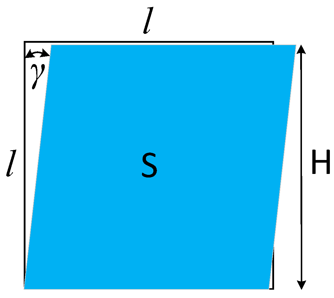
4.2. Shear
Shear Deformation
4.3. Bending
4.4. Other Studies on Fabric Friction
4.5. Discussion Points on Fabric Friction
5. Knitted Fabrics
6. Conclusions and Recommendation
Author Contributions
Funding
Institutional Review Board Statement
Informed Consent Statement
Data Availability Statement
Acknowledgments
Conflicts of Interest
References
- Yousef, M.I.; Stylios, G.K. Investigating the challenges of measuring combination mechanics in textile fabrics. Text. Res. J. 2018, 88, 2741–2754. [Google Scholar] [CrossRef]
- Timoshenko, S.; Goodier, J.N. Theory of Elasticity, 3rd ed.; McGraw-Hill: New York, NY, USA, 1970. [Google Scholar]
- Hu, J. Structure and Mechanics of Woven Fabrics; Elsevier Science: Cambridge, UK, 2004. [Google Scholar] [CrossRef]
- Popov, V.L. Contact Mechanics and Friction; Springer: Berlin/Heidelberg, Germany, 2017. [Google Scholar]
- Coulomb, C.A. Théorie des Machines Simples, en ayant égard au Frottement de leurs Parties, et a la Roideur des Cordages. piece qui a remporté le Prix double de l’Academie des Sciences pour l’année 1781. Available online: https://books.google.com.sg/books?id=BzAVAAAAQAAJ&printsec=frontcover#v=onepage&q&f=false (accessed on 21 June 2024).
- Popova, E.; Popov, V.L. The research works of Coulomb and Amontons and generalized laws of friction. Friction 2015, 3, 183–190. [Google Scholar] [CrossRef]
- Amontons, G. Mémoires de l’Académie RoyaleA; Académie Royale des Sciences: Paris, France, 1699; pp. 257–282. [Google Scholar]
- Dahl, P.R. A Solid Friction Model; TOR-0158 (3107-18-1); The Aerospace Corporation: El Segundo, CA, USA, 1968. [Google Scholar]
- Bliman, P. Mathematical study of the Dahl’s friction model. Eur. J. Mech. A-Solids 1992, 11, 835–848. [Google Scholar]
- Bliman, P.A.; Sorine, M. Friction Modeling by Hysteresis Operators: Application to Dahl, Sticktion, and Stribeck Effects; Models of Hysteresis, Longman Scientific and Technical: London, UK, 1993. [Google Scholar]
- Bliman, P.A.; Sorine, M. A System-Theoretic Approach of Systems with Hysteresis. Application to Friction Modelling and Compensation. In Proceedings of the 2nd European Control Conference, Gronigen, The Netherlands, 28 June–1 July 1993; European Union Control Association (EUCA): Groningen, The Netherlands, 1993; pp. 1844–1849. [Google Scholar]
- Bliman, P.A.; Sorine, M. Easy-to-use realistic dry frictionmodels for automatic control. In Proceedings of the 3rd European Control Conference, Rome, Italy, 5–8 September 1995; pp. 3788–3794. [Google Scholar]
- Ewing, J.A. Experimental research in magnetism. Philos. Trans. R. Soc. Lond. 1895, 176, 523–640. [Google Scholar]
- Mayergoyz, I.D. Mathematical models of hysteresis. IEEE Trans. Magn. 1986, 22, 603–608. [Google Scholar] [CrossRef]
- Yousef, M.I.; Stylios, G.K. Legacy of the Zeppelins: Defining fabrics as engineering materials. J. Text. Inst. 2015, 106, 480–489. [Google Scholar] [CrossRef]
- Luo, L.; Stylios, K.G. Algorithmic Information Theory for the Precise Engineering of Flexible Material Mechanics. Mach. Learn. Knowl. Extr. 2024, 6, 215–232. [Google Scholar] [CrossRef]
- Lawrence, C.A. Advances in Yarn Spinning Technology; Elsevier Science: Cambridge, UK, 2010. [Google Scholar] [CrossRef]
- Ognjanovic, R. 3—Yarn modelling. In Modelling and Predicting Textile Behaviour; Elsevier Ltd.: Amsterdam, The Netherlands, 2010; pp. 112–143. [Google Scholar] [CrossRef]
- Gupta, B.S. Textile Fiber Morphology, Structure and Properties in Relation to Friction. In Friction in Textile Materials; Woodhead Publishing: Sawston, UK, 2008; pp. 3–36. [Google Scholar] [CrossRef]
- Kutsenko, M.; Theyson, T.W. Finishes and treatments to control friction in textile fibers. In Friction in Textile Materials; Woodhead Publishing: Sawston, UK, 2008; pp. 386–418. [Google Scholar] [CrossRef]
- Hearle, J.W.S.; El-Behery, H.M.A.E.; Thakur, V.M. 15-The Mechanics of Twisted Yarns: Theoretical Developments. J. Text. Inst. Trans. 1961, 52, T197–T220. [Google Scholar] [CrossRef]
- Morton, W.E.; Yen, K.C. 37—Fibre Arrangement in Cotton Slivers and Laps. J. Text. Inst. Trans. 1952, 43, T463–T472. [Google Scholar] [CrossRef]
- Onions, W.J.; Toshniwal, R.L.; Townend, P.P. The Mixing of Fibres in Worsted Yarns. Part II-Fibre Migration. J. Text. Inst. Proc. 1960, 51, P62. [Google Scholar] [CrossRef]
- Hearle, J.W.S.; Merchant, V.B. 39-Interchange of Position Among the Components of a Seven-Ply Structure: Mechanism of Migration. J. Text. Inst. Trans. 1962, 53, T537–T552. [Google Scholar] [CrossRef]
- Hearle, J.W.S.; Bose, O.N. Migration of Fibers in Yarns: Parts I and II: A Geometrical Explanation of Migration. Text. Res. J. 1965, 35, 693–699. [Google Scholar] [CrossRef]
- El-Behery, H.M. Study of Theories of Fiber Migration—Need for More Fundamental Approach and Further Studies. Text. Res. J. 1968, 38, 321–331. [Google Scholar] [CrossRef]
- Sriprateep, K.; Bohez, E.L.J. A new computer geometric modelling approach of yarn structures for the conventional ring spinning process. J. Text. Inst. 2009, 100, 223–236. [Google Scholar] [CrossRef]
- Sriprateep, K.; Singto, S. New computer geometric modeling approach with filament assembly model for two-ply yarns structures. J. Text. Inst. 2019, 110, 1307–1317. [Google Scholar] [CrossRef]
- Aychilie, D.B.; Kyosev, Y.; Abtew, M.A. Automatic Modeller of Textile Yarns at Fibre Level. Materials 2022, 15, 8887. [Google Scholar] [CrossRef] [PubMed]
- Zhao, S.; Luan, F.; Bala, K. Fitting procedural yarn models for realistic cloth rendering. ACM Trans. Graph. 2016, 35, 1–11. [Google Scholar] [CrossRef]
- Gegauff, C. Strength and elasticity of cotton threads. Bull. Soc. Ind. Mulhouse 1907, 77, 153–176. [Google Scholar]
- Platt, M.M. Mechanics of Elastic Performance of Textile Materials: Part VI: Influence of Yarn Twist on Modulus of Elasticity. Text. Res. J. 1950, 20, 665–667. [Google Scholar] [CrossRef]
- Hearle, J.W.S.; Grosberg, P.; Backer, S. Structural Mechanics of Fibres, Yarns and Fabrics; Jonh Wiley & Sons Inc.: Hoboken, NJ, USA, 1969; ISBN 10:0471366692/13: 9780471366690. [Google Scholar]
- Huang, N.C.; Funk, G.E. Theory of Extension of Elastic Continuous Filament Yarns. Text. Res. J. 1975, 45, 14–24. [Google Scholar] [CrossRef]
- Van Langenhove, L. Simulating the Mechanical Properties of a Yarn Based on the Properties and Arrangement of its Fibers Parts I,2,3: The Finite Element Model. Text. Res. J. 1997, 67, 263–268. [Google Scholar] [CrossRef]
- Elmogahzy, Y. Yehia Elmogahzy, 1—Structure and mechanics of yarns. In Structure and Mechanics of Textile Fibre Assemblies, 2nd ed.; Schwartz, P., Ed.; The Textile Institute Book Series; Woodhead Publishing: Sawston, UK, 2019; pp. 1–25. ISBN 9780081026199. [Google Scholar] [CrossRef]
- Backer, S. The Mechanics of Bent Yarns. Text. Res. J. 1952, 22, 668–681. [Google Scholar] [CrossRef]
- Grosberg, P. The Mechanical Properties of Woven Fabrics Part II: The Bending of Woven Fabrics. Text. Res. J. 1966, 36, 205–211. [Google Scholar] [CrossRef]
- Park, J.W.; Oh, A.G. Bending Rigidity of Yarns. Text. Res. J. 2006, 76, 478–485. [Google Scholar] [CrossRef]
- Bral, A.; Daelemans, L.; Degroote, J. A Novel Technique to Simulate and Characterize Yarn Mechanical Behaviour Based on a Geometrical Fiber Model Extracted from Microcomputed Tomography Imaging. Text. Res. J. 2023, 93, 2042–2062. [Google Scholar] [CrossRef]
- Hearle, J.W.S.; Thwaites, J.J.; Amirbayat, J. Mechanics of Flexible Fiber Assemblies; NATO Advanced Study Institute Series; Sijthoff & Noordhoff: Alpen aan den Rijn, The Netherlands, 1980; p. 38. [Google Scholar]
- Kawabata, S.; Niwa, M.; Kawai, H. 3-The Finite-Deformation Theory of Plain-Weave Fabrics Part I: The Biaxial-Deformation Theory. J. Text. Inst. 1973, 64, 21–46. [Google Scholar] [CrossRef]
- Kawabata, S.; Niwa, M.; Kawai, H. 4-The Finite-Deformation Theory of Plain-Weave Fabrics. Part II: The Uniaxial-Deformation Theory. J. Text. Inst. 1973, 64, 47–61. [Google Scholar] [CrossRef]
- Kawabata, S.; Niwa, M.; Kawai, H. 5-The Finite-Deformation Theory of Plain-Weave Fabrics. Part III: The Shear-Deformation Theory. J. Text. Inst. 1973, 64, 62–85. [Google Scholar] [CrossRef]
- Kashani, M.H.; Rashidi, A.; Crawford, B.J.; Milani, A.S. Analysis of a two-way tension-shear coupling in woven fabrics under combined loading tests: Global to local transformation of non-orthogonal normalized forces and displacements. Compos. Part A Appl. Sci. Manuf. 2016, 88, 272–285. [Google Scholar] [CrossRef]
- Launay, J.; Hivet, G.; Duong, A.V.; Boisse, P. Experimental analysis of the influence of tensions on in plane shear behaviour of woven composite reinforcements. Compos. Sci. Technol. 2008, 68, 506–515. [Google Scholar] [CrossRef]
- Komeili, M.; Milani, A.S. On effect of shear-tension coupling in forming simulation of woven fabric reinforcements. Compos. Part B Eng. 2016, 99, 17–29. [Google Scholar] [CrossRef]
- Yousef, M.I.; Stylios, G.K. Novel Method for Testing Complex Combined Biaxial and Uniaxial Tensile and Shear Deformations in Woven Fabrics. Text. Res. J. 2024; submitted for publication. [Google Scholar]
- Wang, Y.; Zhang, W.; Ren, H.; Huang, Z.; Geng, F.; Li, Y.; Zhu, Z. An Analytical Model for the Tension-Shear Coupling of Woven Fabrics with Different Weave Patterns under Large Shear Deformation. Appl. Sci. 2020, 10, 1551. [Google Scholar] [CrossRef]
- Sun, H.; Pan, N. Shear deformation analysis for woven fabrics. Compos. Struct. 2005, 67, 317–322. [Google Scholar] [CrossRef]
- Jeddi, A.A.; Shams, S.; Nosraty, H.; Sarsharzadeh, A. Relations between Fabric Structure and Friction: Part I: Woven Fabrics. J. Text. Inst. 2003, 94, 223–234. [Google Scholar] [CrossRef]
- Hong, J.; Jayaraman, S. Friction in Textiles; The Textile Institute: Manchester, UK, 2003; Volume 34, ISBN 187037231X. [Google Scholar]
- Huang, C.; Cui, L.; Qiu, Y.; Zhang, C. Effects of inter-yarn friction on responses of woven fabrics with different weaves to a low-velocity impact. J. Eng. Fibers Fabr. 2023, 18, 15589250221149705. [Google Scholar] [CrossRef]
- Weierstrass, K. Über die Analytische Darstellbarkeit Sogenannter Willkürlicher Functionen einer Reellen Veränderlichen; Sitzungsberichte der Königlich Preußischen Akademie der Wissenschaften zu Berlin: Berlin, Germany, 1885; pp. 633–639 & 789–805. [Google Scholar]
Disclaimer/Publisher’s Note: The statements, opinions and data contained in all publications are solely those of the individual author(s) and contributor(s) and not of MDPI and/or the editor(s). MDPI and/or the editor(s) disclaim responsibility for any injury to people or property resulting from any ideas, methods, instructions or products referred to in the content. |
© 2024 by the authors. Licensee MDPI, Basel, Switzerland. This article is an open access article distributed under the terms and conditions of the Creative Commons Attribution (CC BY) license (https://creativecommons.org/licenses/by/4.0/).
Share and Cite
Luo, L.; Stylios, G. A Review of Friction in Low-Stress Mechanics of Fibrous Flexible Materials. Materials 2024, 17, 3828. https://doi.org/10.3390/ma17153828
Luo L, Stylios G. A Review of Friction in Low-Stress Mechanics of Fibrous Flexible Materials. Materials. 2024; 17(15):3828. https://doi.org/10.3390/ma17153828
Chicago/Turabian StyleLuo, Liang, and George Stylios. 2024. "A Review of Friction in Low-Stress Mechanics of Fibrous Flexible Materials" Materials 17, no. 15: 3828. https://doi.org/10.3390/ma17153828