
Performance and Microstructure of Grouting Materials Made from Shield Muck

Abstract
:1. Introduction
2. Experimental Scheme
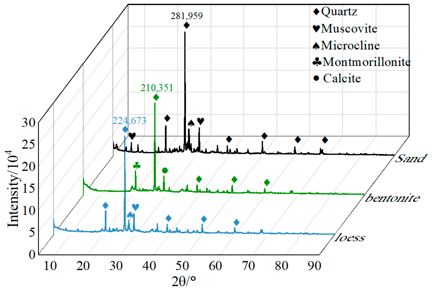
2.1. Materials
2.2. Experimental Design
2.3. Grout Preparation
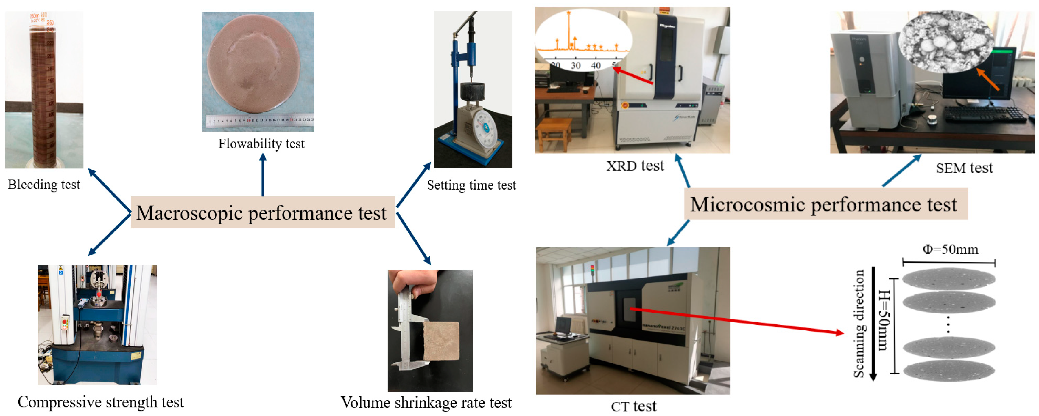
2.4. Test Methods
2.4.1. Fresh Property Tests
2.4.2. Mechanical Property Tests
2.4.3. Microstructure Property Tests
2.5. Performance Requirements
3. Results and Discussion
3.1. Fresh Properties
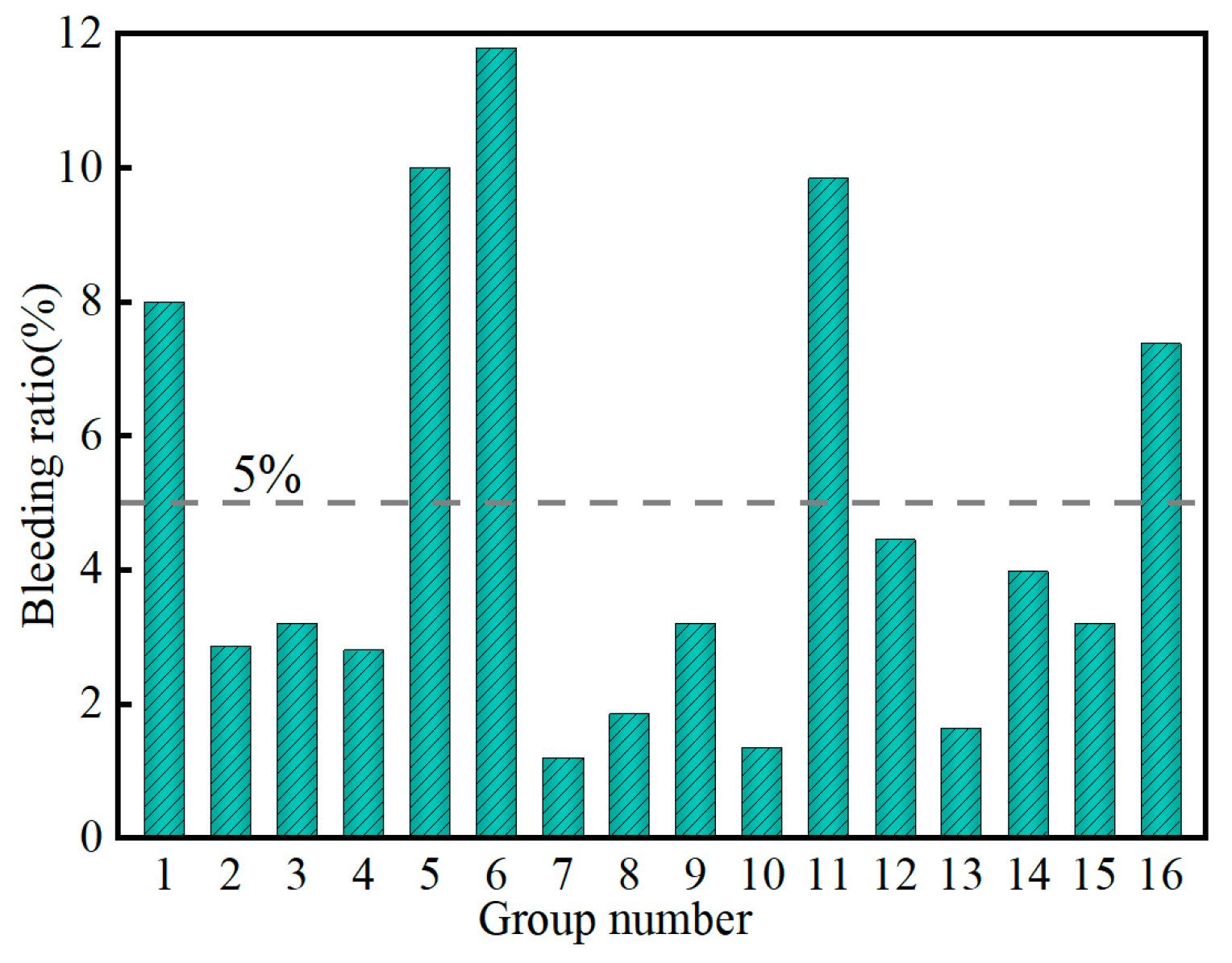
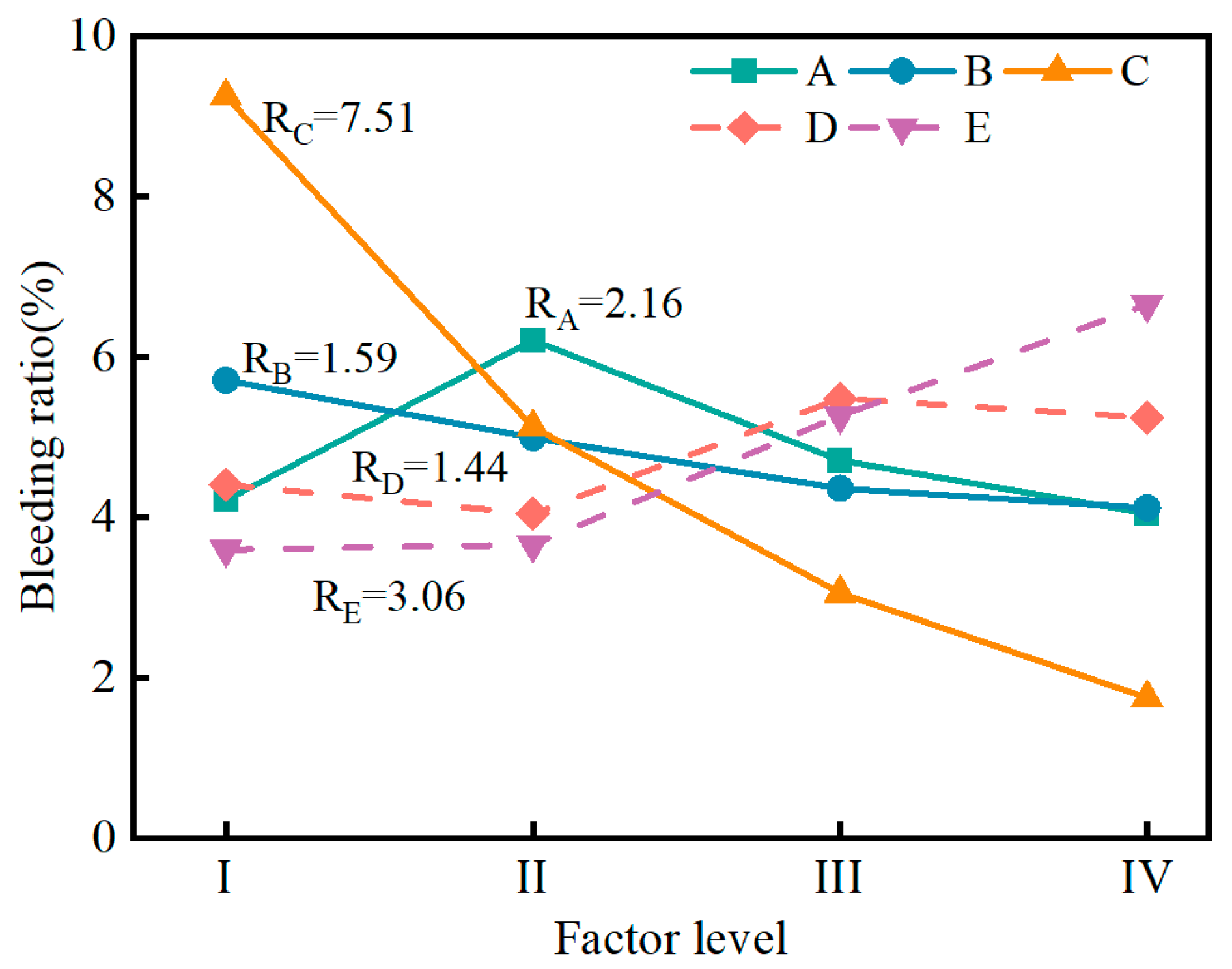
3.1.1. Influence of Factors on Bleeding Ratio
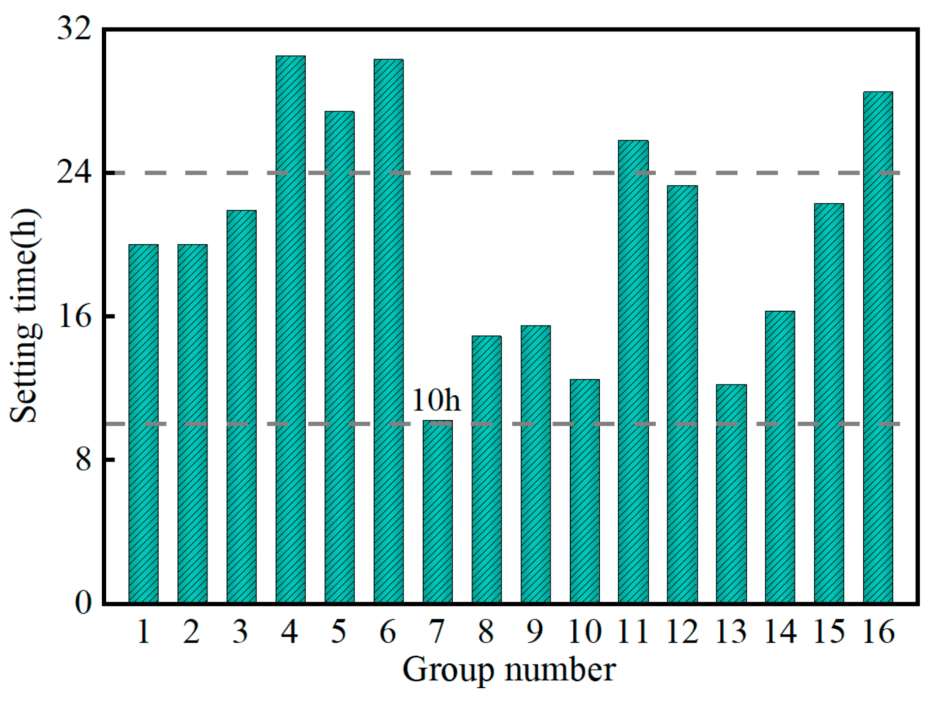
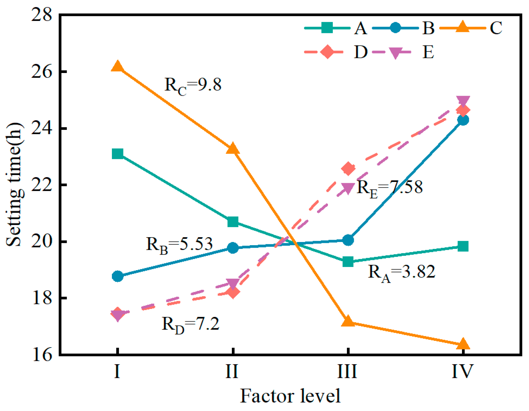
3.1.2. Influence of Factors on Setting Time
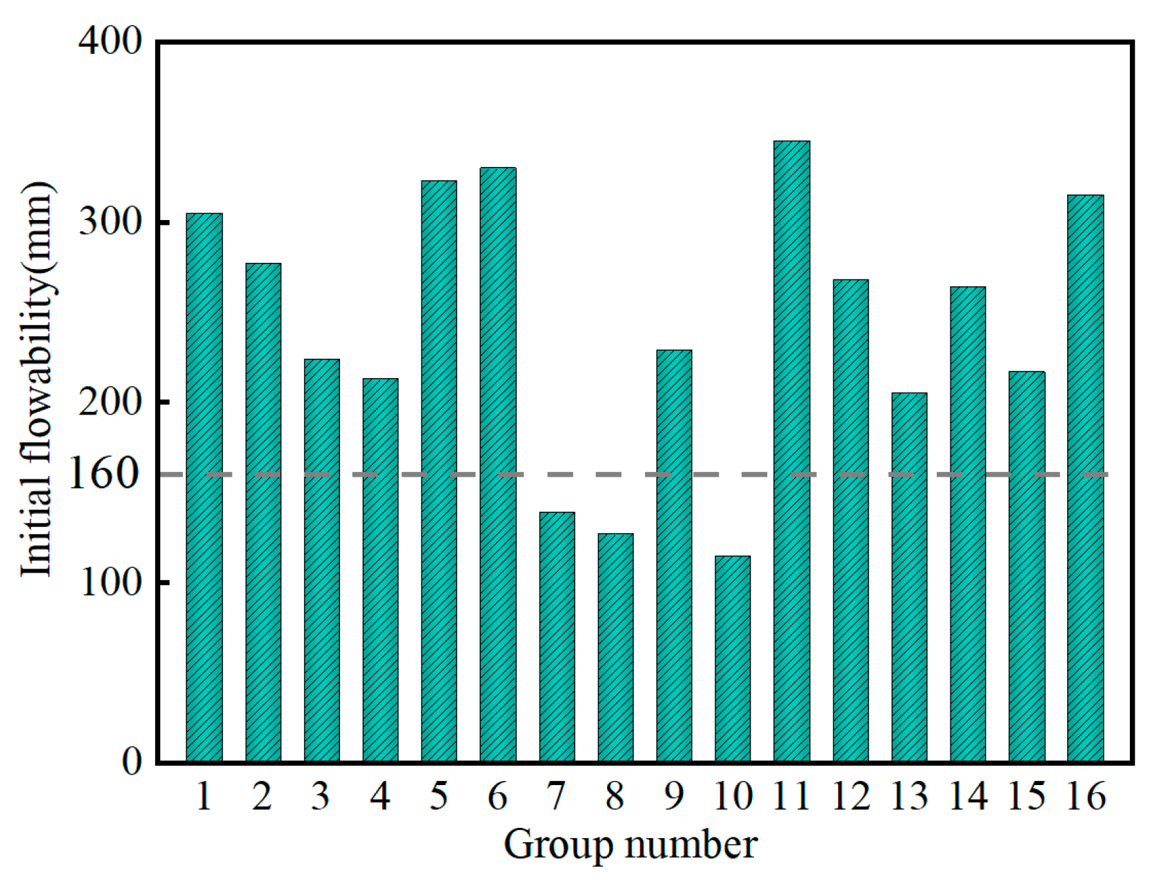
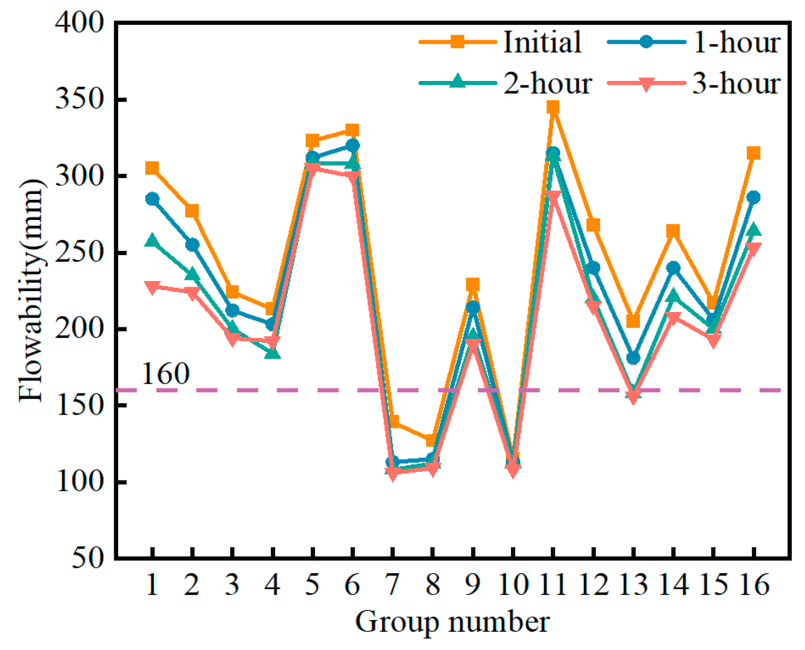
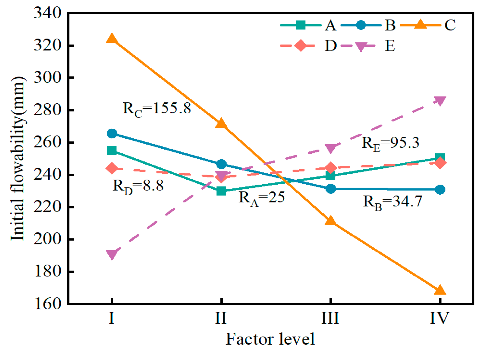
3.1.3. Influence of Factors on Flowability
3.2. Mechanical Properties
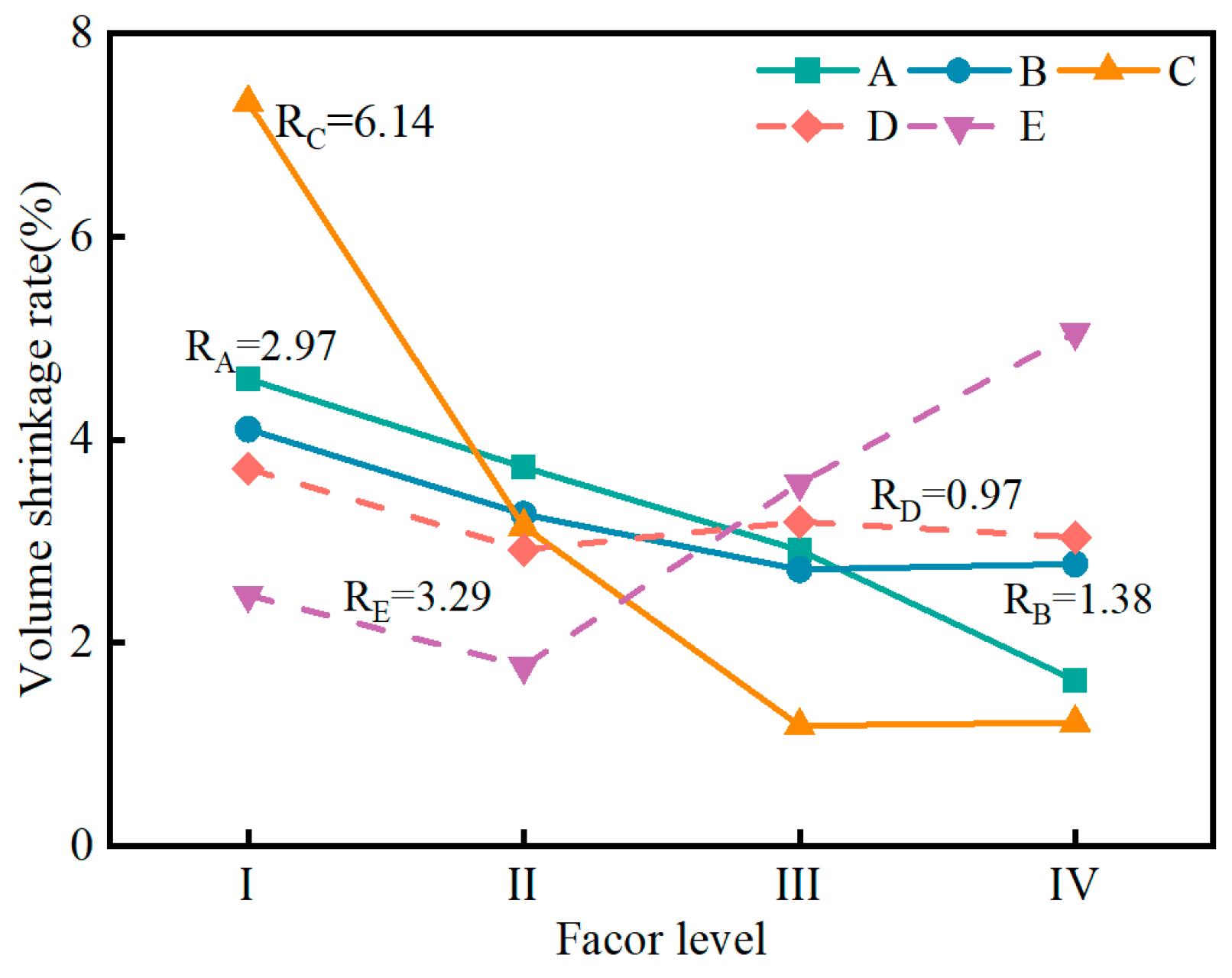
3.2.1. Influence of Factors on Volume Shrinkage Rate
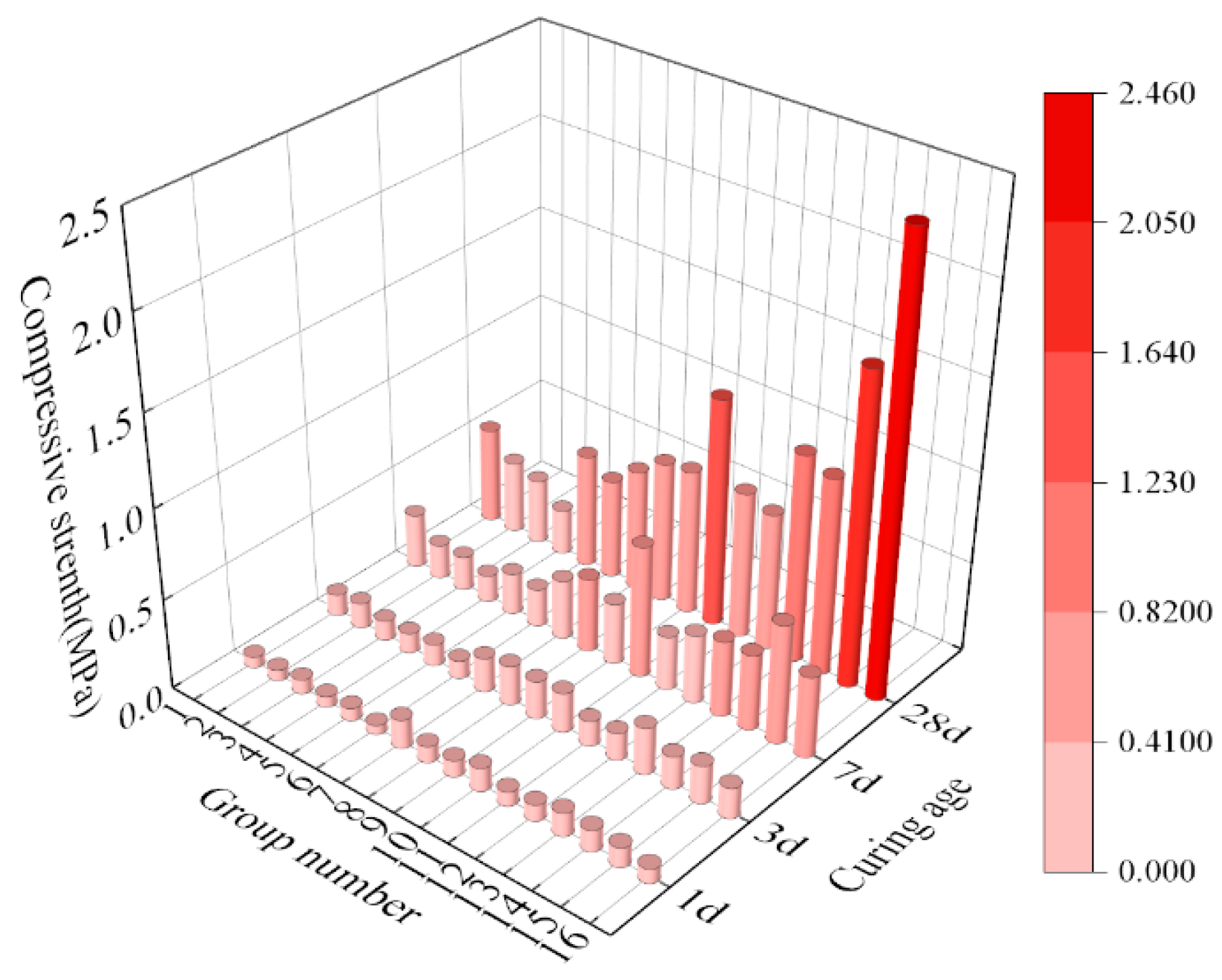
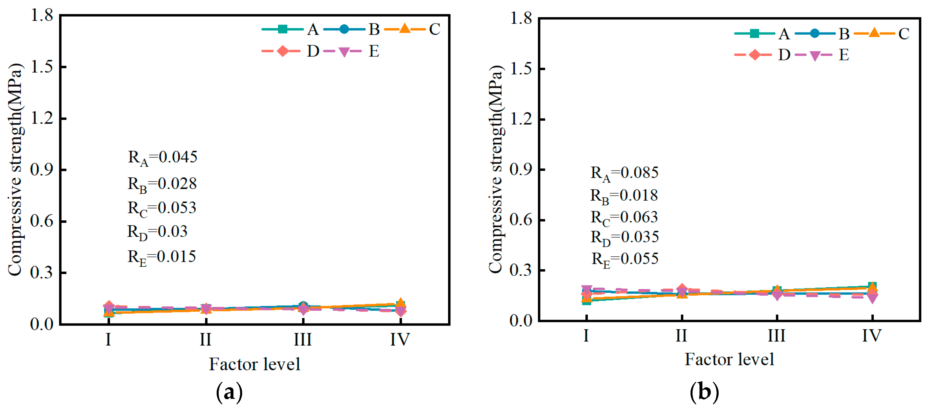
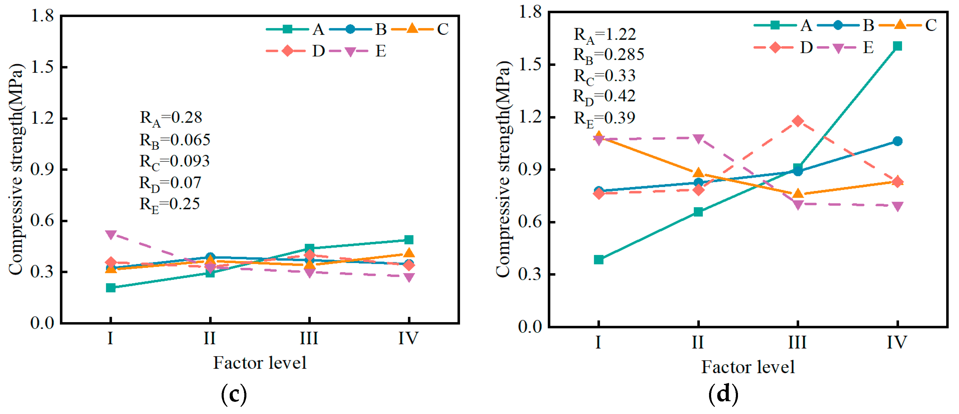
3.2.2. Influence of Factors on Compressive Strength
3.3. Microstructure Properties
3.3.1. XRD Analysis
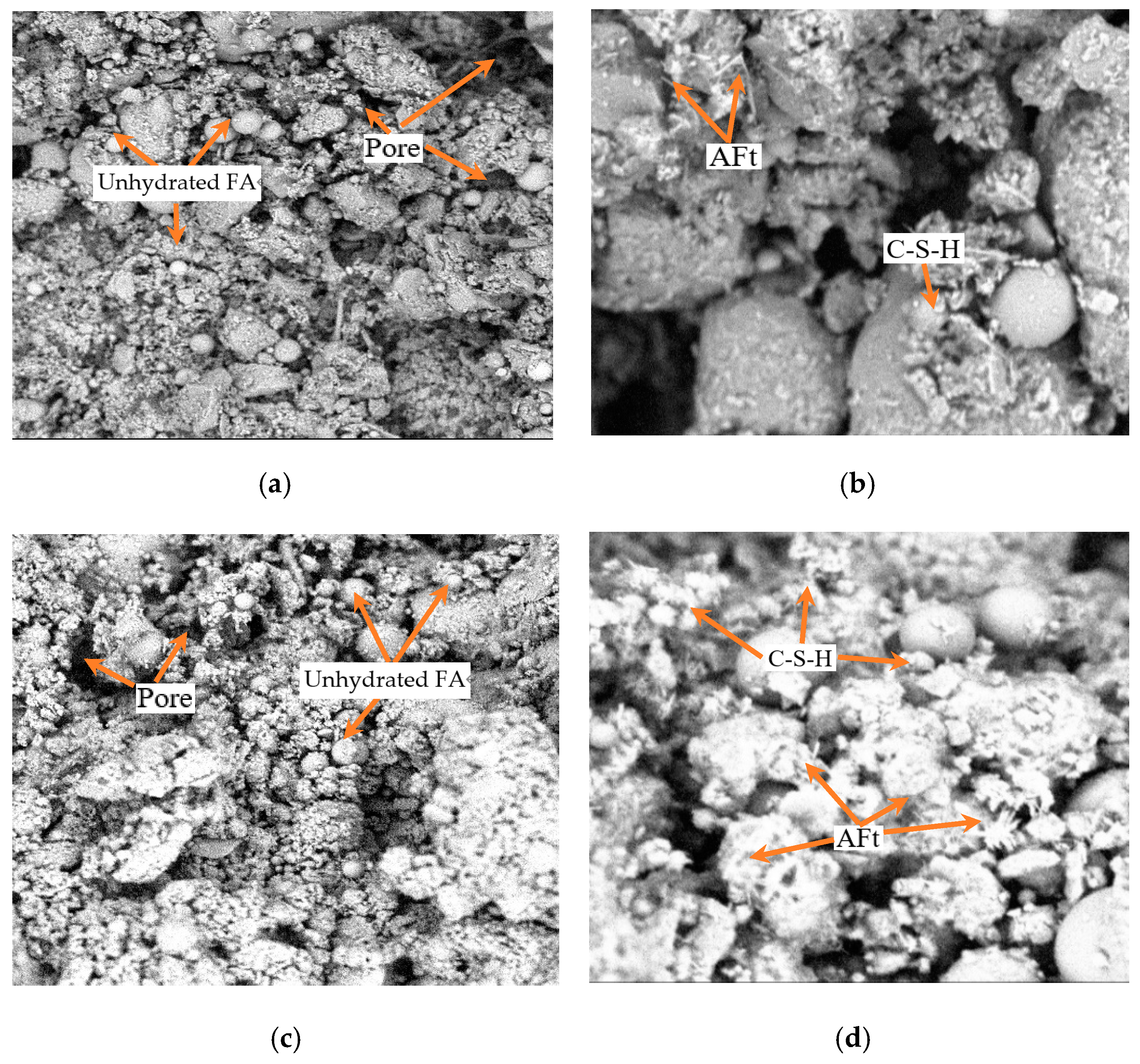
3.3.2. SEM Analysis
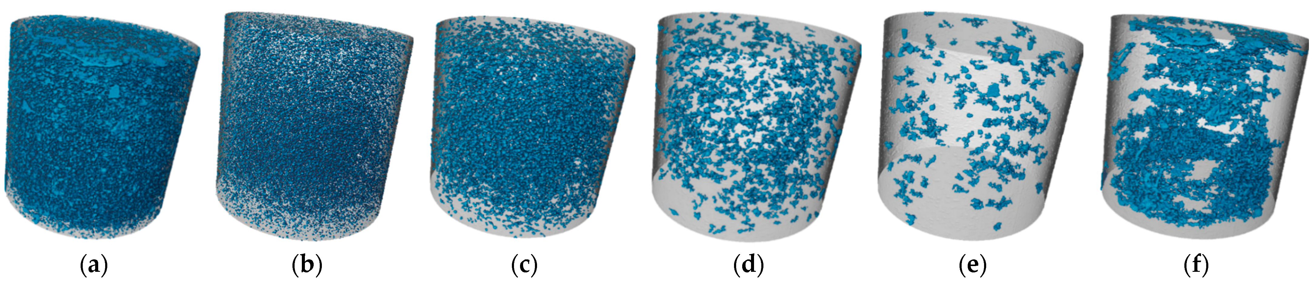
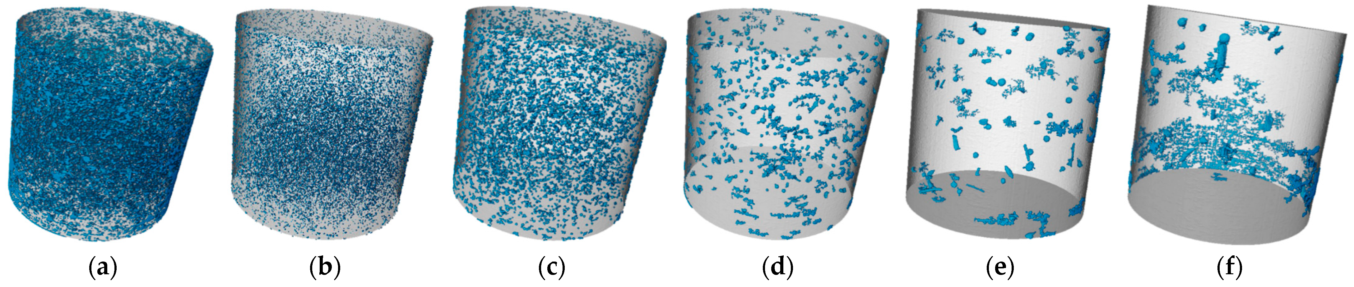
3.3.3. CT Analysis
4. Conclusions
- (1)
- The range analysis results indicate that the influence of muck content and water–solid ratio on the bleeding ratio, flowability, setting time, and volume shrinkage rate is greater than that of other factors. The influence of cement on the compressive strength is greater than other factors. A predictive model for the performance of the SMGM was established by using SPSS software (https://stats.oarc.ucla.edu/spss/, accessed on 14 August 2024), providing a reference for its practical application.
- (2)
- Through the combination of macro and micro methods, it was found that a dense internal structure is the main reason for the higher compressive strength. The analysis suggests that the filling effect of the gel substances and the particle aggregation effect reduce the pores of the SMGM, significantly improving their pore structure and compactness.
- (3)
- To meet the construction performance requirements and simplify the construction process, NO. 14 (12% for cement, 18% for fly ash, 50% for muck, 0.465 for water–solid ratio, 19.5% for river sand, 0.5% for bentonite) can be selected as the synchronous grouting for shield tunneling. Microstructural analysis results show that NO. 14 has a lower porosity and fewer pores compared to NO. 4.
Author Contributions
Funding
Institutional Review Board Statement
Informed Consent Statement
Data Availability Statement
Conflicts of Interest
Abbreviations
| SMGM | Shield muck grouting materials |
| XRD | X-ray diffraction |
| SEM | Scanning electron microscope |
| X-CT | X-ray computed tomography |
| FA | Fly ash |
| AFt | Ettringite |
| C-S-H | Hydrate calcium silicate |
References
- Shi, X.D.; Kou, L.; Liang, H.Y.; Wang, Y.B.; Li, W.X. Evaluating Carbon Emissions during Slurry Shield Tunneling for Sustainable Management Utilizing a Hybrid Life-Cycle Assessment Approach. Sustainability 2024, 16, 2702. [Google Scholar] [CrossRef]
- Lee, J.; Kim, G.; Kim, Y.; Mun, K.; Nam, J. Engineering properties and optimal conditions of cementless grouting materials. Materials 2019, 12, 3059. [Google Scholar] [CrossRef]
- Xie, Y.P.; Zhang, C.; Yang, J.S.; Fu, J.Y.; Xiao, C.; Zhan, Y.J. Research and Prospect on technology for resource recycling of shield tunnel spoil. Tunn. Constr. 2022, 42, 188–207. (In Chinese) [Google Scholar]
- Ni, Z.L.; Wang, S.Y.; Zheng, X.C.; Qi, C.H. Application of geopolymer in synchronous grouting for reusing of the shield muck in silty clay layer. Constr. Build. Mater. 2024, 419, 135345. [Google Scholar] [CrossRef]
- Wu, T.H.; Gao, Y.T.; Huang, C.F.; Jin, A.B.; Qu, X.C.; Ji, M.W.; Zhou, Y.; Li, J.W. In situ resource reutilization of earth pressure balance (EPB) shield muck for the generation of novel synchronous grouting materials. Constr. Build. Mater. 2024, 421, 135737. [Google Scholar] [CrossRef]
- Jia, J.M.; Ren, F.M.; Wei, X.; Gao, Y.H.; Qi, G.; Li, F.A.; Li, M.; Guo, C.A. Applying rail transit construction waste to make building materials: Using the theory of sustainable development. Environ. Sci. Pollut. Res. 2022, 29, 29663–29681. [Google Scholar] [CrossRef]
- Zhang, Y.J.; Wang, J.; Zhang, L.L.; Li, C.; Jiang, H.; Ba, X.Z.; Hou, D.S. Study on the preparation and properties of high-belite cementitious materials from shield slag and calcium carbide slag. Constr. Build. Mater. 2022, 355, 129082. [Google Scholar] [CrossRef]
- Voit, K.; Murr, T.R.; Cordes, O.Z.; Bergmeister, K. Tunnel spoil recycling for concrete production at the Brenner Base tunnel in Austria. Struct. Concr. 2020, 21, 2795–2809. [Google Scholar] [CrossRef]
- Riviera, P.P.; Bellopede, R.; Marini, P.; Bassani, M. Performance-based re-use of tunnel muck as granular material for subgrade and sub-base formation in road construction. Tunn. Undergr. Space Technol. 2014, 40, 160–173. [Google Scholar] [CrossRef]
- Shakya, S.; Inazumi, S.; Chao, K.C.; Wong, R.K. Innovative Design Method of Jet Grouting Systems for Sustainable Ground Improvements. Sustainability 2023, 15, 5602. [Google Scholar] [CrossRef]
- Wang, X.; Zhang, Y.D.; Zhao, W.; Wang, Z.P.; Wang, Z.G.; Wang, Y. Research on optimizing performance of new slurries for EPBS soil conditioning based on response surface method. Constr. Build. Mater. 2023, 375, 130818. [Google Scholar] [CrossRef]
- Vinai, R.; Oggeri, C.; Peila, D. Soil conditioning of sand for EPB applications: A laboratory research. Tunn. Undergr. Space Technol. 2008, 23, 308–317. [Google Scholar] [CrossRef]
- Zhou, S.H.; Li, X.; Ji, C.; Xiao, J.H. Back-fill grout experimental test for discharged soils reuse of the large-diameter size slurry shield tunnel. KSCE J. Civ. Eng. 2017, 21, 725–733. [Google Scholar] [CrossRef]
- Zhang, C.; Chen, K.; Yang, J.S.; Fu, J.Y.; Wang, S.Y.; Xie, Y.P. Reuse of Discharged Soil from Slurry Shield Tunnel Construction as Synchronous Grouting Material. J. Constr. Eng. Manag. 2022, 148, 04021193. [Google Scholar] [CrossRef]
- Wang, T. Experiment of shield synchronized grouting slurry using waste sand in sand layer. Appl. Mech. Mater. 2014, 638, 1600–1605. [Google Scholar] [CrossRef]
- Zhang, J.; Lu, S.D.; Feng, T.G.; Yi, B.B.; Liu, J.T. Research on reuse of silty fine sand in backfill grouting material and optimization of backfill grouting material proportions. Tunn. Undergr. Space Technol. 2022, 130, 104751. [Google Scholar] [CrossRef]
- Wang, R.; Xu, H.Q.; Liu, Y.; Jiang, P.; Zhou, A. Reusing Fine Silty Sand Excavated from Slurry Shield Tunnels as a Sustainable Raw Material for Synchronous Grouting. Coatings 2023, 13, 398. [Google Scholar] [CrossRef]
- Noorasyikin, M.N.; Zainab, M.; Derahman, A.; Dan, M.F.M.; Madun, A.; Yusof, Z.M.; Pakir, F. Mechanical properties of Bermuda grass roots towards sandy and clay soil for slope reinforcement. Phys. Chem. Earth Parts A/B/C 2022, 128, 103261. [Google Scholar] [CrossRef]
- Vu, Q.H.; Pereira, J.M.; Tang, A.M. Effect of clay content on the thermal conductivity of unfrozen and frozen sandy soils. Int. J. Heat Mass Transf. 2023, 206, 123923. [Google Scholar] [CrossRef]
- Duritsch, D. The Use of Non-Toxic Spent Foundry Sand into Controlled Low-Strength Materials in Ohio; The Institute of Advanced Manufacturing Sciences: Columbus, OH, USA, 1993. [Google Scholar]
- Sheen, Y.N.; Zhang, L.H.; Le, D.H. Engineering properties of soil-based controlled low-strength materials as slag partially substitutes to Portland cement. Constr. Build. Mater. 2013, 48, 822–829. [Google Scholar] [CrossRef]
- Wu, J.Y. Soil-based flowable fill for pipeline construction. In Pipelines 2005: Optimizing Pipeline Design, Operations, and Maintenance in Today’s Economy; American Society of Civil Engineers: Reston, VA, USA, 2005; pp. 925–938. [Google Scholar]
- GB/T 50123-2019; Standard for Geotechnical Testing Method. National Standards of People’s Republic of China: Beijing, China, 2009.
- Wan, Q.; Zhang, Y.M.; Zhang, R.B. Using mechanical activation of quartz to enhance the compressive strength of metakaolin based geopolymers. Cem. Concr. Compos. 2020, 111, 103635. [Google Scholar] [CrossRef]
- Shu, X.J.; Zhao, Y.; Li, H.H.; Zhao, C. Experimental study on the mix proportion of self-heating grouting materials in alpine regions. Constr. Build. Mater. 2023, 386, 131385. [Google Scholar] [CrossRef]
- Yang, X.L.; Dong, J.Y.; Yang, J.H.; Han, X.D. Similar Material Proportioning Tests and Mechanical Properties Based on Orthogonal Design. Materials 2023, 16, 6439. [Google Scholar] [CrossRef]
- Li, X.X.; Wang, M.; Zheng, D.; Fang, H.Y.; Wang, F.M.; Wan, J.C. Study on the failure mechanism between polyurethane grouting material and concrete considering the effect of moisture by digital image correlation. J. Build. Eng. 2023, 67, 105948. [Google Scholar] [CrossRef]
- Li, T.; Yue, Z.H.; Li, J.K.; Li, Q.H.; Li, Y.H.; Chen, G.B. Experimental study of improved cement silicate grouting material for broken surrounding rock. J. Build. Eng. 2023, 74, 106782. [Google Scholar] [CrossRef]
- T/CECS 563-2018; Technical Specification for Simultaneous Grouting Material in Shield Projects. China Association for Engineering Construction Standardization: Beijing, China, 2018.
- JGJ/T 70-2009; Standard for Test Method of Performance on Building Mortar. Ministry of Housing and Urban-Rural Development of the People’s Republic of China: Beijing, China, 2009.
- GB/T 50448-2008; Code for Application Technique of Cementitious Grout. National Standards of People’s Republic of China: Beijing, China, 2008.
- Xu, J.; Xiao, C.; Wu, H.N.; Kang, X. Reuse of Excavated clayey silt in cement–fly ash–bentonite hybrid back-fill grouting during shield tunneling. Sustainability 2020, 12, 1017. [Google Scholar] [CrossRef]
- Lu, Y.; Wan, T.; Huang, X.Y.; Lu, J.H.; Lin, S.; Nong, X.Z. Preliminary Mechanical Evaluation of Grouting Concrete as a Protective Layer for Tunnelling. Materials 2023, 16, 4957. [Google Scholar] [CrossRef]
- Inazumi, S.; Shakya, S.A. Comprehensive Review of Sustainable Assessment and Innovation in Jet Grouting Technologies. Sustainability 2024, 16, 4113. [Google Scholar] [CrossRef]
- Yin, S.H.; Zhou, Y.; Wang, L.M.; Pan, J.; Kou, Y.Y. Setting, bleeding, and hardening strength properties of coarse aggregate backfill slurry. Case Stud. Constr. Mater. 2022, 17, e01667. [Google Scholar] [CrossRef]
- Buranurak, S.; Pangza, K. Assessment of natural radioactivity levels and radiation hazards of Thai Portland cement brands using Gamma spectrometry technique. Mater. Today Proc. 2018, 5, 13979–13988. [Google Scholar] [CrossRef]
- Zheng, G.; Huang, J.Y.; Diao, Y.; Ma, A.Y.; Su, Y.M.; Chen, H. Formulation and performance of slow-setting cement-based grouting paste (SCGP) for capsule grouting technology using orthogonal test. Constr. Build. Mater. 2021, 302, 124204. [Google Scholar] [CrossRef]
- Kang, G.; Kim, Y.S.; Kang, J.G. Predictive strength model of cement-treated fine-grained soils using key parameters: Consideration of the total water/cement and soil/cement ratios. Case Stud. Constr. Mater. 2023, 18, e02069. [Google Scholar] [CrossRef]
- Zhang, X.H.; Song, Z.J.; Ding, Y.G. Predicting compressive strength of cement-based materials containing water-absorbent polymers considering the internal-curing region. Constr. Build. Mater. 2022, 360, 129594. [Google Scholar] [CrossRef]
- Zhang, T.; Sun, Z.P.; Yang, H.J.; Ji, Y.L.; Yan, Z.H. Enhancement of triisopropanolamine on the compressive strength development of cement paste incorporated with high content of wasted clay brick powder and its working mechanism. Constr. Build. Mater. 2021, 302, 124052. [Google Scholar] [CrossRef]
- Kaptan, K.; Cunha, S.; Aguiar, J. A Review: Construction and Demolition Waste as a Novel Source for CO2 Reduction in Portland Cement Production for Concrete. Sustainability 2024, 16, 585. [Google Scholar] [CrossRef]
- Dong, P.; Allahverdi, A.; Andrei, C.M.; Bassim, N.D. The effects of nano-silica on early-age hydration reactions of nano Portland cement. Cem. Concr. Compos. 2022, 133, 104698. [Google Scholar] [CrossRef]
- Llorens, J.; Julián, F.; Gifra, E.; Espinach, F.X.; Soler, J.; Chamorro, M.A. An Approach to Understanding the Hydration of Cement-Based Composites Reinforced with Untreated Natural Fibers. Sustainability 2023, 15, 9388. [Google Scholar] [CrossRef]
- Ran, B.; Metalssi, O.O.; Chong, T.F.; Dangla, P.; Li, K. Pore crystallization and expansion of cement pastes in sulfate solutions with and without chlorides. Cem. Concr. Res. 2023, 166, 107099. [Google Scholar] [CrossRef]
- Katarzna, K.-W.; Marta, K.-K.; Edyta, P. The properties of composites with recycled cement mortar used as a supplementary cementitious material. Materials 2019, 13, 64. [Google Scholar] [CrossRef] [PubMed]
- Wang, Y.J.; Zhou, H.W.; Fu, X. The Effect of Volcanic ash Pozzolan and Metakaolin on Electrochemical Corrosion Resistance of 2304 Duplex Stainless Steel Reinforcing in Concrete Subjected to Marine Environment. Int. J. Electrochem. Sci. 2022, 17, 220348. [Google Scholar]
- Cui, Y.; Tan, Z. Experimental study of high performance synchronous grouting materials prepared with clay. Materials 2021, 14, 1362. [Google Scholar] [CrossRef]
- Karim, M.R.; Hossain, M.M.; Khan, M.N.; Zain, M.F.; Jamil, M.; Lai, F.C. On the utilization of pozzolanic wastes as an alternative resource of cement. Materials 2014, 7, 7809–7827. [Google Scholar] [CrossRef]
- Wang, J.M.; Qin, Q.; Bai, Z.K. Characterizing the effects of opencast coal-mining and land reclamation on soil macropore distribution characteristics using 3D CT scanning. Catena 2018, 171, 212–221. [Google Scholar] [CrossRef]
- Song, W.L.; Zhu, Z.D.; Pu, S.Y.; Wan, Y.; Huo, W.W.; Song, S.G.; Zhang, J.; Yao, K.; Hu, L.L. Efficient use of steel slag in alkali-activated fly ash-steel slag-ground granulated blast furnace slag ternary blends. Constr. Build. Mater. 2020, 259, 119814. [Google Scholar] [CrossRef]
- Liu, Y.; Deng, H.W. Study on permeability performance of cemented tailings backfill based on fractal characteristics of pore structure. Constr. Build. Mater. 2023, 365, 130035. [Google Scholar] [CrossRef]
- Jiang, Z.L.; Pan, Y.J.; Fu, C.Q.; Li, W.W.; Wang, Y.C.; Long, W.J. Three-dimensional pore structure characterization of cement paste by X-ray computed tomography (XCT) and focused ion beam/scanning electron microscopy (FIB/SEM). Constr. Build. Mater. 2023, 383, 131379. [Google Scholar] [CrossRef]


| Materials | SiO2 | CaO | Al2O3 | Fe2O3 | MgO | K2O | SO3 |
|---|---|---|---|---|---|---|---|
| Cement | 22.06 | 41.96 | 11.49 | 3.06 | 1.67 | 1.06 | 2.14 |
| Fly ash | 40 | 10 | 30 | 4.2 | 2.5 | 1.1 | 2.42 |
| Material | Reading of Viscometer at 600 r/min/(mP·s) | Filter Loss/mL | 75 μm Sieve Muck/% | Yield Point and Plastic Viscosity Ratio |
|---|---|---|---|---|
| Bentonite | 35 | 12 | 2.1 | 2 |
| Level | Factors | ||||
|---|---|---|---|---|---|
| Cement Content (%) A | Fly Ash Content (%) B | Muck Content (%) C | Admixture Content (%) D | Water–Solid Ratio E | |
| I | 6 | 15 | 30 | 0 | 0.405 |
| II | 8 | 18 | 40 | 0.1 | 0.425 |
| III | 10 | 21 | 50 | 0.2 | 0.445 |
| IV | 12 | 24 | 60 | 0.3 | 0.465 |
| NO. | A (%) | B (%) | C (%) | D (%) | E | Bleeding Ratio (%) | Setting Time (h) | Initial Flowability (mm) | Volume Shrinkage Rate (%) | Compressive Strength (MPa) | |||
|---|---|---|---|---|---|---|---|---|---|---|---|---|---|
| 1 d | 3 d | 7 d | 28 d | ||||||||||
| 1 | 6 | 15 | 30 | 0 | 0.405 | 8 | 20 | 305 | 9.34 | 0.06 | 0.12 | 0.3 | 0.53 |
| 2 | 6 | 18 | 40 | 0.1 | 0.425 | 2.86 | 20 | 277 | 2.83 | 0.06 | 0.14 | 0.19 | 0.4 |
| 3 | 6 | 21 | 50 | 0.2 | 0.445 | 3.2 | 21.9 | 224 | 2.4 | 0.08 | 0.11 | 0.19 | 0.36 |
| 4 | 6 | 24 | 60 | 0.3 | 0.465 | 2.8 | 30.5 | 213 | 3.82 | 0.06 | 0.11 | 0.15 | 0.25 |
| 5 | 8 | 15 | 40 | 0.2 | 0.465 | 10 | 27.4 | 323 | 6.36 | 0.07 | 0.12 | 0.23 | 0.63 |
| 6 | 8 | 18 | 30 | 0.3 | 0.445 | 11.79 | 30.3 | 330 | 8.06 | 0.05 | 0.1 | 0.21 | 0.55 |
| 7 | 8 | 21 | 60 | 0 | 0.425 | 1.2 | 10.2 | 139 | 0.28 | 0.16 | 0.19 | 0.33 | 0.67 |
| 8 | 8 | 24 | 50 | 0.1 | 0.405 | 1.85 | 14.9 | 127 | 0.21 | 0.09 | 0.22 | 0.41 | 0.78 |
| 9 | 10 | 15 | 50 | 0.3 | 0.425 | 3.2 | 15.5 | 229 | 0.14 | 0.09 | 0.21 | 0.34 | 0.8 |
| 10 | 10 | 18 | 60 | 0.2 | 0.405 | 1.35 | 12.5 | 115 | 0.19 | 0.13 | 0.22 | 0.65 | 1.26 |
| 11 | 10 | 21 | 30 | 0.1 | 0.465 | 9.84 | 25.8 | 345 | 8.06 | 0.08 | 0.14 | 0.3 | 0.81 |
| 12 | 10 | 24 | 40 | 0 | 0.445 | 4.45 | 23.3 | 268 | 3.25 | 0.09 | 0.15 | 0.38 | 0.76 |
| 13 | 12 | 15 | 60 | 0.1 | 0.445 | 1.64 | 12.2 | 205 | 0.57 | 0.13 | 0.26 | 0.47 | 1.15 |
| 14 | 12 | 18 | 50 | 0 | 0.465 | 3.98 | 16.3 | 264 | 1.98 | 0.12 | 0.18 | 0.42 | 1.09 |
| 15 | 12 | 21 | 40 | 0.3 | 0.405 | 3.2 | 22.3 | 217 | 0.14 | 0.11 | 0.21 | 0.66 | 1.72 |
| 16 | 12 | 24 | 30 | 0.2 | 0.425 | 7.38 | 28.5 | 315 | 3.82 | 0.08 | 0.17 | 0.45 | 2.46 |
| Variate | Expression | R2 | p |
|---|---|---|---|
| Fb | −1.47 − 5.413X1 − 20.275X2 − 25.193X3 + 395.5X4 + 49.313X5 | 0.871 | <0.001 |
| Ff | −52.162 + 78.631X1 − 438.36X2 − 540.651X3 + 1550X4 + 1413.869X5 | 0.968 | <0.001 |
| Fs | −33.837 − 67.998X1 + 52.213X2 − 33.934X3 + 2595X4 + 142.248X5 | 0.899 | <0.001 |
| Fv | 1.745 − 44.27X1 − 19.409X2 − 20.86X3 − 174.25X4 + 43.42X5 | 0.842 | <0.001 |
| F3-c | 0.401 + 1.42X1 − 0.145X2 + 0.208X3 − 4.25X4 − 0.97X5 | 0.899 | 0.001 |
| F28-c | 1.962 + 18.952X1 + 2.658X2 − 0.805X3 + 59.5X4 − 6.952X5 | 0.816 | 0.002 |
| NO. | Total Porosity | 28~200 μm | 200~400 μm | 400~600 μm | 600~800 μm | >800 μm |
|---|---|---|---|---|---|---|
| 4 | 7.06% | 1.04% | 2.01% | 0.91% | 0.39% | 2.71% |
| 14 | 1.6% | 0.35% | 0.55% | 0.23% | 0.17% | 0.3% |
| NO. | total pore number | 28~200 μm | 200~400 μm | 400~600 μm | 600~800 μm | >800 μm |
| 4 | 104,278 | 89,722 | 13,217 | 1101 | 155 | 83 |
| 14 | 44,330 | 38,088 | 5701 | 412 | 94 | 35 |
Disclaimer/Publisher’s Note: The statements, opinions and data contained in all publications are solely those of the individual author(s) and contributor(s) and not of MDPI and/or the editor(s). MDPI and/or the editor(s) disclaim responsibility for any injury to people or property resulting from any ideas, methods, instructions or products referred to in the content. |
© 2024 by the authors. Licensee MDPI, Basel, Switzerland. This article is an open access article distributed under the terms and conditions of the Creative Commons Attribution (CC BY) license (https://creativecommons.org/licenses/by/4.0/).
Share and Cite
Wu, Z.; Ye, C.; Cao, F. Performance and Microstructure of Grouting Materials Made from Shield Muck. Materials 2024, 17, 4074. https://doi.org/10.3390/ma17164074
Wu Z, Ye C, Cao F. Performance and Microstructure of Grouting Materials Made from Shield Muck. Materials. 2024; 17(16):4074. https://doi.org/10.3390/ma17164074
Chicago/Turabian StyleWu, Zhenxu, Chaoliang Ye, and Fengxu Cao. 2024. "Performance and Microstructure of Grouting Materials Made from Shield Muck" Materials 17, no. 16: 4074. https://doi.org/10.3390/ma17164074
APA StyleWu, Z., Ye, C., & Cao, F. (2024). Performance and Microstructure of Grouting Materials Made from Shield Muck. Materials, 17(16), 4074. https://doi.org/10.3390/ma17164074