


Effect of Back Plate Preheating Assistance System and Deep Rolling Process on Microstructure Defects and Axial Force Reduction of Friction Stir Welded AA6061 Joint


Abstract

1. Introduction
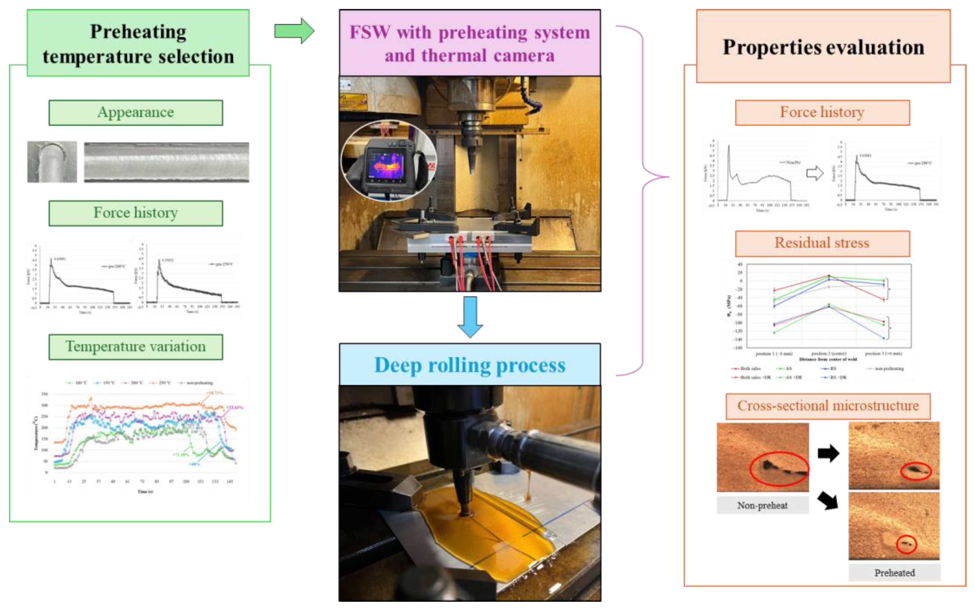
2. Materials and Methods
2.1. Workpiece Materials
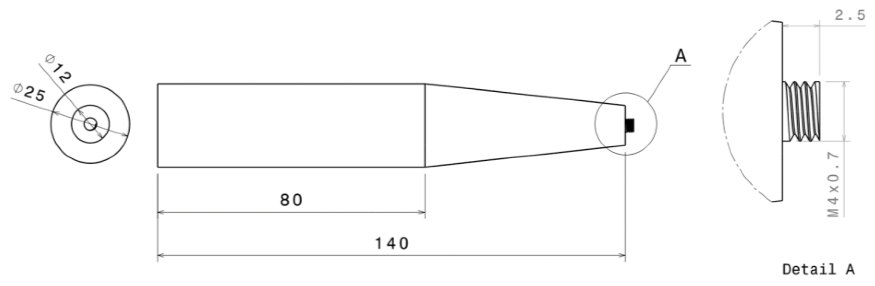
2.2. Friction Stir Welding (FSW)
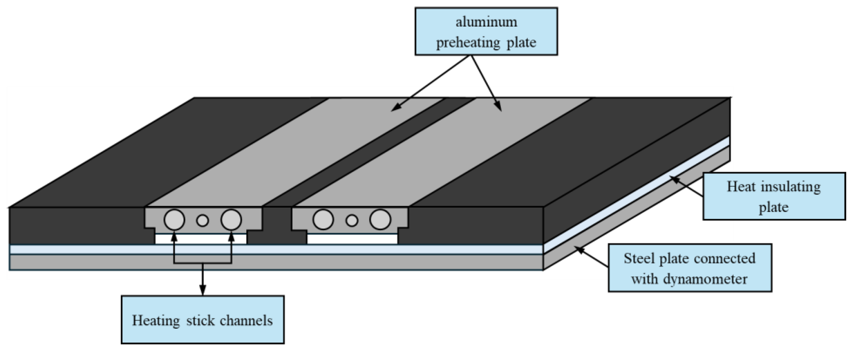
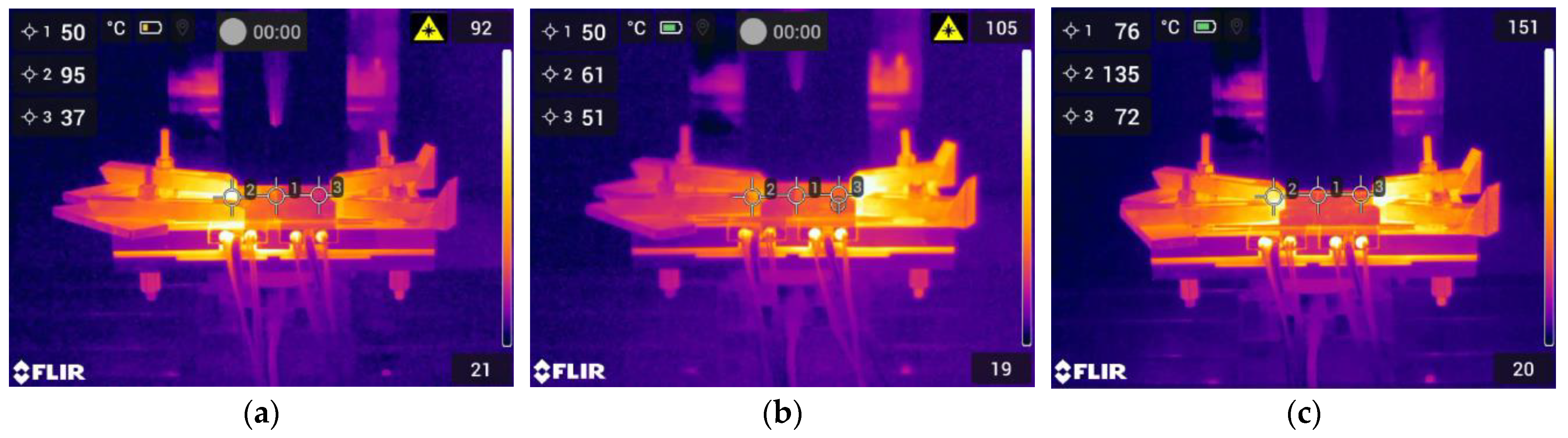
2.3. Preheating Process
2.4. Deep Rolling Process (DR)
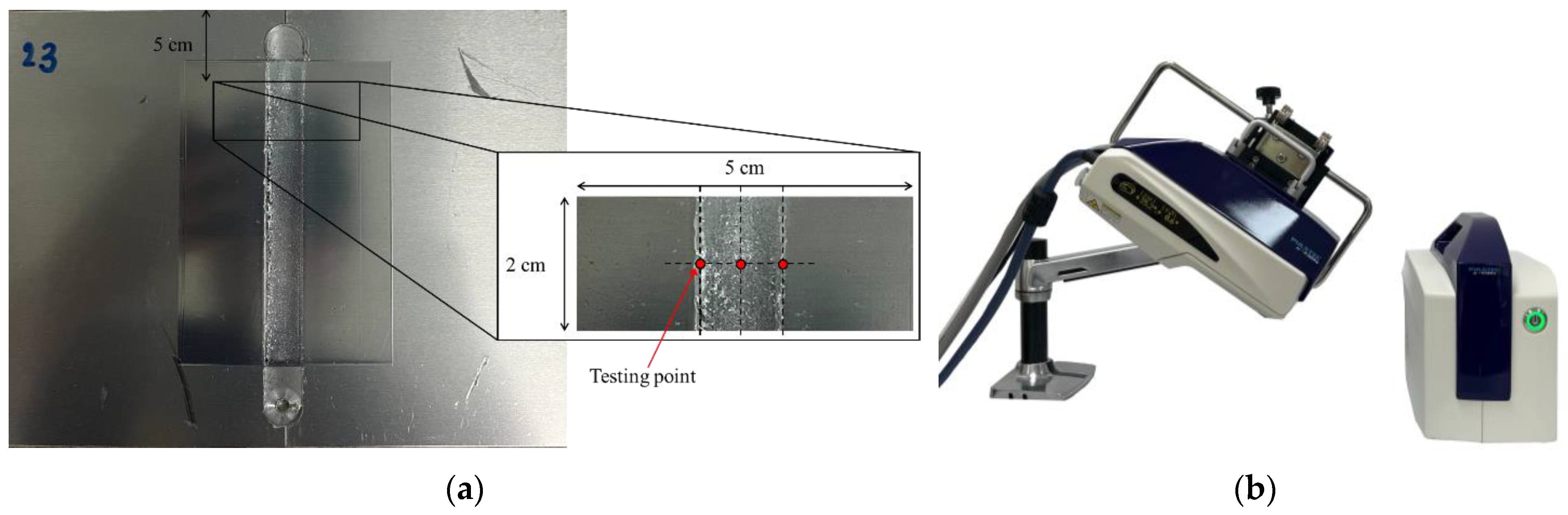
2.5. Mechanical Properties
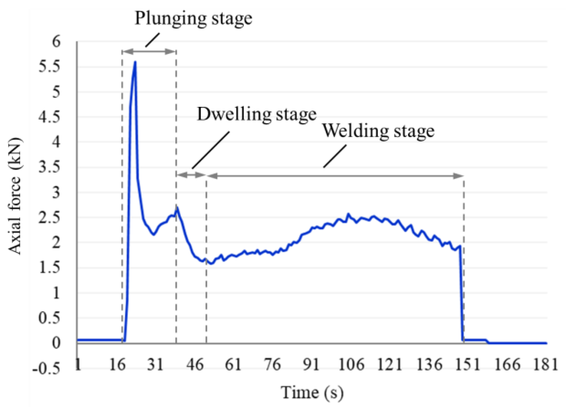
3. Results and Discussion
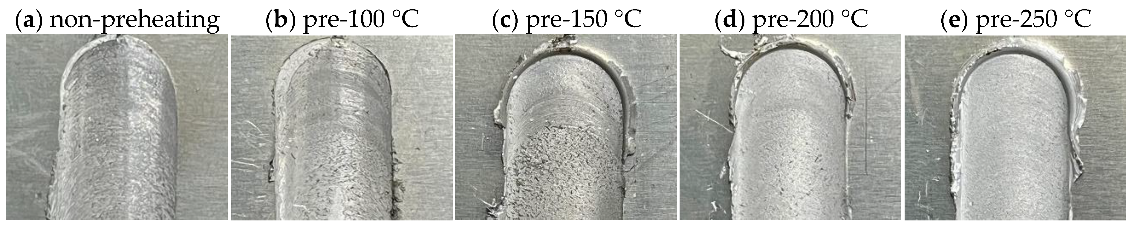
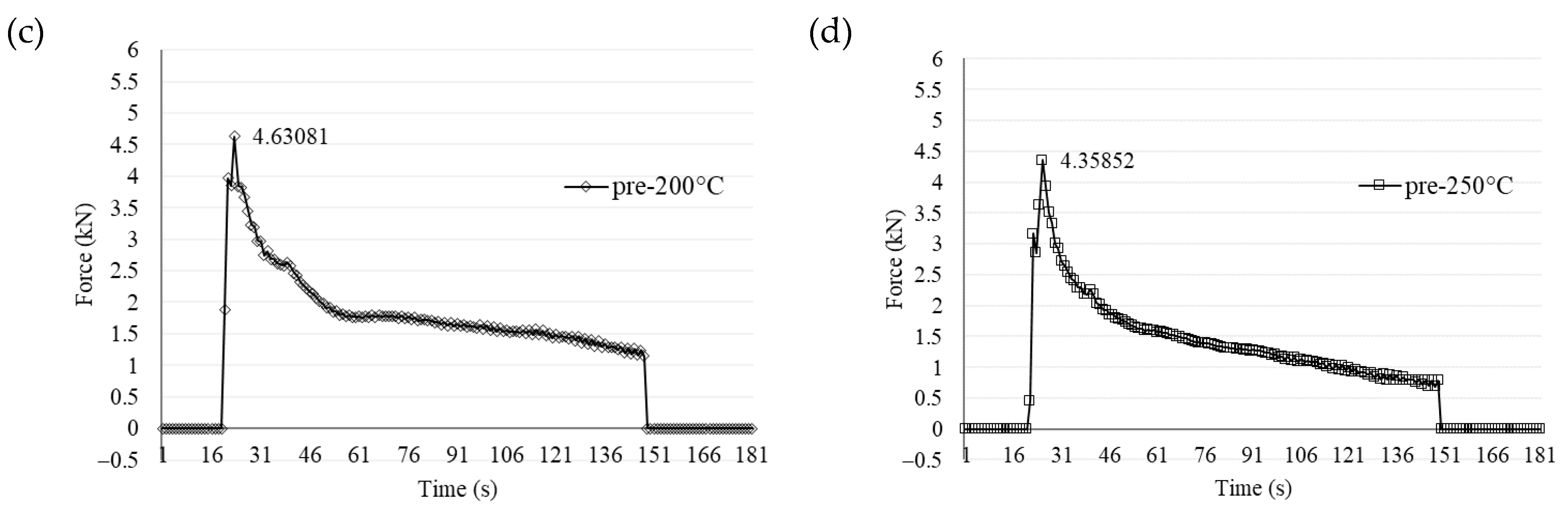
3.1. Results from Preheating Temperature Selection
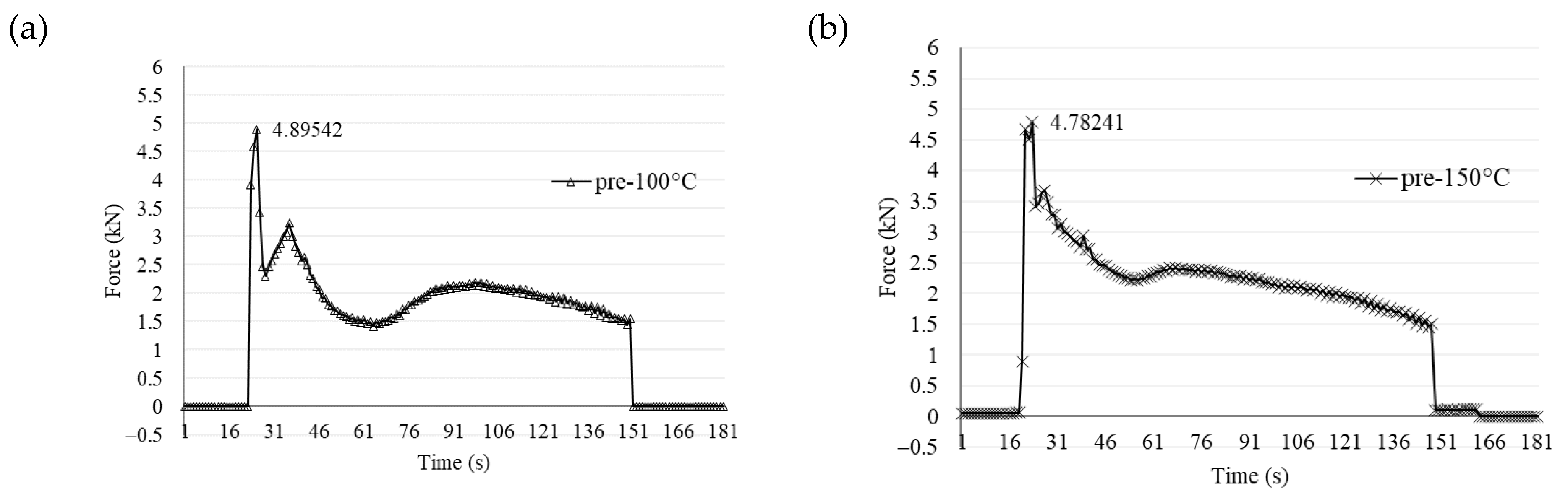
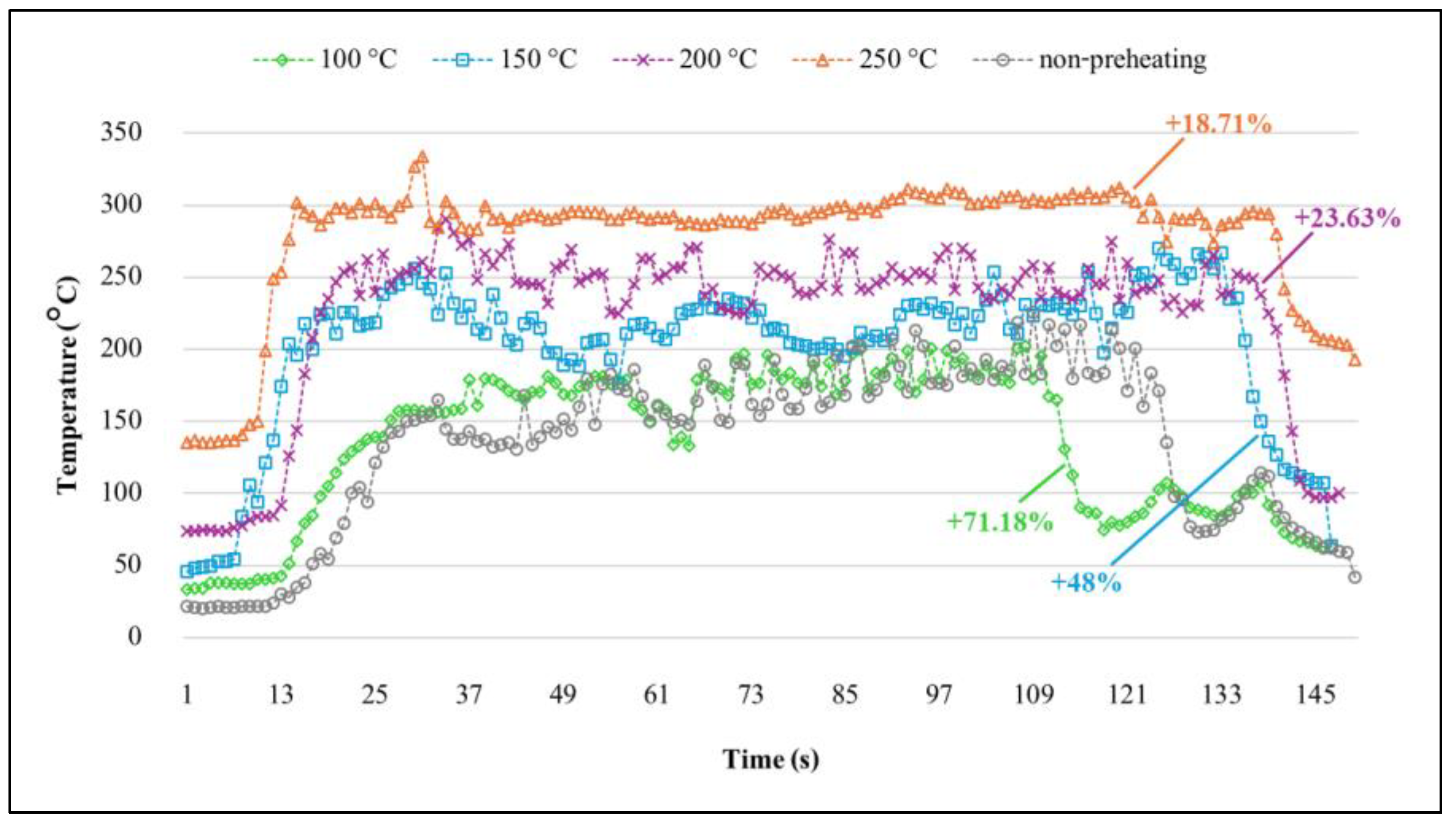
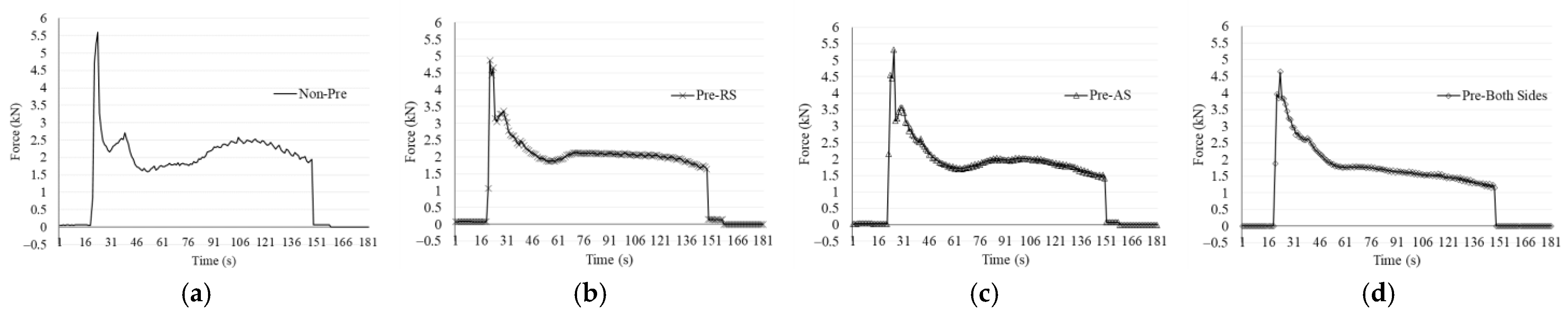
3.2. Influence of Preheating Positions on Thermal and Force Variations
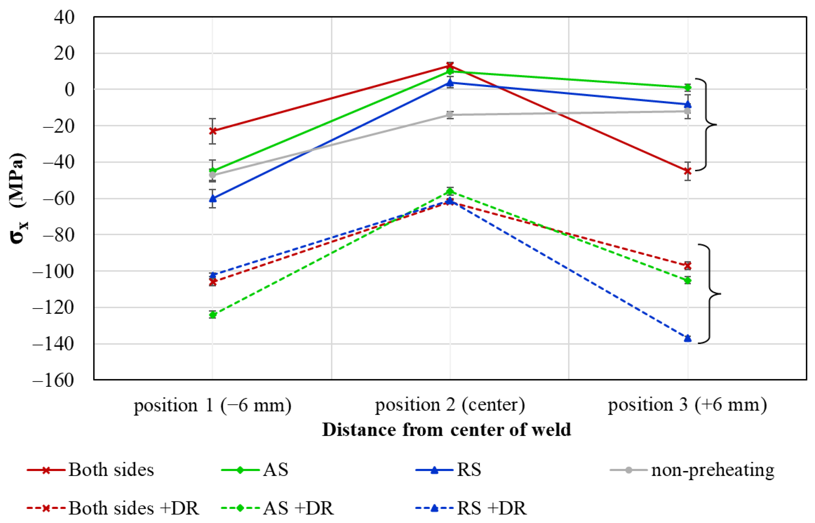
3.3. Residual Stress Distributions
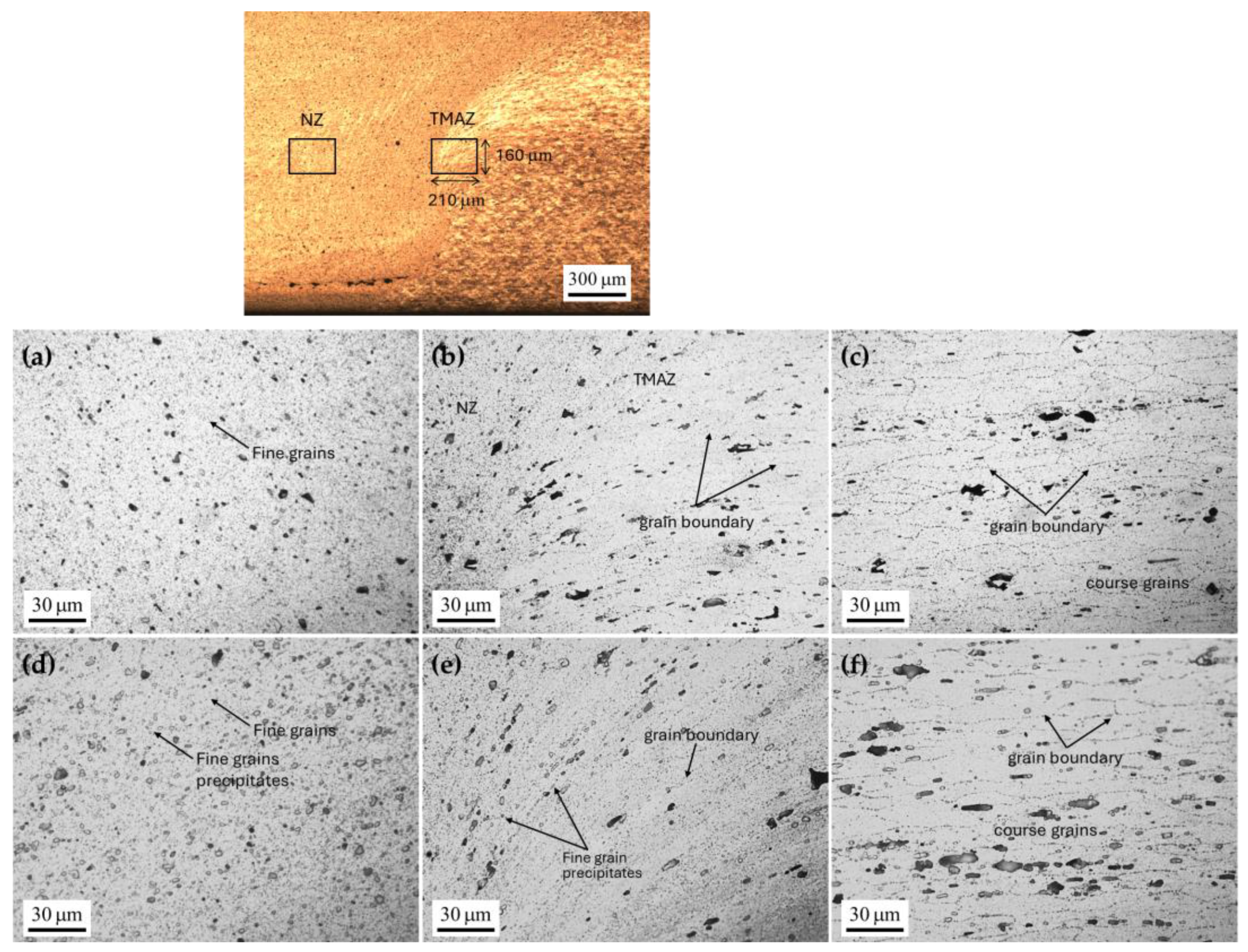
3.4. Microstructure Analysis
4. Conclusions
- Preheating at 100 °C, 150 °C, 200 °C, and 250 °C reduced the axial force required in the non-preheating condition by 7.33%, 5.84%, 30.24%, and 39.67%, respectively. Based on the observed appearance, force requirements, and achieved temperatures, a preheating temperature of 200 °C was identified as optimal.
- The back plate preheating assistance system provides a more substantial heat input, enhancing material flow and contributing to a reduction in tunnel defects. This system also facilitates deeper penetration of the tool pin end, particularly when preheating is applied to both sides.
- Preheating on the advancing side (AS) resulted in the smallest tunnel defect in the cross-sectional microstructure compared to preheating on the retreating side (RS) or both sides. Specifically, this preheating condition reduced tunnel defect size by 80.15% on the RS and 96.91% on the AS.
- A significant percentage difference in residual stress was observed at the right shoulder under the preheated AS condition, where residual stress changed from 1 MPa to −105 MPa after applying deep rolling pressure. The most compressive residual stress of −137 MPa was observed at the right shoulder under preheating on the AS; however, the effect of preheating was found to be negligible.
- The application of DR post-preheating positively impacted the reduction of tunnel defects. However, its effectiveness was limited by the proximity of the defect to the surface. DR post-preheating on the AS produced the most significant reduction in tunnel defects, decreasing them by approximately 97.85% on the RS and 97.82% on the AS. This improvement exceeded that achieved through preheating alone by 17.7% on the RS and 0.91% on the AS.
- Preheating had a significant effect on the nugget zone, leading to the formation of finer grains and a notable reduction in grain size in the nugget zone under preheated conditions.
- This study highlights the significant effects of preheating assistance, providing insights into the system’s capabilities and configurations to guide future applications and developments. Consequently, preheating techniques can be adapted for various industries by adjusting the heat source to meet specific operational needs. Additionally, investigating dissimilar materials with the preheating system is valuable for exploring optimal conditions and understanding the effects of preheating on different materials.
Author Contributions
Funding
Institutional Review Board Statement
Informed Consent Statement
Data Availability Statement
Acknowledgments
Conflicts of Interest
References
- Mishra, R.S.; Ma, Z. Friction stir welding and processing. Mater. Sci. Eng. R Rep. 2005, 50, 1–78. [Google Scholar] [CrossRef]
- Trimble, D.; Monaghan, J.; O’donnell, G. Force generation during friction stir welding of AA2024-T3. CIRP Ann. 2012, 61, 9–12. [Google Scholar] [CrossRef]
- Motalleb-Nejad, P.; Saeid, T.; Heidarzadeh, A.; Darzi, K.; Ashjari, M. Effect of tool pin profile on microstructure and mechanical properties of friction stir welded AZ31B magnesium alloy. Mater. Des. 2014, 59, 221–226. [Google Scholar] [CrossRef]
- Verma, S.; Gupta, M.; Misra, J.P. Effect of Preheating and Water Cooling on the Performance of Friction-Stir-Welded Aviation-Grade Aluminum Alloy Joints. J. Mater. Eng. Perform. 2019, 28, 4209–4220. [Google Scholar] [CrossRef]
- Ji, S.; Li, Z.; Wang, Y.; Ma, L. Joint formation and mechanical properties of back heating assisted friction stir welded Ti–6Al–4V alloy. Mater. Des. 2017, 113, 37–46. [Google Scholar] [CrossRef]
- Takehiko, T.; Yoshinori, S.; Yuuta, K.; Riichi, S.; Junichi, K.; Susumu, H. Numerical analysis of pre-heating by solid friction process: A study on friction stir welding with heating. Weld. Int. 2010, 24, 620–626. [Google Scholar] [CrossRef]
- Kim, J.-Y.; Jung, W.-S.; Lee, W.-S.; Byeon, J.-W. Surface modification of cast inconel 740 superalloy by heat-assisted friction stir processing. Met. Mater. Int. 2016, 22, 694–699. [Google Scholar] [CrossRef]
- Sun, Y.; Konishi, Y.; Kamai, M.; Fujii, H. Microstructure and mechanical properties of S45C steel prepared by laser-assisted friction stir welding. Mater. Des. 2013, 47, 842–849. [Google Scholar] [CrossRef]
- Song, K.H.; Tsumura, T.; Nakata, K. Development of Microstructure and Mechanical Properties in Laser-FSW Hybrid Welded Inconel 600. Mater. Trans. 2009, 50, 1832–1837. [Google Scholar] [CrossRef]
- Wada, T.; Morisada, Y.; Sun, Y.; Fujii, H.; Kawahito, Y.; Matsushita, M.; Ikeda, R. Friction Stir Welding of Medium Carbon Steel with Laser-Preheating. ISIJ Int. 2020, 60, 153–159. [Google Scholar] [CrossRef]
- Tiwari, A.; Pankaj, P.; Suman, S.; Singh, P.; Biswas, P.; Pal, S.; Rao, A.G. Effect of plasma preheating on weld quality and tool life during friction stir welding of DH36 steel. Proc. Inst. Mech. Eng. Part B J. Eng. Manuf. 2021, 235, 1458–1472. [Google Scholar] [CrossRef]
- Kumar, A.; Pankaj, P.; Biswas, P.; Rao, A.G. Finite Element Analysis and Experimental Investigation on Effect of Process Parameters in Plasma-Assisted Friction Stir Welding of Low Carbon Steel. Trans. Indian Inst. Met. 2022, 75, 2559–2579. [Google Scholar] [CrossRef]
- Pankaj, P.; Tiwari, A.; Biswas, P.; Rao, A.G. Plasma-Assisted Hybrid Dissimilar Friction Stir Welding for Joining of DH36 Steel and AISI 1008 Steel: Thermal Modelling and Experimental Analysis. Arab. J. Sci. Eng. 2021, 46, 7929–7952. [Google Scholar] [CrossRef]
- Raj, S.; Biswas, P. Experimental investigation of the effect of induction preheating on the microstructure evolution and corrosion behaviour of dissimilar FSW (IN718 and SS316L) joints. J. Manuf. Process. 2023, 95, 143–159. [Google Scholar] [CrossRef]
- Muhayat, N.; Harjono, M.S.; Depari, Y.P.D.S.; Prabowo, A.R.; Triyono, T.; Putri, E.D.W.S.; Tuswan, T. Friction Stir Welded AA5052-H32 under Dissimilar Pin Profile and Preheat Temperature: Microstructural Observations and Mechanical Properties. Metals 2021, 12, 4. [Google Scholar] [CrossRef]
- Lotfi, A.H.; Nourouzi, S. Predictions of the optimized friction stir welding process parameters for joining AA7075-T6 aluminum alloy using preheating system. Int. J. Adv. Manuf. Technol. 2014, 73, 1717–1737. [Google Scholar] [CrossRef]
- Wang, H.; Song, G.; Tang, G. Evolution of surface mechanical properties and microstructure of Ti 6Al 4V alloy induced by electropulsing-assisted ultrasonic surface rolling process. J. Alloy. Compd. 2016, 681, 146–156. [Google Scholar] [CrossRef]
- Zhao, J.; Liu, Z.; Chen, L.; Hua, Y. Ultrasonic-Induced Phase Redistribution and Acoustic Hardening for Rotary Ultrasonic Roller Burnished Ti-6Al-4V. Met. Mater. Trans. A 2019, 51, 1320–1333. [Google Scholar] [CrossRef]
- Withers, P.J. Residual stress and its role in failure. Rep. Prog. Phys. 2007, 70, 2211–2264. [Google Scholar] [CrossRef]
- Baisukhan, A.; Nakkiew, W. Enhancing surface integrity in friction stir welding through deep rolling and post-weld heat treatment. J. Adv. Join. Process. 2024, 9, 100223. [Google Scholar]
- Maawad, E.; Brokmeier, H.G.; Wagner, L.; Sano, Y.; Genzel, C. Investigation on the surface and near-surface characteristics of Ti–2.5 Cu after various mechanical surface treatments. Surf. Coat. Technol. 2011, 205, 3644–3650. [Google Scholar] [CrossRef]
- Sattari, S.; Atrian, A. Investigation of deep rolling effects on the fatigue life of Al–SiC nanocomposite. Mater. Res. Express 2018, 5, 015052. [Google Scholar] [CrossRef]
- Chu, Q.; Li, W.; Wu, D.; Liu, X.; Hao, S.; Zou, Y.; Yang, X.; Vairis, A. In-depth understanding of material flow behavior and refinement mechanism during bobbin tool friction stir welding. Int. J. Mach. Tools Manuf. 2021, 171, 103816. [Google Scholar] [CrossRef]
- Li, G.; Zhou, L.; Luo, S.; Dong, F.; Guo, N. Quality improvement of bobbin tool friction stir welds in Mg-Zn-Zr alloy by adjusting tool geometry. J. Mech. Work. Technol. 2020, 282, 116685. [Google Scholar] [CrossRef]
- Nandan, R.; DebRoy, T.; Bhadeshia, H. Recent advances in friction-stir welding–process, weldment structure and properties. Prog. Mater. Sci. 2008, 53, 980–1023. [Google Scholar] [CrossRef]
- Bhadeshia, H. Joining of commercial aluminium alloys. In Proceedings of the International Conference on Aluminium (INCAL ‘03), Aluminium Association of India, Bangalore, New Delhi, India, 23–25 April 2003; Aluminium Association of India: Bengaluru, India, 2003; Volume 3, pp. 195–203. [Google Scholar]
- Khan, N.Z.; Siddiquee, A.N.; Khan, Z.A.; Shihab, S.K. Investigations on tunneling and kissing bond defects in FSW joints for dissimilar aluminum alloys. J. Alloy. Compd. 2015, 648, 360–367. [Google Scholar] [CrossRef]
- Rasti, J. Study of the welding parameters effect on the tunnel void area during friction stir welding of 1060 aluminum alloy. Int. J. Adv. Manuf. Technol. 2018, 97, 2221–2230. [Google Scholar] [CrossRef]
- Balos, S.; Sidjanin, L. Effect of tunneling defects on the joint strength efficiency obtained with FSW. Mater. Tehnol. 2014, 48, 491–496. [Google Scholar]
- Kaewkham, P.; Nakkiew, W.; Baisukhan, A. Mechanical Properties Enhancement of Dissimilar AA6061-T6 and AA7075-T651 Friction Stir Welds Coupled with Deep Rolling Process. Materials 2022, 15, 6275. [Google Scholar] [CrossRef]
- Insua, P.; Nakkiew, W.; Wisittipanich, W. Post Weld Heat Treatment Optimization of Dissimilar Friction Stir Welded AA2024-T3 and AA7075-T651 Using Machine Learning and Metaheuristics. Materials 2023, 16, 2081. [Google Scholar] [CrossRef]
- Liu, X.; Xie, P.; Wimpory, R.; Li, W.; Lai, R.; Li, M.; Chen, D.; Liu, Y.; Zhao, H. Residual Stress, Microstructure and Mechanical Properties in Thick 6005A-T6 Aluminium Alloy Friction Stir Welds. Metals 2019, 9, 803. [Google Scholar] [CrossRef]
- Taira, S.; Tanaka, K.; Yamasaki, T. A method of X-ray microbeam measurement of local stress and its application to fatigue crack growth problems. J. Soc. Mater. Sci. 1978, 27, 251–256. [Google Scholar] [CrossRef]
- Sasaki, T. New Generation X-Ray Stress Measurement Using Debye Ring Image Data by Two-Dimensional Detection. Mater. Sci. Forum 2014, 783–786, 2103–2108. [Google Scholar] [CrossRef]
- Lu, X.; Qiao, J.; Qian, J.; Sun, S.; Liang, S.Y. Welding parameters optimization during plunging and dwelling phase of FSW 2219 aluminum alloy thick plate. Int. J. Adv. Manuf. Technol. 2022, 120, 6163–6173. [Google Scholar] [CrossRef]
- Garg, A.; Bhattacharya, A. Friction stir spot welding of AA6061-T6 and Cu with preheating: Strength and failure behavior at different test temperatures. Int. J. Adv. Manuf. Technol. 2020, 108, 1613–1629. [Google Scholar] [CrossRef]
- Shahi, P.; Barmouz, M.; Asadi, P. Force and torque in friction stir welding. In Advances in Friction Stir Welding and Processing; Elsevier: Amsterdam, The Netherlands, 2014; pp. 459–498. [Google Scholar]
- Jain, R.; Pal, S.K.; Singh, S.B. A study on the variation of forces and temperature in a friction stir welding process: A finite element approach. J. Manuf. Process. 2016, 23, 278–286. [Google Scholar] [CrossRef]
- Saha, R.; Biswas, P. Thermomechanical analysis of induction assisted friction stir welding of Inconel 718 alloy: A finite element approach. Int. J. Press. Vessel. Pip. 2022, 199, 104731. [Google Scholar] [CrossRef]
- Yaduwanshi, D.K.; Bag, S.; Pal, S. Effect of Preheating in Hybrid Friction Stir Welding of Aluminum Alloy. J. Mater. Eng. Perform. 2014, 23, 3794–3803. [Google Scholar] [CrossRef]
- Garg, A.; Raturi, M.; Bhattacharya, A. Influence of additional heating in friction stir welding of dissimilar aluminum alloys with different tool pin profiles. Int. J. Adv. Manuf. Technol. 2019, 105, 155–175. [Google Scholar] [CrossRef]
- Salih, O.S.; Ou, H.; Sun, W. Heat generation, plastic deformation and residual stresses in friction stir welding of aluminium alloy. Int. J. Mech. Sci. 2023, 238, 107827. [Google Scholar] [CrossRef]
- Schubnell, J.; Farajian, M. Fatigue improvement of aluminium welds by means of deep rolling and diamond burnishing. Weld. World 2021, 66, 699–708. [Google Scholar] [CrossRef]
- Morisada, Y.; Imaizumi, T.; Fujii, H. Clarification of material flow and defect formation during friction stir welding. Sci. Technol. Weld. Join. 2015, 20, 130–137. [Google Scholar] [CrossRef]
- Sevvel, P.; Jaiganesh, V. Effects of axial force on the mechanical properties of AZ80A Mg alloy during friction stir welding. Mater. Today Proc. 2017, 4, 1312–1320. [Google Scholar] [CrossRef]
- Aldanondo, E.; Vivas, J.; Álvarez, P.; Hurtado, I. Effect of Tool Geometry and Welding Parameters on Friction Stir Welded Lap Joint Formation with AA2099-T83 and AA2060-T8E30 Aluminium Alloys. Metals 2020, 10, 872. [Google Scholar] [CrossRef]
- Guo, C.; Shen, Y.; Hou, W.; Yan, Y.; Huang, G.; Liu, W. Effect of groove depth and plunge depth on microstructure and mechanical properties of friction stir butt welded AA6061-T6. J. Adhes. Sci. Technol. 2018, 32, 2709–2726. [Google Scholar] [CrossRef]
- Rathee, S.; Maheshwari, S.; Siddiquee, A.N.; Srivastava, M. Effect of tool plunge depth on reinforcement particles distribution in surface composite fabrication via friction stir processing. Def. Technol. 2017, 13, 86–91. [Google Scholar] [CrossRef]
- Ajri, A.; Rohatgi, N.; Shin, Y.C. Analysis of defect formation mechanisms and their effects on weld strength during friction stir welding of Al 6061-T6 via experiments and finite element modeling. Int. J. Adv. Manuf. Technol. 2020, 107, 4621–4635. [Google Scholar] [CrossRef]
- Nagarajan, B.; Kumar, D.; Fan, Z.; Castagne, S. Effect of deep cold rolling on mechanical properties and microstructure of nickel-based superalloys. Mater. Sci. Eng. A 2018, 728, 196–207. [Google Scholar] [CrossRef]
- Beghini, M.; Bertini, L.; Monelli, B.; Santus, C.; Bandini, M. Experimental parameter sensitivity analysis of residual stresses induced by deep rolling on 7075-T6 aluminium alloy. Surf. Coatings Technol. 2014, 254, 175–186. [Google Scholar] [CrossRef]


| Element | Mg | Fe | Si | Zn | Cr | Ti | Cu | Al |
|---|---|---|---|---|---|---|---|---|
| 6061 | 0.867 | 0.778 | 0.746 | 0.241 | 0.094 | 0.035 | 0.062 | Bal. |
| Parameter | Unit | Value |
|---|---|---|
| Welding speed | mm/min | 65 |
| Plunge depth | mm | 2.75 |
| rotational speed | rpm | 980 |
| Tool type | - | cylindrical threaded tool |
| Temperature collecting time | min. | 3 |
| Camera resolution | pixels | 640 × 480 |
| Frame rate | Hz | 30 |
| Parameter | Unit | Value |
|---|---|---|
| Ball type | - | HG6 |
| Ball diameter | mm | 6 |
| Feed rate | rpm | 1400 |
| Pressure | bar | 150 |
| Oil flow rate | liters/min. | 2 |
| No. | Preheating | Deep Rolling | |
|---|---|---|---|
| Advancing Side | Retreating Side | ||
| 1 | − | − | − |
| 2 | + | − | − |
| 3 | − | + | − |
| 4 | + | + | − |
| 5 | + | + | + |
| 6 | + | − | + |
| 7 | − | + | + |
| Condition | Appearance |
|---|---|
| Non-preheating | 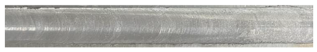 |
| 100 °C | 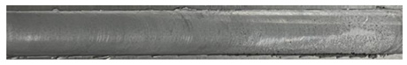 |
| 150 °C | 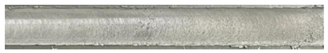 |
| 200 °C |  |
| 250 °C | 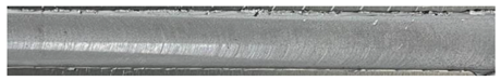 |
| Preheated Side | Residual Stress (MPa) | |||
|---|---|---|---|---|
| Deep Rolling | Position 1 (−6 mm) | Position 2 (Center) | Position 3 (+6 mm) | |
| advancing side (AS) | No | −45 ± 6 | 10 ± 1 | 1 ± 2 |
| Yes | −124 ± 2 | −56 ± 2 | −105 ± 2 | |
| % difference | 175.56% | 660.00% | 10,600.00% | |
| retreating side (RS) | No | −60 ± 5 | 4 ± 3 | −8 ± 5 |
| Yes | −102 ± 2 | −61 ± 2 | −137 ± 2 | |
| % difference | 70.00% | 1625.00% | 1612.50% | |
| both sides | No | −23 ± 7 | 13 ± 2 | −45 ± 5 |
| Yes | −106 ± 2 | −62 ± 1 | −97 ± 2 | |
| % difference | 360.87% | 576.92% | 115.56% | |
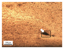
| Retreating Side (RS) | Advancing Side (AS) | Observation |
|---|---|---|
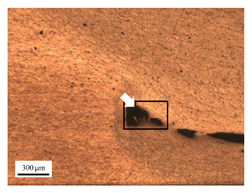 (non-preheated) | 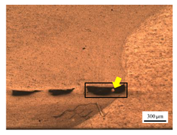 (non-preheated) | (1) Non-preheating: Significant tunnel defects were observed across the width of the pin tool at the bottom of the stir zone. These defects are attributed to insufficient material flow and inadequate heat generation, consistent with findings from previous studies [44,45]. The largest tunnel defect on the RS measured 0.0325 mm², as indicated by the white arrow, while the most significant defect on the AS measured 0.0551 mm², as marked by the yellow arrow. |
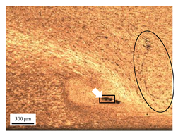
 (preheated) | 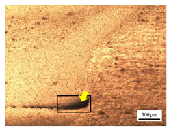 (non-preheated) | (2) Preheating on RS: the material flow on the RS is more pronounced compared to the as-welded specimen, likely due to the increased heat input, resulting in a reduced tunnel defect size of 0.0158 mm². On the AS, a tunnel defect measuring 0.0281 mm² is attributed to insufficient heat input. Additionally, the distance between the bottom surface and the tool end on the AS is reduced. |
 (non-preheated) | 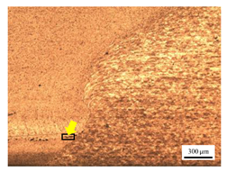 (preheated) | (3) Preheating on AS: a grain bond was identified within the circular symbol, accompanied by a tunnel on the RS and several smaller tunnels on the AS. The tunnel on the RS measured 0.0065 mm², as pointed by the white arrow. While on the AS, the defects measured 0.0017 mm², as pointed by the yellow arrow. The increased heat input on the AS facilitated enhanced metal flow, surpassing the effects of preheating on the RS. |
 (preheated) | 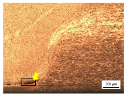 (preheated) | (4) Preheating both sides: the tunnel defect on the AS measured 0.0046 mm². On the RS, the tunnel size was 0.0036 mm². The tool end penetrated deepest compared to the preheating conditions on the AS (2) or the RS (3), and it appears symmetric on both the left and right sides. The material flow is well-distributed on both the RS and AS, with narrow holes detected below the tool outline. |
 (preheated) | 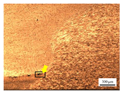 (non-preheated) | (5) Preheating RS with DR: compared to condition (2), the holes are smaller and closer together due to the effects of the deep rolling process. The tunnel defect on the RS measured 0.0014 mm², as indicated by the white arrow, while the size on the AS was 0.0018 mm², as indicated by the yellow arrow. However, a cold lap defect was observed on the RS (indicated by the white dashed line), attributed to insufficient flow and mixing of the plasticized metal [46]. |
 (non-preheated) | 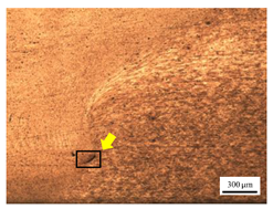 (preheated) | (6) Preheating AS with DR: small tunnels were detected only at the corners of the tool outline (indicated by red arrows). No cracks or other grooves were observed. The metal contact at the bottom part is nearly homogeneous. The tunnel defect on the RS (indicated by the white arrow) measured 0.0007 mm², while the size on the AS (indicated by the yellow arrow) was 0.0012 mm². |
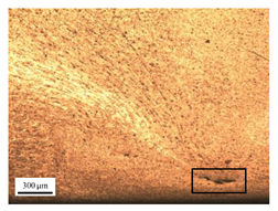
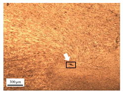
 (preheated) |  (preheated) | (7) Preheating both sides with DR: a narrow tunnel was observed at the bottom of the nugget zone on the RS. Several small tunnels were identified at the interface between the tool outline and the underlying metal. The size of the tunnel defects remained unchanged by the application of deep rolling. The tunnel defect on the RS (indicated by the white arrow) measured 0.0045 mm², but on the AS, various small holes were observed. |
Disclaimer/Publisher’s Note: The statements, opinions and data contained in all publications are solely those of the individual author(s) and contributor(s) and not of MDPI and/or the editor(s). MDPI and/or the editor(s) disclaim responsibility for any injury to people or property resulting from any ideas, methods, instructions or products referred to in the content. |
© 2024 by the authors. Licensee MDPI, Basel, Switzerland. This article is an open access article distributed under the terms and conditions of the Creative Commons Attribution (CC BY) license (https://creativecommons.org/licenses/by/4.0/).
Share and Cite
Insua, P.; Nakkiew, W.; Baisukhan, A.; Pitjamit, S. Effect of Back Plate Preheating Assistance System and Deep Rolling Process on Microstructure Defects and Axial Force Reduction of Friction Stir Welded AA6061 Joint. Materials 2024, 17, 4447. https://doi.org/10.3390/ma17184447
Insua P, Nakkiew W, Baisukhan A, Pitjamit S. Effect of Back Plate Preheating Assistance System and Deep Rolling Process on Microstructure Defects and Axial Force Reduction of Friction Stir Welded AA6061 Joint. Materials. 2024; 17(18):4447. https://doi.org/10.3390/ma17184447
Chicago/Turabian StyleInsua, Pinmanee, Wasawat Nakkiew, Adirek Baisukhan, and Siwasit Pitjamit. 2024. "Effect of Back Plate Preheating Assistance System and Deep Rolling Process on Microstructure Defects and Axial Force Reduction of Friction Stir Welded AA6061 Joint" Materials 17, no. 18: 4447. https://doi.org/10.3390/ma17184447
APA StyleInsua, P., Nakkiew, W., Baisukhan, A., & Pitjamit, S. (2024). Effect of Back Plate Preheating Assistance System and Deep Rolling Process on Microstructure Defects and Axial Force Reduction of Friction Stir Welded AA6061 Joint. Materials, 17(18), 4447. https://doi.org/10.3390/ma17184447