
Influence of the Metallic Sublayer on Corrosion Resistance in Hanks’ Solution of 316L Stainless Steel Coated with Diamond-like Carbon

 , , and
Abstract
:1. Introduction
2. Materials and Methods
2.1. Sample Preparation
2.2. Sample Characterisation
3. Results and Discussion
4. Conclusions
Author Contributions
Funding
Institutional Review Board Statement
Informed Consent Statement
Data Availability Statement
Acknowledgments
Conflicts of Interest
References
- Lodhi, M.J.K.; Deen, K.M.; Greenlee-Wacker, M.C.; Haider, W. Additively manufactured 316L stainless steel with improved corrosion resistance and biological response for biomedical applications. Addit. Manuf. 2019, 27, 8–19. [Google Scholar] [CrossRef]
- Silva, R.N.A.; Neto, R.; Vieira, A.; Leite, P.; Radi, P.; da Silveira, C.H.; Santos, M.D.; Viana, F.; Vieira, L. Wear Rate, Tribo-Corrosion, and Plastic Deformation Values of Co-Cr-Mo Alloy in Ringer Lactate Solution. Materials 2024, 17, 2327. [Google Scholar] [CrossRef] [PubMed]
- Rahmouni, K.; Besnard, A.; Oulmi, K.; Nouveau, C.; Hidoussi, A.; Aissani, L.; Zaabat, M. In vitro corrosion response of CoCrMo and Ti-6Al-4V orthopedic implants with Zr columnar thin films. Surf. Coat. Technol. 2022, 436, 128310. [Google Scholar] [CrossRef]
- Mantripragada, V.P.; Lecka-Czernik, B.; Ebraheim, N.A.; Jayasuriya, A.C. An overview of recent advances in designing orthopedic and craniofacial implants. J. Biomed. Mater. Res. Part A 2013, 101, 3349–3364. [Google Scholar] [CrossRef] [PubMed]
- Liu, Y.; Zhu, D.; Pierre, D.; Gilbert, J.L. Fretting initiated crevice corrosion of 316LVM stainless steel in physiological phosphate buffered saline: Potential and cycles to initiation. Acta Biomater. 2019, 97, 565–577. [Google Scholar] [CrossRef]
- Eliaz, N. Corrosion of metallic biomaterials: A review. Materials 2019, 12, 407. [Google Scholar] [CrossRef]
- Salem, K.H.; Lindner, N.; Tingart, M.; Elmoghazy, A.D. Severe metallosis-related osteolysis as a cause of failure after total knee replacement. J. Clin. Orthop. Trauma 2020, 11, 165–170. [Google Scholar] [CrossRef]
- Eltit, F.; Noble, J.; Sharma, M.; Benam, N.; Haegert, A.; Bell, R.H.; Simon, F.; Duncan, C.P.; Garbuz, D.S.; Greidanus, N.V.; et al. Cobalt ions induce metabolic stress in synovial fibroblasts and secretion of cytokines/chemokines that may be diagnostic markers for adverse local tissue reactions to hip implants. Acta Biomater. 2021, 131, 581–594. [Google Scholar] [CrossRef]
- Landek, D.; Kurtela, M.; Stojanovic, I.; Jacan, J.; Jakovljevic, S. Corrosion and micro-abrasion properties of an AISI 316L austenitic stainless steel after low-temperature plasma nitriding. Coatings 2023, 13, 1854. [Google Scholar] [CrossRef]
- Souza, R.M.; Ignat, M.; Pinedo, C.E.; Tschiptschin, A.P. Structure and properties of low temperature plasma carburized austenitic stainless steels. Surf. Coat. Technol. 2009, 204, 1102–1105. [Google Scholar] [CrossRef]
- Zhang, T.F.; Deng, Q.Y.; Liu, B.; Wu, B.J.; Jing, F.J.; Leng, Y.X.; Huang, N. Wear and corrosion properties of diamond like carbon (DLC) coating on stainless steel, CoCrMo and Ti6Al4V substrates. Surf. Coat. Technol. 2015, 273, 12–19. [Google Scholar] [CrossRef]
- Makowski, S.; Härtwig, F.; Soldera, M.; Ojeil, M.; Lorenz, L.; Kaulfuß, F.; Lasagni, A.F. Improved Tribological Performance of ta-C/MoSx Coatings Deposited on Laser Micro-Structured Steel Substrates in Both Vacuum and Air. Lubricants 2024, 12, 200. [Google Scholar] [CrossRef]
- Haenle, M.; Fritsche, A.; Zietz, C.; Bader, R.; Heidenau, F.; Mittelmeier, W.; Gollwitzer, H. An extended spectrum bactericidal titanium dioxide (TiO2) coating for metallic implants: In vitro effectiveness against MRSA and mechanical properties. J. Mater. Sci. Mater. Med. 2011, 22, 381–387. [Google Scholar] [CrossRef] [PubMed]
- Kaluđerović, M.R.; Schreckenbach, J.P.; Graf, H.-L. Zirconia coated titanium for implants and their interactions with osteoblast cells. Mater. Sci. Eng. C 2014, 44, 254–261. [Google Scholar] [CrossRef]
- Alves, C.F.A.; Cavaleiro, A.; Carvalho, S. Bioactivity response of Ta1−xOx coatings deposited by reactive DC magnetron sputtering. Mater. Sci. Eng. C 2016, 58, 110–118. [Google Scholar] [CrossRef]
- Malisz, K.; Świeczko-Żurek, B.; Sionkowska, A. Preparation and Characterization of Diamond-like Carbon Coatings for Biomedical Applications—A Review. Materials 2023, 16, 3420. [Google Scholar] [CrossRef]
- Wongpanya, P.; Pintitraratibodee, N.; Thumanu, K.; Euaruksakul, C. Improvement of corrosion resistance and biocompatibility of 316L stainless steel for joint replacement application by Ti-doped and Ti-interlayered DLC films. Surf. Coat. Technol. 2021, 425, 127734. [Google Scholar] [CrossRef]
- Cui, F.Z.; Li, D.J. A review of investigations on biocompatibility of diamond-like carbon and carbon nitride films. Surf. Coat. Technol. 2000, 131, 481–487. [Google Scholar] [CrossRef]
- Penkov, O.V.; Pukha, V.E.; Starikova, S.L.; Khadem, M.; Starikov, V.V.; Maleev, M.V.; Kim, D.-E. Highly wear-resistant and biocompatible carbon nanocomposite coatings for dental implants. Biomaterials 2016, 102, 130–136. [Google Scholar] [CrossRef]
- Rothammer, B.; Neusser, K.; Bartz, M.; Wartzack, S.; Schubert, A.; Marian, M. Evaluation of the wear-resistance of DLC-coated hard-on-soft pairings for biomedical applications. Wear 2023, 523, 204728. [Google Scholar] [CrossRef]
- Zheng, J.; Lu, Z.; Liu, S.; Ding, J.C.; Ran, S.; Sun, J. Microstructure and tribological behavior in ta-C films prepared by laser-induced filtered cathodic vacuum arc technique: Effect of charge voltage. Vacuum 2024, 219, 112745. [Google Scholar] [CrossRef]
- Zavaleyev, V.; Walkowicz, J.; Greczynski, G.; Hultman, L. Effect of substrate temperature on properties of diamond-like films deposited by combined DC impulse vacuum-arc method. Surf. Coat. Technol. 2013, 236, 444–449. [Google Scholar] [CrossRef]
- Wang, P.; Wang, X.; Xu, T.; Liu, W.; Zhang, J. Comparing internal stress in diamond-like carbon films with different structure. Thin Solid Films 2007, 515, 6899–6903. [Google Scholar] [CrossRef]
- Azzi, M.; Amirault, P.; Paquette, M.; Klemberg-Sapieha, J.E.; Martinu, L. Corrosion performance and mechanical stability of 316L/DLC coating system: Role of interlayers. Surf. Coat. Technol. 2010, 204, 3986–3994. [Google Scholar] [CrossRef]
- Chen, C.-C.; Hong, F.C.-N. Interfacial studies for improving the adhesion of diamond-like carbon films on steel. Appl. Surf. Sci. 2005, 243, 296–303. [Google Scholar] [CrossRef]
- Azzi, M.; Paquette, M.; Szpunara, J.A.; Klemberg-Sapieha, J.E.; Martin, L. Tribocorrosion behaviour of DLC-coated 316L stainless steel. Wear 2009, 267, 860–866. [Google Scholar] [CrossRef]
- Bocchetta, P.; Chen, L.-Y.; Tardelli, J.D.C.; Reis, A.C.d.; Almeraya-Calderón, F.; Leo, P. Passive Layers and Corrosion Resistance of Biomedical Ti-6Al-4V and β-Ti Alloys. Coatings 2021, 11, 487. [Google Scholar] [CrossRef]
- Grimm, W.; Weihnacht, V. Properties of super-hard carbon films deposited by pulsed arc process. Vacuum 2010, 85, 506–509. [Google Scholar] [CrossRef]
- McCafferty, E. Validation of corrosion rates measured by the Tafel extrapolation method. Corros. Sci. 2005, 47, 3202–3215. [Google Scholar] [CrossRef]
- Stern, M.; Geary, A.L. Electrochemical polarization I. A theoretical analysis of the shape of polarization curves. J. Electrochem. Soc. 1957, 104, 56–63. [Google Scholar] [CrossRef]
- Kim, H.-G.; Ahn, S.-H.; Kim, J.-G.; Park, S.J.; Lee, K.-R. Electrochemical behavior of diamond-like carbon films for biomedical applications. Thin Solid Films 2005, 475, 291–297. [Google Scholar] [CrossRef]
- Creus, J.; Mazille, H.; Idrissi, H. Porosity evaluation of protective coatings onto steel, through electrochemical techniques. Surf. Coat. Technol. 2000, 130, 224–232. [Google Scholar] [CrossRef]
- Warcholinski, B.; Gilewicz, A.; Myslinski, P.; Dobruchowska, E.; Murzynski, D.; Kuznetsova, T.A. Effect of Silicon Concentration on the Properties of Al-Cr-Si-N Coatings Deposited Using Cathodic Arc Evaporation. Materials 2020, 13, 4717. [Google Scholar] [CrossRef] [PubMed]
- Gilewicz, A.; Dobruchowska, E.; Murzynski, D.; Kuznetsova, T.A.; Lapitskaya, V.A.; Myslinski, P.; Warcholinski, B. Influence of the Chemical Composition of AlCrN Coatings on Their Mechanical, Tribological, and Corrosion Characteristics. J. Frict. Wear 2020, 41, 383–392. [Google Scholar] [CrossRef]
- Sobral, A.V.C.; Ristow, W., Jr.; Azambuja, D.S.; Costa, I.; Franco, C.V. Potentiodynamic tests and electrochemical impedance spectroscopy of injection molded 316L steel in NaCl solution. Corros. Sci. 2001, 43, 1019–1030. [Google Scholar] [CrossRef]
- Sun, Y.; Haruman, E. Tribocorrosion behaviour of low temperature plasma carburised 316L stainless steel in 0.5 M NaCl solution. Corros. Sci. 2011, 53, 4131–4140. [Google Scholar] [CrossRef]
- Ceschini, L.; Chiavari, C.; Lanzoni, E.; Martini, C. Low-temperature carburised AISI 316L austenitic stainless steel: Wear and corrosion behaviour. Mater. Des. 2012, 38, 154–160. [Google Scholar] [CrossRef]
- Dobruchowska, E.; Suszko, T.; Greczynski, G.; Adamczewska, D.; Gulbinski, W. Amorphous/quasi-amorphous CoCrMo-C coatings for improved electrochemical properties and tribocorrosion resistance of biomedical alloys. Surf. Coat. Technol. 2023, 460, 129398. [Google Scholar] [CrossRef]
- Wang, X.Y.; Wu, Y.S.; Zhang, L.; Yu, Z.Y. Atomic force microscopy and X-ray photoelectron spectroscopy study on the passive film for type 316L stainless steel. Corrosion 2001, 57, 540–546. [Google Scholar] [CrossRef]
- Kannan, S.; Balamurugan, A.; Rajeswari, S. Electrochemical characterization of hydroxyapatite coatings on HNO3 passivated 316L SS for implant applications. Electrochim. Acta 2005, 50, 2065–2072. [Google Scholar] [CrossRef]
- Lillard, R.S.; Butt, D.P.; Taylor, T.N.; Walter, K.C.; Nastasi, M. The breakdown mechanism of diamond-like carbon coated nickel in chloride solution. Corros. Sci. 1997, 39, 1605–1624. [Google Scholar] [CrossRef]
- Masami, I.; Setsuo, N.; Tsutomu, S.; Junho, C. Improvement of corrosion protection property of Mg-alloy by DLC and Si–DLC coatings with PBII technique and multi-target DC–RF magnetron sputtering. Nucl. Instrum. Methods Phys. Res. Sect. B 2009, 267, 1675–1679. [Google Scholar] [CrossRef]
- Wang, Q.; Zhou, F.; Zhou, Z.; Wang, C.; Zhang, W.; Li, L.K.-Y.; Lee, S.-T. Effect of titanium or chromium content on the electrochemicalproperties of amorphous carbon coatings in simulated body fluid. Electrochim. Acta 2013, 112, 603–611. [Google Scholar] [CrossRef]
- Hodgson, A.W.E.; Kurz, S.; Virtanen, S.; Fervel, V.; Olsson, C.-O.A.; Mischler, S. Passive and transpassive behaviour of CoCrMo in simulated biological solutions. Electrochim. Acta 2004, 49, 2167–2178. [Google Scholar] [CrossRef]
- Pourbaix, M. Significance of protection potential in pitting and intergranular corrosion. Corrosion 1970, 26, 431–438. [Google Scholar] [CrossRef]
- Figueira, N.; Silva, T.M.; Carmezima, M.J.; Fernandes, J.C.S. Corrosion behaviour of NiTi alloy. Electrochim. Acta 2009, 54, 921–926. [Google Scholar] [CrossRef]
- Peng, X.L.; Clyne, T.W. Mechanical stability of DLC films on metallic substrates. Part II Interfacial toughness, debonding and blistering. Thin Solid Films 1998, 312, 210–227. [Google Scholar] [CrossRef]
- Streletskiy, O.A.; Zavidovskiy, I.A.; Balabanyan, V.Y.; Tsiskarashvili, A.V. Antibacterial properties of modified a-C and ta-C coatings: The effects of the sp2/sp3 ratio, oxidation, nitridation, and silver incorporation. Appl. Phys. A 2022, 128, 929. [Google Scholar] [CrossRef]
- Wei, C.; Yen, J.-Y. Effect of film thickness and interlayer on the adhesion strength of diamond like carbon films on different substrates. Diamond Relat. Mater. 2007, 16, 1325–1330. [Google Scholar] [CrossRef]


| Element | C | Cr | Ni | Mo | Mn | S | P | Fe |
|---|---|---|---|---|---|---|---|---|
| Content wt.% | 0.021 | 17.6 | 12.45 | 2.29 | 1.05 | 0.002 | 0.031 | balance |
| Process Stage | Treatment Duration in One Step [s] | Pause Duration in One Step [s] | Number of Steps 1 | Ubias [V] 2 | pAr [Pa] 3 | Iarc [A] 4 | Ipulse [A] 5 |
|---|---|---|---|---|---|---|---|
| Etching with Cr ions | 120 | 60 | 5 | −500 | 0.4 | 100 | - |
| Deposition of Cr (or Ti) sublayer | 200 | 60 | 3 | −80/180 | 0.4 | 100 | - |
| Substrate cooling to 90 °C | 3600 | - | 1 | - | - | - | - |
| Etching with C ions | 60 | 60 | 2 | −500 | 0.01 | 50 | - |
| Etching with C ions | 90 | 60 | 1 | −500 | 0.01 | 50 | 1400 |
| Deposition of DLC coating | 30 | 60 | 6/12 | 0 | 0.01 | 50 | 1400 |
| Components | CaCl2 × 2H2O | MgSO4 | KCl | KH2PO4 | NaHCO3 | NaCl | NaH2PO4 | D-Glucose |
|---|---|---|---|---|---|---|---|---|
| Concentration [g/dm3] | 0.021 | 17.600 | 12.450 | 2.290 | 1.050 | 0.002 | 0.031 | balance |
| Electrochemical Parameter | Sample | ||||
|---|---|---|---|---|---|
| 316L | 316L/ Cr/0.2DLC | 316L/ Cr/0.5DLC | 316L/ Ti/0.2DLC | 316L/ Ti/0.5DLC | |
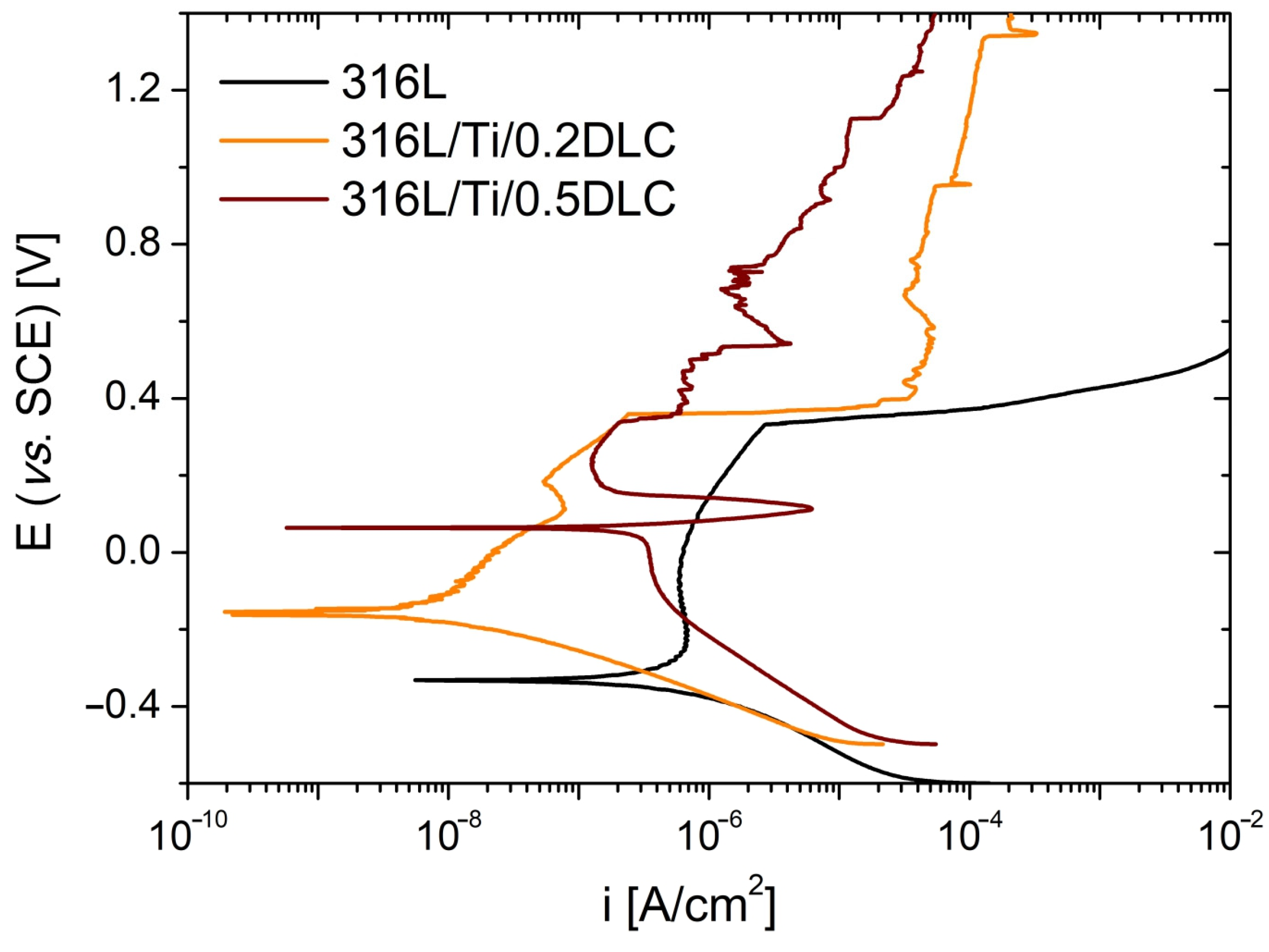
| Ecorr [V] | −0.334 | −0.185 | −0.178 | −0.154 | 0.061 |
| icorr [A/cm2] | 26.3 × 10⁻⁸ | 1.3 × 10⁻⁸ | 0.9 × 10⁻⁸ | 0.6 × 10⁻⁸ | 11.4 × 10⁻⁸ |
| -bc [V/dec] | 0.090 | 0.070 | 0.068 | 0.067 | 0.073 |
| ba [V/dec] | 0.146 | 0.126 | 0.122 | 0.153 | 0.023 |
| Rp [Ωcm2] | 92 × 103 | 1.49 × 10⁶ | 2.00 × 10⁶ | 4.70 × 10⁶ | 0.07 × 10⁶ |
| Eb [V] | 0.331 | 0.290 | 0.332 | 0.362 | - |
| P [%] | - | 0.59 | 0.39 | 0.11 | 0.26 |
Disclaimer/Publisher’s Note: The statements, opinions and data contained in all publications are solely those of the individual author(s) and contributor(s) and not of MDPI and/or the editor(s). MDPI and/or the editor(s) disclaim responsibility for any injury to people or property resulting from any ideas, methods, instructions or products referred to in the content. |
© 2024 by the authors. Licensee MDPI, Basel, Switzerland. This article is an open access article distributed under the terms and conditions of the Creative Commons Attribution (CC BY) license (https://creativecommons.org/licenses/by/4.0/).
Share and Cite
Dobruchowska, E.; Schulz, J.; Zavaleyev, V.; Walkowicz, J.; Suszko, T.; Warcholinski, B. Influence of the Metallic Sublayer on Corrosion Resistance in Hanks’ Solution of 316L Stainless Steel Coated with Diamond-like Carbon. Materials 2024, 17, 4487. https://doi.org/10.3390/ma17184487
Dobruchowska E, Schulz J, Zavaleyev V, Walkowicz J, Suszko T, Warcholinski B. Influence of the Metallic Sublayer on Corrosion Resistance in Hanks’ Solution of 316L Stainless Steel Coated with Diamond-like Carbon. Materials. 2024; 17(18):4487. https://doi.org/10.3390/ma17184487
Chicago/Turabian StyleDobruchowska, Ewa, Justyna Schulz, Viktor Zavaleyev, Jan Walkowicz, Tomasz Suszko, and Bogdan Warcholinski. 2024. "Influence of the Metallic Sublayer on Corrosion Resistance in Hanks’ Solution of 316L Stainless Steel Coated with Diamond-like Carbon" Materials 17, no. 18: 4487. https://doi.org/10.3390/ma17184487