


Microstructure and Hardness Properties of Additively Manufactured AISI 316L Welded by Tungsten Inert Gas and Laser Welding Techniques


Abstract
:1. Introduction
2. Materials and Methods
2.1. LPBF Specimen Manufacture and Heat Treatment
2.2. Welding Processes
2.2.1. TIG Welding Technique
Delta Ferrite Measurement
2.2.2. Laser Welding Technique
3. Mechanical Properties and Microstructure Evaluation
3.1. Microstructure Evaluation
3.2. Microhardness Measurements
4. Results and Discussion
4.1. Microstructure Characterization
4.1.1. Microstructure of BM
4.1.2. Microstructure of TIG-Welded Joints
Delta Ferrite Content
4.1.3. Laser-Welded Joints
4.2. Effect of Building Orientation on Cooling Rate
4.2.1. Effect of Building Orientation on Cooling Rate during Printing Process
4.2.2. Effect of Building Orientation on Cooling Rate during Welding Process
4.3. Hardness Results
4.3.1. TIG-Welded Joints
4.3.2. Laser-Welded Joints
4.4. Summary of Results
5. Applications and Future Prospectives
6. Conclusions
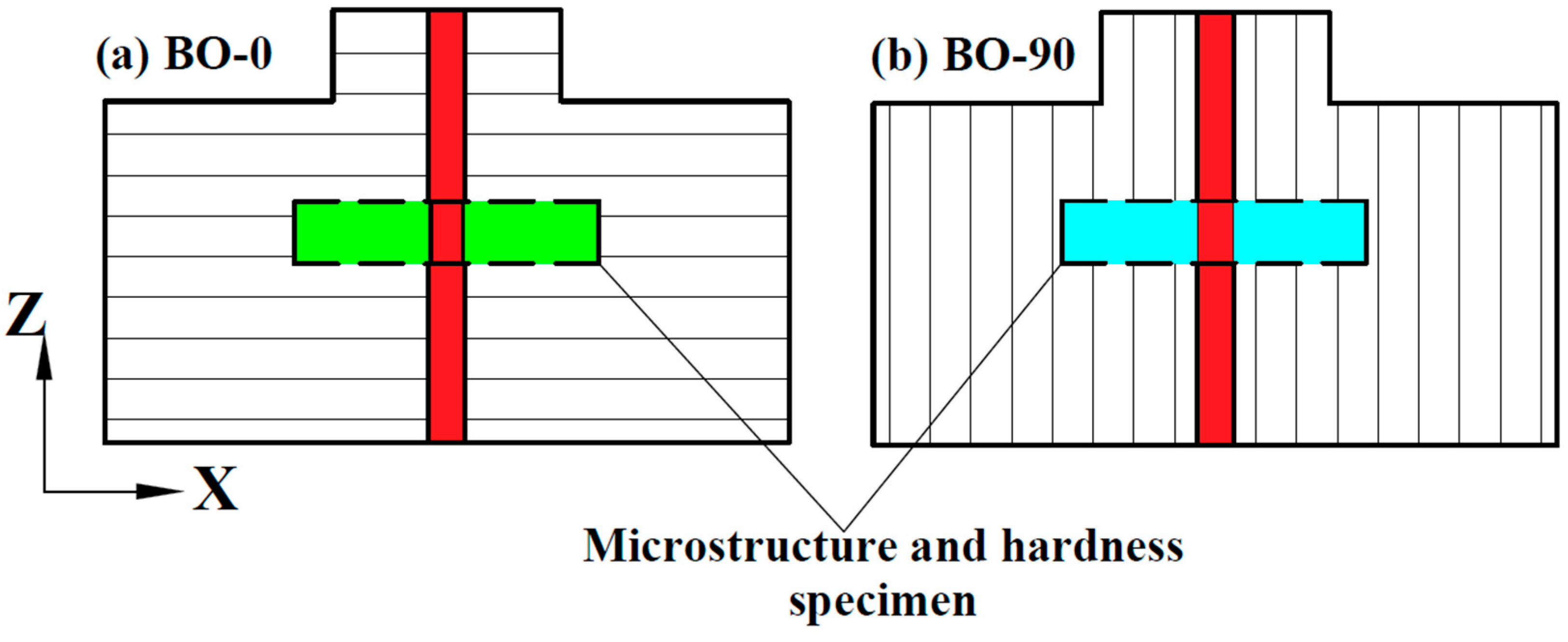
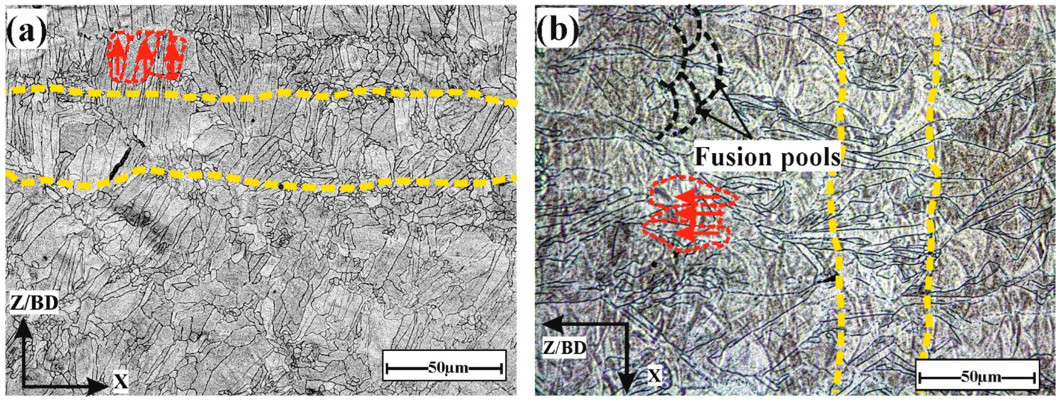
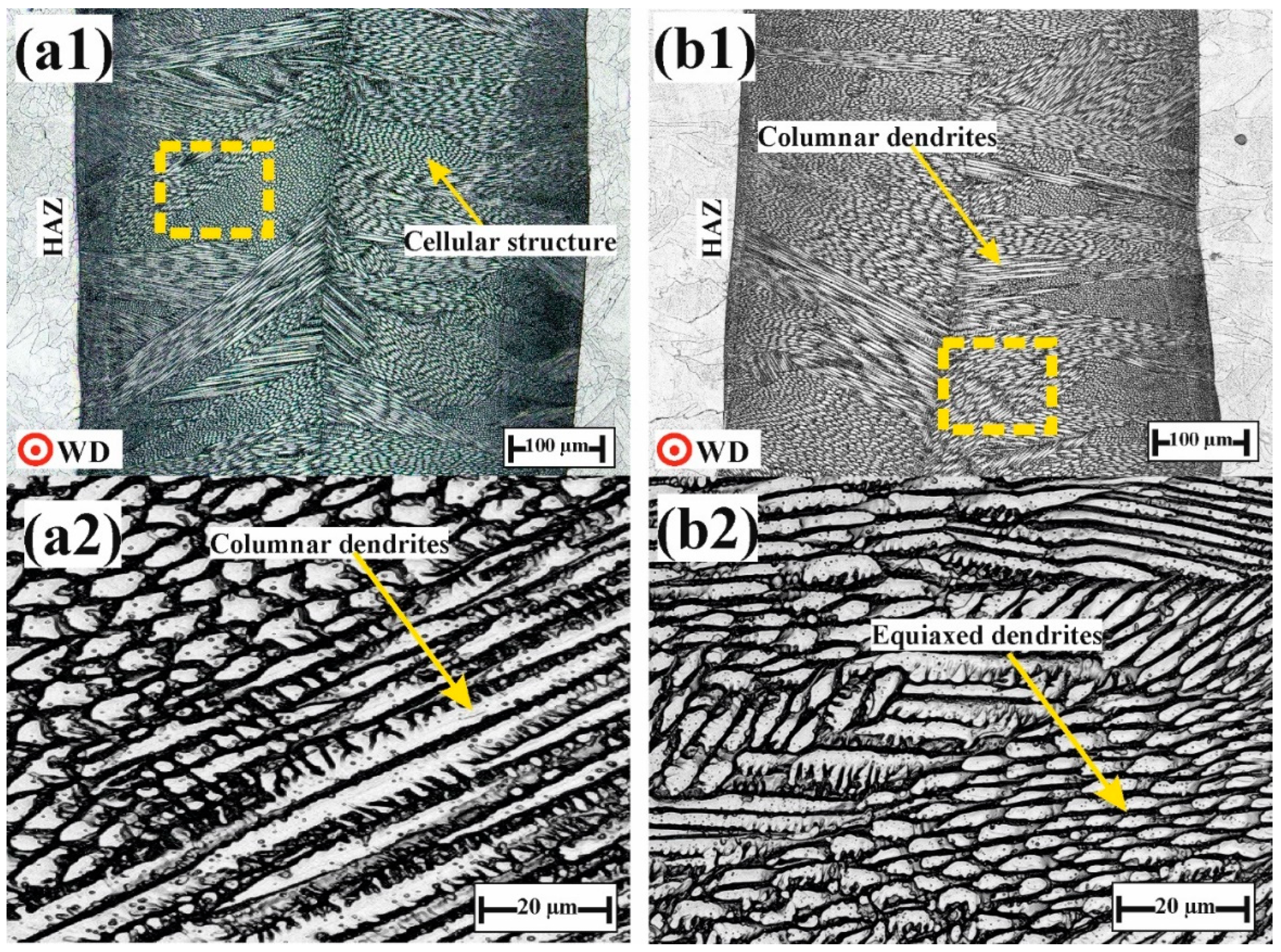
- The building orientation significantly impacts the grain morphology of the base metal, affecting both grain size and orientation. For example, columnar grains tend to align with the build direction, forming perpendicularly to the fusion path.
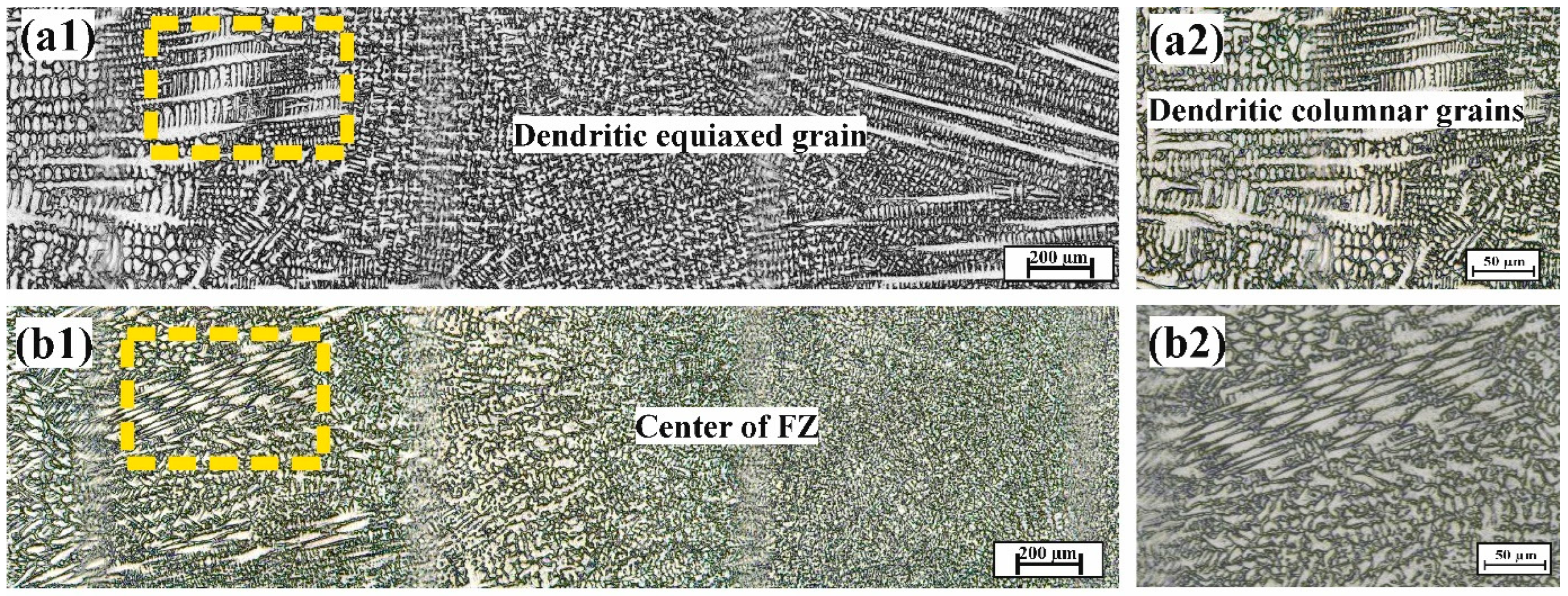
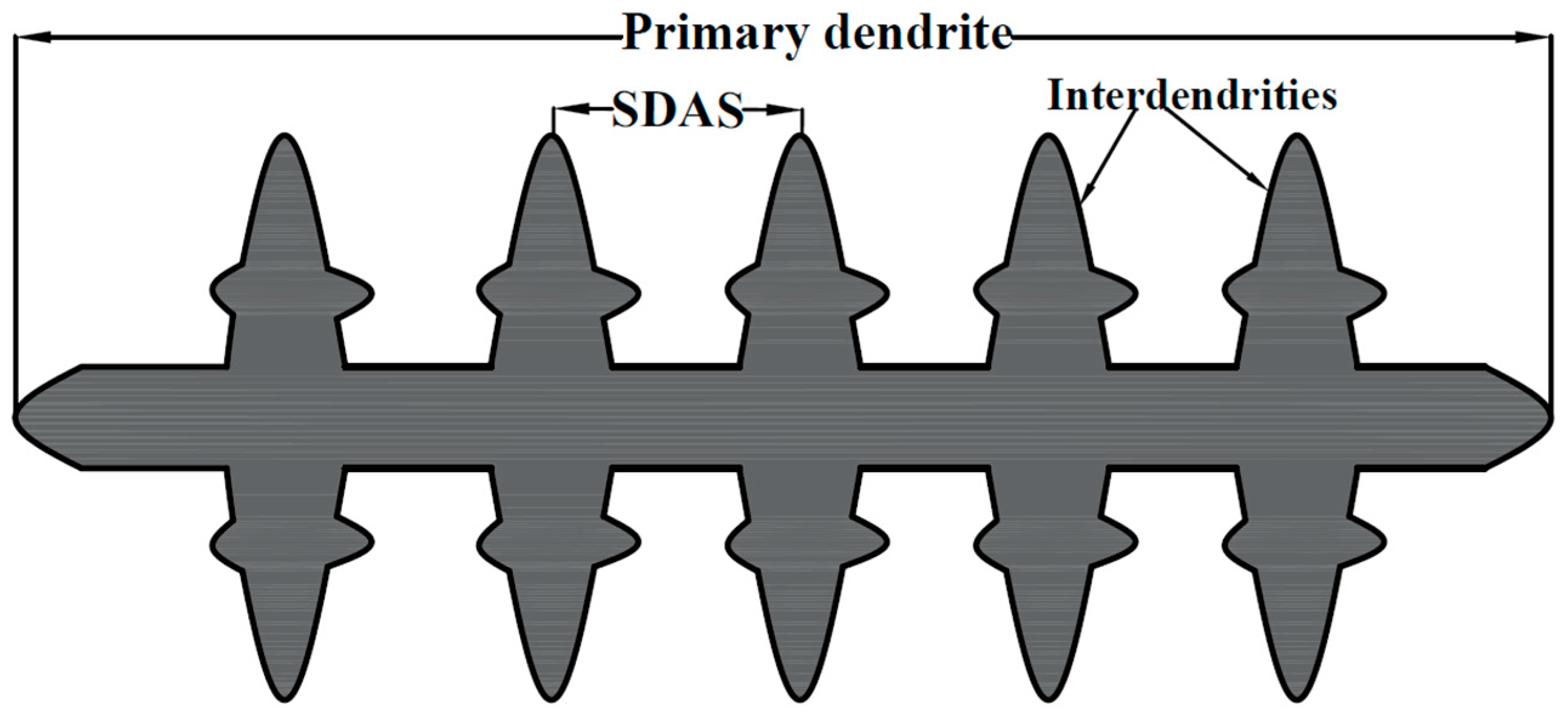
- The dimensions of dendrite arms and grain size in the FZ of TIG-welded joints are influenced by the building orientation of the BMs. When the welding direction is parallel to the built layer, as observed in BO-90 specimens, the FZ shows finer interdendritic spacing and a smaller grain size compared to those welded perpendicularly to the built layers, as observed in BO-0. Specifically, the finest dendritic arm spacing (SDAS) was noticed in BO-90 welded joints, with an average value of 5 ± 0.5 µm, whereas this was recorded as 8 ± 0.5 µm in BO-0 joints.
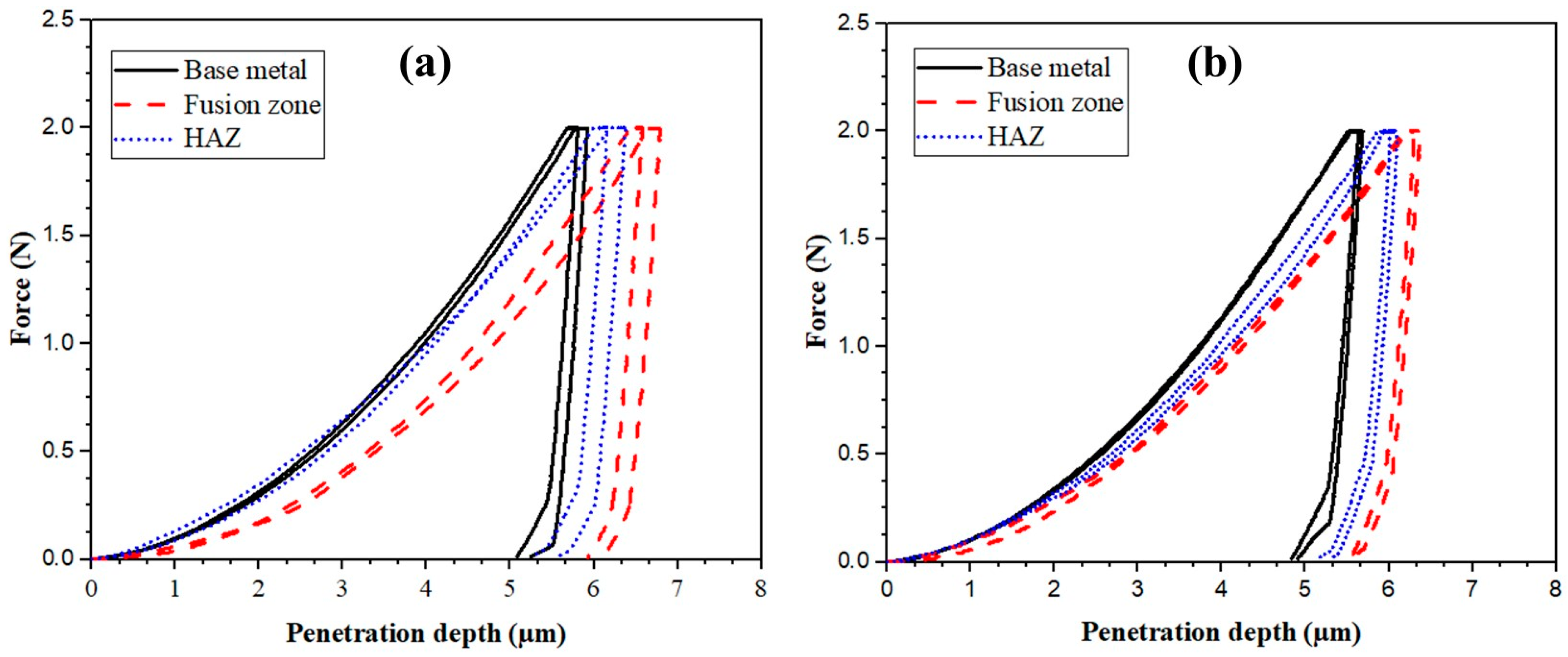
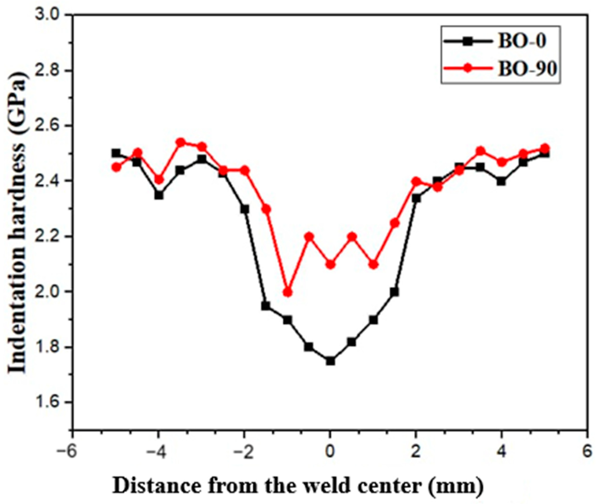
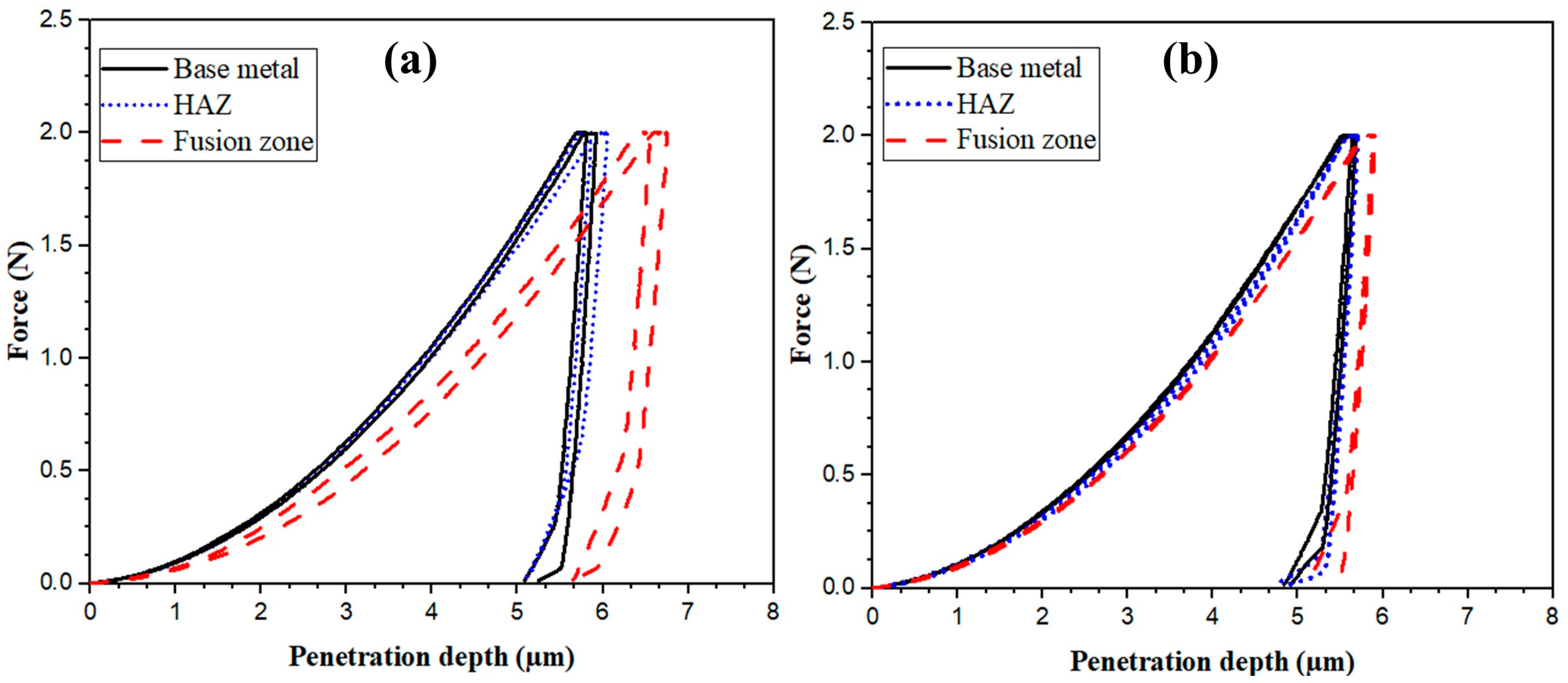
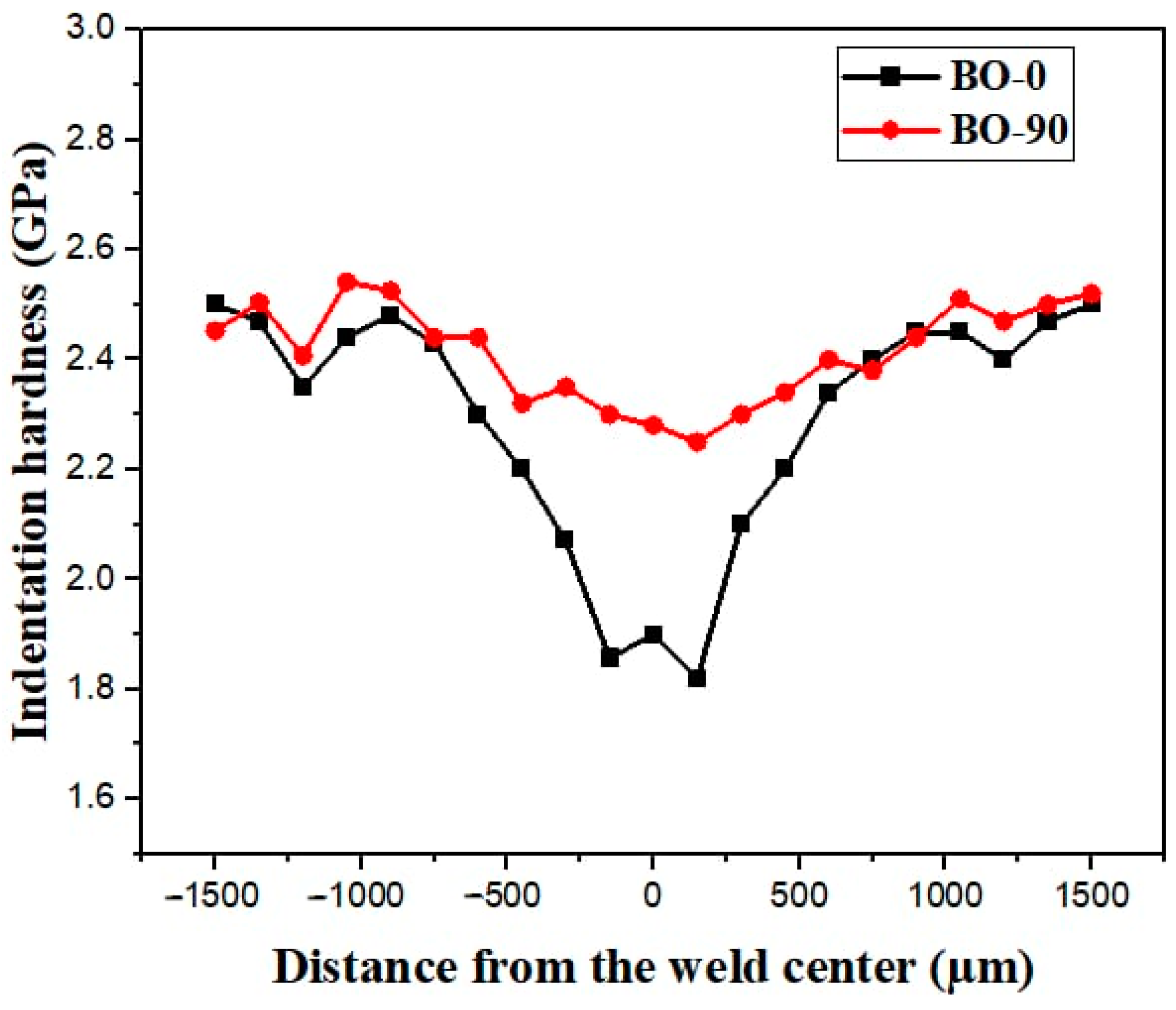
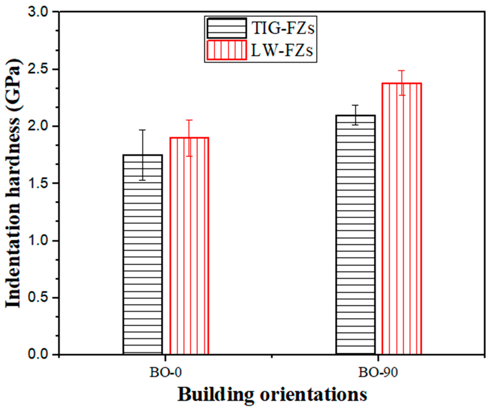
- In both welding techniques, the indentation hardness values within the fusion zones varied depending on the welding direction relative to the build direction. BO-0 joints exhibited lower indentation hardness compared to BO-90 joints. This is likely attributed to the higher cooling rate experienced by BO-90 joints during the welding process compared to BO-0 joints.
- The higher cooling rate following the welding process results in finer structures within the fusion zone (FZ), directly influencing the indentation hardness values of the welded joints. Specifically, the FZ of the BO-90 orientation exhibited higher hardness, measuring 2.1 ± 0.09 GPa and 2.35 ± 0.11 GPa in TIG and laser welding, respectively. These values surpass the hardness of the FZ in BO-0 joints, which was recorded as 1.75 ± 0.18 GPa and 1.9 ± 0.16 GPa in TIG and laser welding, respectively.
- The similarity of laser beam characteristics between the printing process and laser welding technique offers the advantage of producing welded joints with a unified microstructure. This approach results in a finer microstructure, which in turn leads to increased indentation hardness in laser-welded joints compared to those produced by TIG welding.
Author Contributions
Funding
Institutional Review Board Statement
Informed Consent Statement
Data Availability Statement
Conflicts of Interest
References
- Abraham, G.; Shaikh, H. Introduction to Austenitic Stainless Steels. In Corrosion of Austenitic Stainless Steels; Woodhead Publishing: Cambridge, UK, 2002. [Google Scholar] [CrossRef]
- Saravanan, M.; Devaraju, A.; Venkateshwaran, N.; Krishnakumari, A.; Saarvesh, J. A review on recent progress in coatings on AISI austenitic stainless steel. Mater. Today Proc. 2018, 5, 14392–14396. [Google Scholar] [CrossRef]
- Li, S.-X.; He, Y.-N.; Yu, S.-R.; Zhang, P.-Y. Evaluation of the effect of grain size on chromium carbide precipitation and intergranular corrosion of 316L stainless steel. Corros. Sci. 2013, 66, 211–216. [Google Scholar] [CrossRef]
- Klyushina, A.; Pacultová, K.; Krejčová, S.; Słowik, G.; Jirátová, K.; Kovanda, F.; Ryczkowski, J.; Obalová, L. Advantages of stainless steel sieves as support for catalytic N2O decomposition over K-doped Co3O4. Catal. Today 2015, 257, 2–10. [Google Scholar] [CrossRef]
- Liu, M.; Kumar, A.; Bukkapatnam, S.; Kuttolamadom, M. A Review of the Anomalies in Directed Energy Deposition (DED) Processes & Potential Solutions—Part Quality & Defects. Procedia Manuf. 2021, 53, 507–518. [Google Scholar] [CrossRef]
- Diegel, O.; Nordin, A.; Motte, D. Additive Manufacturing Technologies. In A Practical Guide to Design for Additive Manufacturing; Springer Series in Advanced Manufacturing; Springer: Singapore, 2019; pp. 19–39. [Google Scholar] [CrossRef]
- Gong, G.; Ye, J.; Chi, Y.; Zhao, Z.; Wang, Z.; Xia, G.; Du, X.; Tian, H.; Yu, H.; Chen, C. Research status of laser additive manufacturing for metal: A review. J. Mater. Res. Technol. 2021, 15, 855–884. [Google Scholar] [CrossRef]
- Khedr, M.; Elshokrofy, H.; Pokka, A.-P.; Hamada, A.; Jaskari, M.; Mustakangas, A.; Järvenpää, A.; Ibrahim, A.; Elsamanty, M. Effect of design parameters on auxetic behavior and stiffness of additively manufactured 316L stainless steel. J. Mater. Res. Technol. 2024, 30, 8805–8814. [Google Scholar] [CrossRef]
- Paraschiv, A.; Matache, G.; Condruz, M.R.; Frigioescu, T.F.; Pambaguian, L. Laser Powder Bed Fusion Process Parameters’ Optimization for Fabrication of Dense IN 625. Materials 2022, 15, 5777. [Google Scholar] [CrossRef]
- Huysmans, S.; Peeters, E.; De Bruycker, E.; De Prins, K. Weldability study of additive manufactured 316L austenitic stainless steel components—Welding of AM with conventional 316L components. Weld. World 2021, 65, 1415–1427. [Google Scholar] [CrossRef]
- Mohyla, P.; Hajnys, J.; Sternadelová, K.; Krejčí, L.; Pagáč, M.; Konečná, K.; Krpec, P. Analysis of welded joint properties on an AISI316L stainless steel tube manufactured by SLM technology. Materials 2020, 13, 4362. [Google Scholar] [CrossRef]
- Khedr, M.; Elsayed, M.; Jaskari, M.; Abdel-Aleem, H.A.; Gaafer, A.M.; Hamada, A. Effect of building orientation on weld characteristics of additively manufactured 316L stainless steel: Microstructure and mechanical properties. Mater. Sci. Eng. A 2024, 913, 147086. [Google Scholar] [CrossRef]
- Rappaz, M.; David, S.A.; Vitek, J.M.; Boatner, L.A. Analysis of solidification microstructures in Fe-Ni-Cr single-crystal welds. Metall. Trans. A 1990, 21, 1767–1782. [Google Scholar] [CrossRef]
- Feng, L.; Gao, J.; Liu, F.; Liu, F.; Huang, C.; Zheng, Y. Effect of grain orientation on microstructure and mechanical properties of laser welded joint of additive manufactured 300M steel. Mater. Today Commun. 2023, 35, 105497. [Google Scholar] [CrossRef]
- Kou, S. Welding Metallurgy, 3rd ed.; Wiley: Hoboken, NJ, USA, 2021. [Google Scholar]
- Casalino, G.; Campanelli, S.L.; Ludovico, A.D. Laser-arc hybrid welding of wrought to selective laser molten stainless steel. Int. J. Adv. Manuf. Technol. 2013, 68, 209–216. [Google Scholar] [CrossRef]
- Chen, N.; Ma, G.; Zhu, W.; Godfrey, A.; Shen, Z.; Wu, G.; Huang, X. Enhancement of an additive-manufactured austenitic stainless steel by post-manufacture heat-treatment. Mater. Sci. Eng. A 2019, 759, 65–69. [Google Scholar] [CrossRef]
- Lee, S.; Ghiaasiaan, R.; Shao, S.; Gradl, P.; Shamsaei, N. Additively Manufactured 316L Stainless Steel: Effect of Heat Treatment on Microstructure and Tensile Properties. In Proceedings of the 2022 International Solid Freeform Fabrication Symposium, Austin, TX, USA, 25–27 July 2022. [Google Scholar]
- Jaskari, M.; Mäkikangas, J.; Järvenpää, A.; Mäntyjärvi, K.; Karjalainen, P. Effect of high porosity on bending fatigue properties of 3D printed AISI 316L steel. Procedia Manuf. 2019, 36, 33–41. [Google Scholar] [CrossRef]
- Mäkikangas, J.; Rautio, T.; Jalava-Kanervio, J.; Mustakangas, A.; Järvenpää, A. Laser Welding of Laser Powder Bed Fusion (LPBF) Manufactured 316L Stainless Steel Lap Joint. Key Eng. Mater. 2021, 883, 242–249. [Google Scholar] [CrossRef]
- Rautio, T.; Hamada, A.; Kumpula, J.; Järvenpää, A.; Allam, T. Enhancement of electrical conductivity and corrosion resistance by silver shell-copper core coating of additively manufactured AlSi10Mg alloy. Surf. Coat. Technol. 2020, 403, 126426. [Google Scholar] [CrossRef]
- Chadha, K.; Tian, Y.; Spray, J.G.; Aranas, C. Effect of annealing heat treatment on the microstructural evolution and mechanical properties of hot isostatic pressed 316L stainless steel fabricated by laser powder bed fusion. Metals 2020, 10, 753. [Google Scholar] [CrossRef]
- Sohrabpoor, H.; Salarvand, V.; Lupoi, R.; Chu, Q.; Li, W.; Aldwell, B.; Stanley, W.; O’Halloran, S.; Raghavendra, R.; Choi, C.H.; et al. Microstructural and mechanical evaluation of post-processed SS 316L manufactured by laser-based powder bed fusion. J. Mater. Res. Technol. 2021, 12, 210–220. [Google Scholar] [CrossRef]
- Khedr, M.; Awad, I.; Jaskari, M.; Ali, M.; Abdel-Aleem, H.; Mahmoud, T.; Hamada, A. Microstructural Evolution and Mechanical Performance of Two Joints of Medium-Mn Stainless Steel with Low-and High-Alloyed Steels. Materials 2023, 16, 1624. [Google Scholar] [CrossRef]
- Awad, I.; Khedr, M.; Mahmoud, T.; Abdel-Aleem, H.; Hamada, A. Study on the Mechanical Performance of Dissimilar Butt Joints between Low Ni Medium-Mn and Ni-Cr Austenitic Stainless Steels Processed by Gas Tungsten Arc Welding. Met.-Open Access Metall. J. 2021, 11, 1439. [Google Scholar] [CrossRef]
- EN 1011-3:2018; Welding—Recommendations for Welding of Metallic Materials—Part 3: Arc Welding of Stainless Steels. European Committee for Standardization: Brussels, Belgium, 2018. [CrossRef]
- Weman, K. Introduction to welding. In Welding Processes Handbook, 2nd, ed.; Elsevier: Amsterdam, The Netherlands, 2012; pp. 1–12. [Google Scholar]
- ISO 8249:2018; Welding. Determination of Ferrite Number (FN) in Austenitic and duplex Ferritic-Austenitic Cr-Ni stainless Steel Weld Metals. IOS: Geneva, Switzerland, 2018. [CrossRef]
- Schaeffler, A.L. Constitution diagram for stainless steel weld metal. Met. Prog. 1949, 56, 680. [Google Scholar]
- Matilainen, V.P.; Pekkarinen, J.; Salminen, A. Weldability of additive manufactured stainless steel. Phys. Procedia 2016, 83, 808–817. [Google Scholar] [CrossRef]
- Köse, C. Fiber laser beam welding of additive manufactured 316L austenitic stainless steel with wrought 2507 super duplex and wrought 904L super austenitic stainless steels: Crystallographic texture, microstructure, and mechanical properties. Vacuum 2023, 215, 112347. [Google Scholar] [CrossRef]
- Mokhtari, M.; Pommier, P.; Balcaen, Y.; Alexis, J. Laser Welding of AISI 316L Stainless Steel Produced by Additive Manufacturing or by Conventional Processes. J. Manuf. Mater. Process. 2021, 5, 136. [Google Scholar] [CrossRef]
- Kumar, M.P.; Varahamoorthi, R.; Gnanamurugan, K. Materials Today: Proceedings Modelling and optimization of process parameters to obtain maximum tensile strength for laser butt welding of 316L austenitic stainless steel sheets. Mater. Today Proc. 2020, 26, 1380–1388. [Google Scholar] [CrossRef]
- ASTM E407-07; Standard Practice for Microetching Metals and Alloys. ASTM Int.: West Conshohocken, PA, USA, 2007.
- Kang, L.; Chen, F.; Bradford, M.A.; Liu, X. Experimental study of mechanical properties of laser additively manufactured 316L stainless steels. Structures 2023, 54, 221–235. [Google Scholar] [CrossRef]
- Cai, W.; Song, Q.; Ji, H.; Gupta, M.K. Multi-Perspective Analysis of Building Orientation Effects on Microstructure, Mechanical and Surface Properties of SLM Ti6Al4V with Specific Geometry. Materials 2021, 14, 4392. [Google Scholar] [CrossRef]
- Xie, Z.; Dai, Y.; Ou, X.; Ni, S.; Song, M. Effects of selective laser melting build orientations on the microstructure and tensile performance of Ti–6Al–4V alloy. Mater. Sci. Eng. A 2020, 776, 139001. [Google Scholar] [CrossRef]
- Choo, H.; Sham, K.-L.; Bohling, J.; Ngo, A.; Xiao, X.; Ren, Y.; Depond, P.J.; Matthews, M.J.; Garlea, E. Effect of laser power on defect, texture, and microstructure of a laser powder bed fusion processed 316L stainless steel. Mater. Des. 2019, 164, 107534. [Google Scholar] [CrossRef]
- Kou, S. Nucleation and Growth of Grains. In Welding Metallurgy, 3rd ed.; Wiley: Hoboken, NJ, USA, 2020. [Google Scholar]
- van Putten, K.; Kopp, R.; Hirt, G. Size effects in the production of micro strip by the flat rolling of wire. In 4M 2006-Second International Conference on Multi-Material Micro Manufacture; Menz, W., Dimov, S., Fillon, B., Eds.; Elsevier: Oxford, UK, 2006; pp. 277–280. [Google Scholar] [CrossRef]
- Moi, S.; Pal, P.K.; Rudrapati, R. Effect of Heat Input on the Mechanical and Metallurgical Characteristics of TIG Welded Joints. J. Mech. Eng. (JMechE) 2019, 16, 29–40. [Google Scholar] [CrossRef]
- Vanovsek, W.; Bernhard, C.; Fiedler, M.; Posch, G. Influence of aluminum content on the characterization of microstructure and inclusions in high-strength steel welds. Weld. World 2013, 57, 73–83. [Google Scholar] [CrossRef]
- Schönmaier, H.; Krein, R.; Schmitz-Niederau, M.; Schnitzer, R. Influence of the Heat Input on the Dendritic Solidification Structure and the Mechanical Properties of 2.25Cr-1Mo-0.25V Submerged-Arc Weld Metal. J. Mater. Eng. Perform. 2021, 30, 7138–7151. [Google Scholar] [CrossRef]
- Elmer, J.; Allen, S.; Eagar, T. The influence of cooling rate on the ferrite content of stainless steel alloys. Recent Trends Weld. Sci. Technol. 1990, 165–170. [Google Scholar]
- Guo, W.; Dong, S.; Guo, W.; Francis, J.A.; Li, L. Microstructure and mechanical characteristics of a laser welded joint in SA508 nuclear pressure vessel steel. Mater. Sci. Eng. A 2015, 625, 65–80. [Google Scholar] [CrossRef]
- Dinda, G.P.; Dasgupta, A.K.; Mazumder, J. Evolution of microstructure in laser deposited Al–11.28%Si alloy. Surf. Coatings Technol. 2012, 206, 2152–2160. [Google Scholar] [CrossRef]
- Dinda, G.P.; Dasgupta, A.K.; Mazumder, J. Texture control during laser deposition of nickel-based superalloy. Scr. Mater. 2012, 67, 503–506. [Google Scholar] [CrossRef]
- Kim, B.; Uhm, S.; Lee, C.; Lee, J.; An, Y. Effects of Inclusions and Microstructures on Impact Energy of High Heat-Input Submerged-Arc-Weld Metals. J. Eng. Mater. Technol. 2005, 127, 204–213. [Google Scholar] [CrossRef]
- Prasad, K.; Dwivedi, D.K. Some investigations on microstructure and mechanical properties of submerged arc welded HSLA steel joints. Int. J. Adv. Manuf. Technol. 2008, 36, 475–483. [Google Scholar] [CrossRef]
- Prasad, K.; Dwivedi, D.K. Microstructure and Tensile Properties of Submerged Arc Welded 1.25Cr-0.5Mo Steel Joints. Mater. Manuf. Process. 2008, 23, 463–468. [Google Scholar] [CrossRef]
- Wenkai, X.; Li, Z.; Fuju, Z.; Kesun, D.; Xian, Z.; Xue, Y.; Bingjun, C. Effect of heat input on cryogenic toughness of 316LN austenitic stainless steel NG-MAG welding joints with large thickness. JMADE 2015, 86, 160–167. [Google Scholar] [CrossRef]
- Kumar, S.; Shahi, A.S. Effect of heat input on the microstructure and mechanical properties of gas tungsten arc welded AISI 304 stainless steel joints. Mater. Des. 2011, 32, 3617–3623. [Google Scholar] [CrossRef]
- Vilaro, T.; Colin, C.; Bartout, J.D.; Nazé, L.; Sennour, M. Microstructural and mechanical approaches of the selective laser melting process applied to a nickel-base superalloy. Mater. Sci. Eng. A 2012, 534, 446–451. [Google Scholar] [CrossRef]
- Zheng, L.; Liu, Y.; Sun, S.; Zhang, H. Selective laser melting of Al–8.5Fe–1.3V–1.7Si alloy: Investigation on the resultant microstructure and hardness. Chin. J. Aeronaut. 2015, 28, 564–569. [Google Scholar] [CrossRef]
- Zhang, C.; Bao, Y.; Zhu, H.; Xiaojia, N.; Zhang, W.; Zhang, S.; Zeng, X. A comparison between laser and TIG welding of selective laser melted AlSi10Mg. Opt. Laser Technol. 2019, 120, 105696. [Google Scholar] [CrossRef]


| Element | Cr | Ni | Mo | Si | Mn | C | Nb | Ti | N | Fe |
|---|---|---|---|---|---|---|---|---|---|---|
| wt.% | 17.70 | 12.90 | 2.50 | 0.70 | 0.6 | 0.02 | 0.005 | 0.01 | 0.09 | Bal. |
| Element | Cr | Ni | Mo | Si | Mn | C | P | S | Cu | Fe |
|---|---|---|---|---|---|---|---|---|---|---|
| wt.% | 18.0 | 12.50 | 2.60 | 0.40 | 1.51 | 0.01 | 0.02 | 0.01 | 0.1 | Bal. |
| Current in Ampere (A) | Voltage (V) | Welding Length (mm) | Welding Time (s) | Travel Speed (mm/s) | Heat Input (kJ/mm) |
|---|---|---|---|---|---|
| 100 | 12 | 60 | 30 | 2 | 0.36 |
| Laser Power (Watt) | Optical Diameter (µm) | Focal Point Level (mm) | Welding Speed (mm/s) | Energy Input (J/mm) |
|---|---|---|---|---|
| 3000 | 200 | −1 | 60 | 50 |
| Condition | Width of Fusion Zone (mm) | Width of Equiaxed Grain Region (mm) | Analysis of Fusion Zones | ||
|---|---|---|---|---|---|
| Average Grain Size (µm) | Average Dendrite Length (µm) | SDAS (µm) | |||
| BO-0 | 6.8 ± 0.5 | 1.1 | 8 ± 0.5 | 178 ± 4 | 10 ± 1 |
| BO-90 | 4.6 ± 0.5 | 2.6 | 5 ± 0.5 | 42 ± 4 | 6 ± 1 |
| Condition | Cr | Ni | Mo | C | Mn | Nb | Ti | Si | Creq | Nieq |
|---|---|---|---|---|---|---|---|---|---|---|
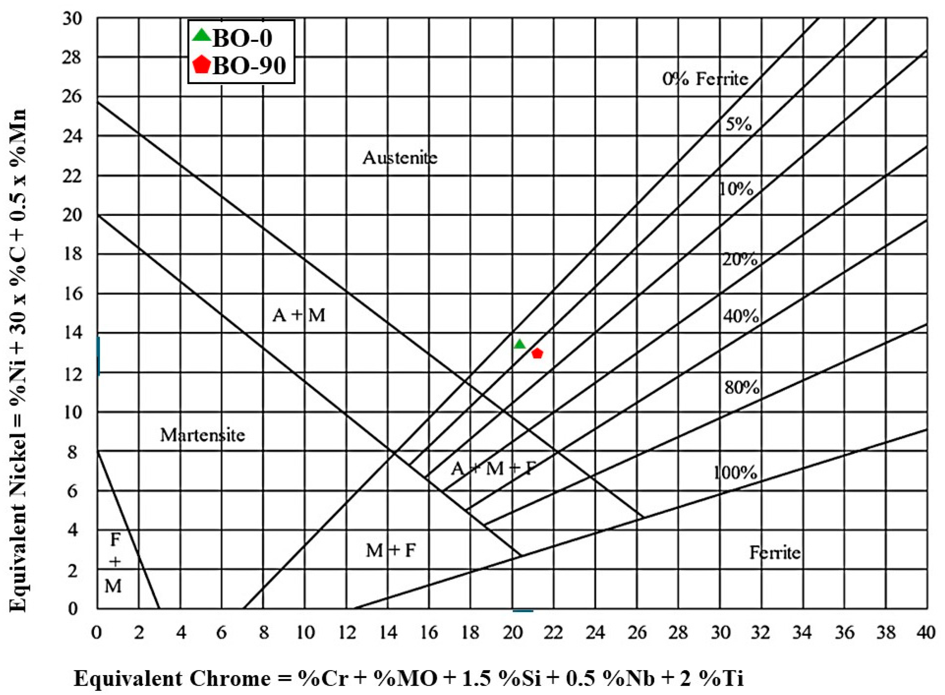
| BO-0 | 17.0 | 12.2 | 2.35 | 0.0143 | 1.32 | 0.088 | 0.0108 | 0.601 | 20.32 | 13.42 |
| BO-90 | 17.8 | 11.8 | 2.33 | 0.0174 | 1.19 | 0.0927 | 0.0229 | 0.635 | 20.96 | 13.14 |
| BO-0 | BO-90 | |||||
|---|---|---|---|---|---|---|
| BM | FZ | HAZ | BM | FZ | HAZ | |
| HIT (GPa) | 2.43 ± 0.17 | 1.75 ± 0.22 | 1.95 ± 0.22 | 2.45 ± 0.15 | 2.1 ± 0.09 | 2.2 ± 0.19 |
| PD (µm) | 5.69 ± 0.2 | 6.7 ± 0.2 | 6 ± 0.2 | 5.61 ± 0.13 | 6.1 ± 0.15 | 5.82 ± 0.12 |
| BO-0 | BO-90 | |||||
|---|---|---|---|---|---|---|
| BM | FZ | HAZ | BM | FZ | HAZ | |
| HIT (GPa) | 2.43 ± 0.15 | 1.9 ± 0.16 | 2.28 ± 0.08 | 2.45 ± 0.08 | 2.35 ± 0.11 | 2.42 ± 0.1 |
| PD (µm) | 5.75 ± 0.2 | 6.6 ± 0.16 | 5.85 ± 0.17 | 5.70 ± 0.13 | 5.88 ± 0.16 | 5.77 ± 0.17 |
Disclaimer/Publisher’s Note: The statements, opinions and data contained in all publications are solely those of the individual author(s) and contributor(s) and not of MDPI and/or the editor(s). MDPI and/or the editor(s) disclaim responsibility for any injury to people or property resulting from any ideas, methods, instructions or products referred to in the content. |
© 2024 by the authors. Licensee MDPI, Basel, Switzerland. This article is an open access article distributed under the terms and conditions of the Creative Commons Attribution (CC BY) license (https://creativecommons.org/licenses/by/4.0/).
Share and Cite
Elsayed, M.; Khedr, M.; Järvenpää, A.; Gaafer, A.M.; Hamada, A. Microstructure and Hardness Properties of Additively Manufactured AISI 316L Welded by Tungsten Inert Gas and Laser Welding Techniques. Materials 2024, 17, 4489. https://doi.org/10.3390/ma17184489
Elsayed M, Khedr M, Järvenpää A, Gaafer AM, Hamada A. Microstructure and Hardness Properties of Additively Manufactured AISI 316L Welded by Tungsten Inert Gas and Laser Welding Techniques. Materials. 2024; 17(18):4489. https://doi.org/10.3390/ma17184489
Chicago/Turabian StyleElsayed, Mohamed, Mahmoud Khedr, Antti Järvenpää, A. M. Gaafer, and Atef Hamada. 2024. "Microstructure and Hardness Properties of Additively Manufactured AISI 316L Welded by Tungsten Inert Gas and Laser Welding Techniques" Materials 17, no. 18: 4489. https://doi.org/10.3390/ma17184489