
Study on the Compressive and Tensile Properties of Latex-Modified Cement Stone

Abstract
:1. Introduction
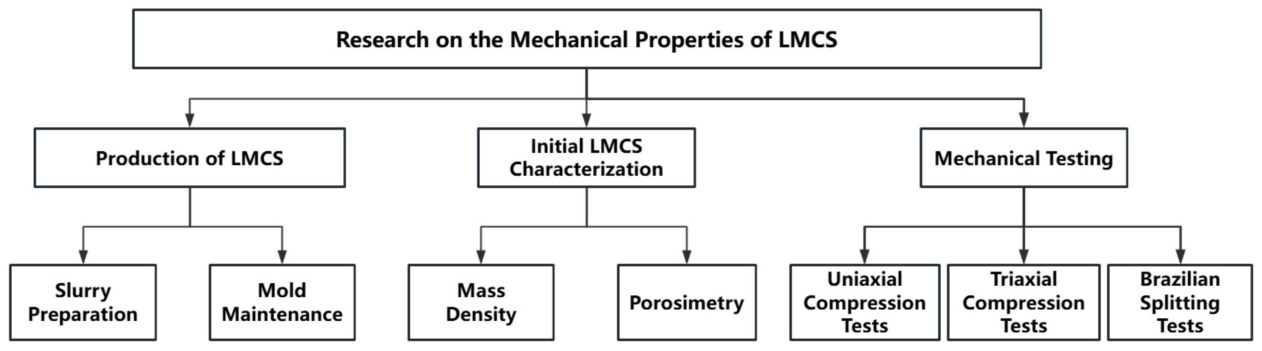
2. Experimental Materials and Procedures
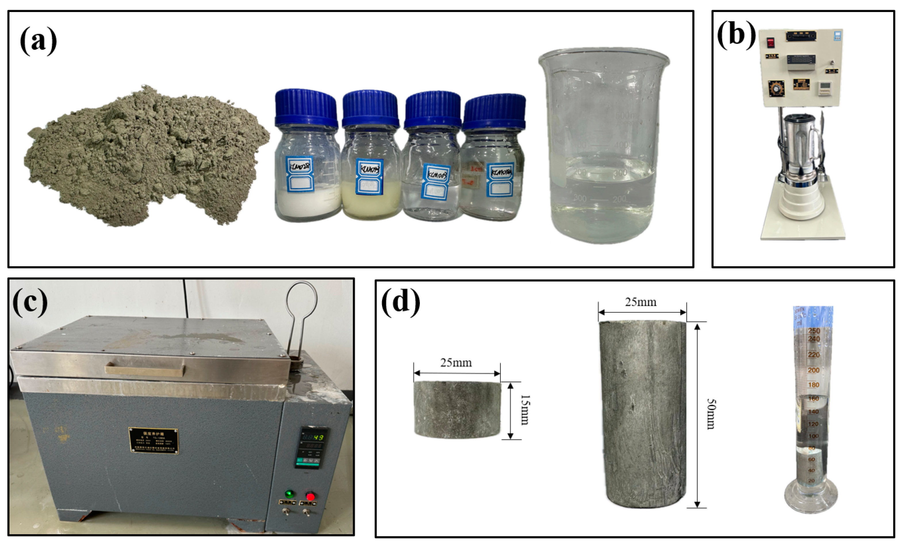
2.1. Sample Preparation
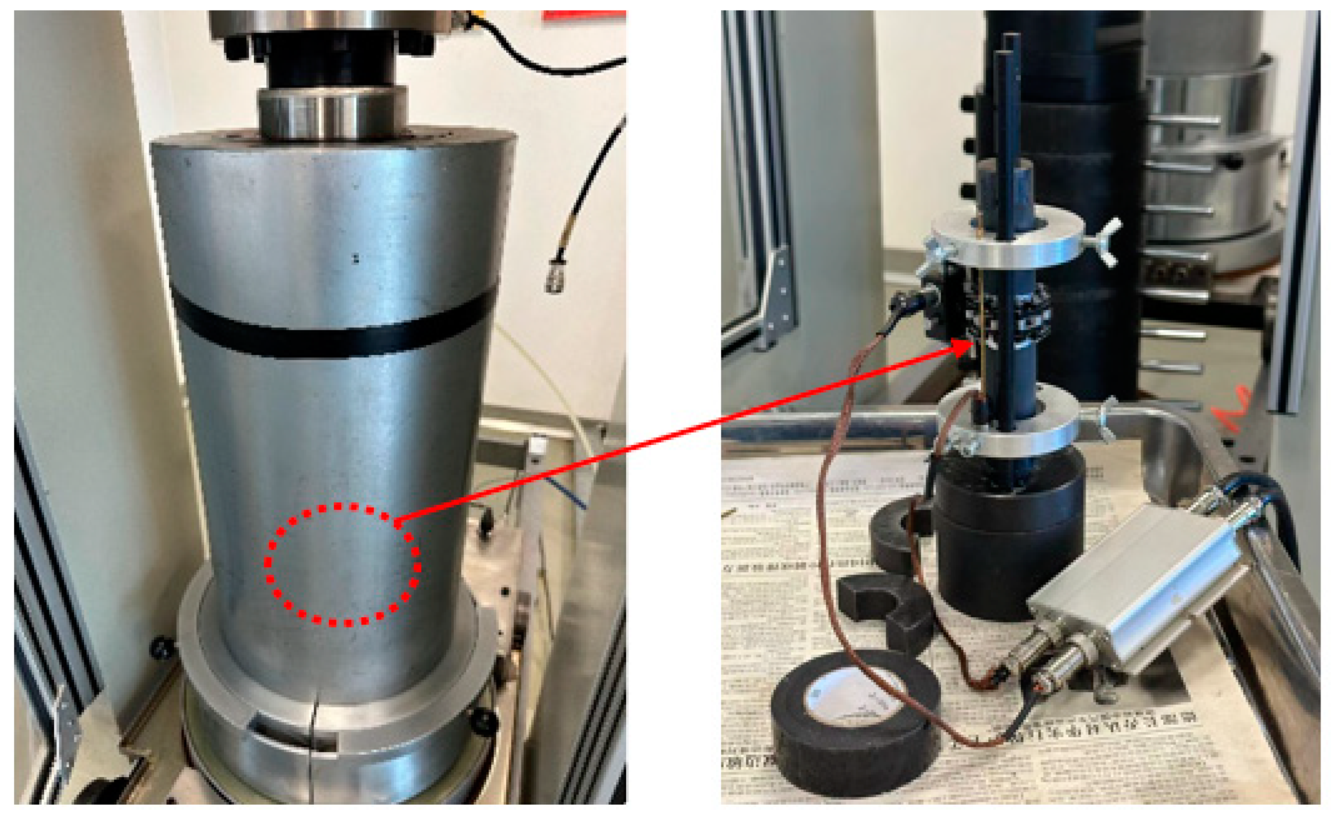
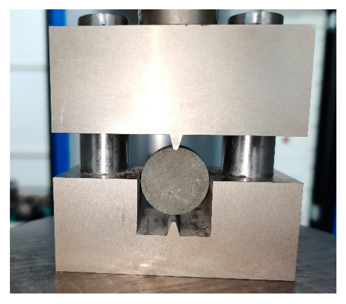
2.2. Experimental Procedure
3. Experimental Results and Discussion
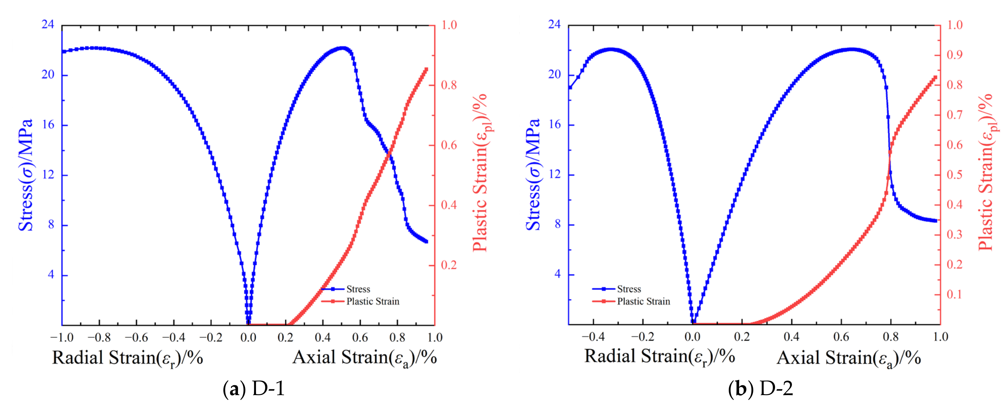
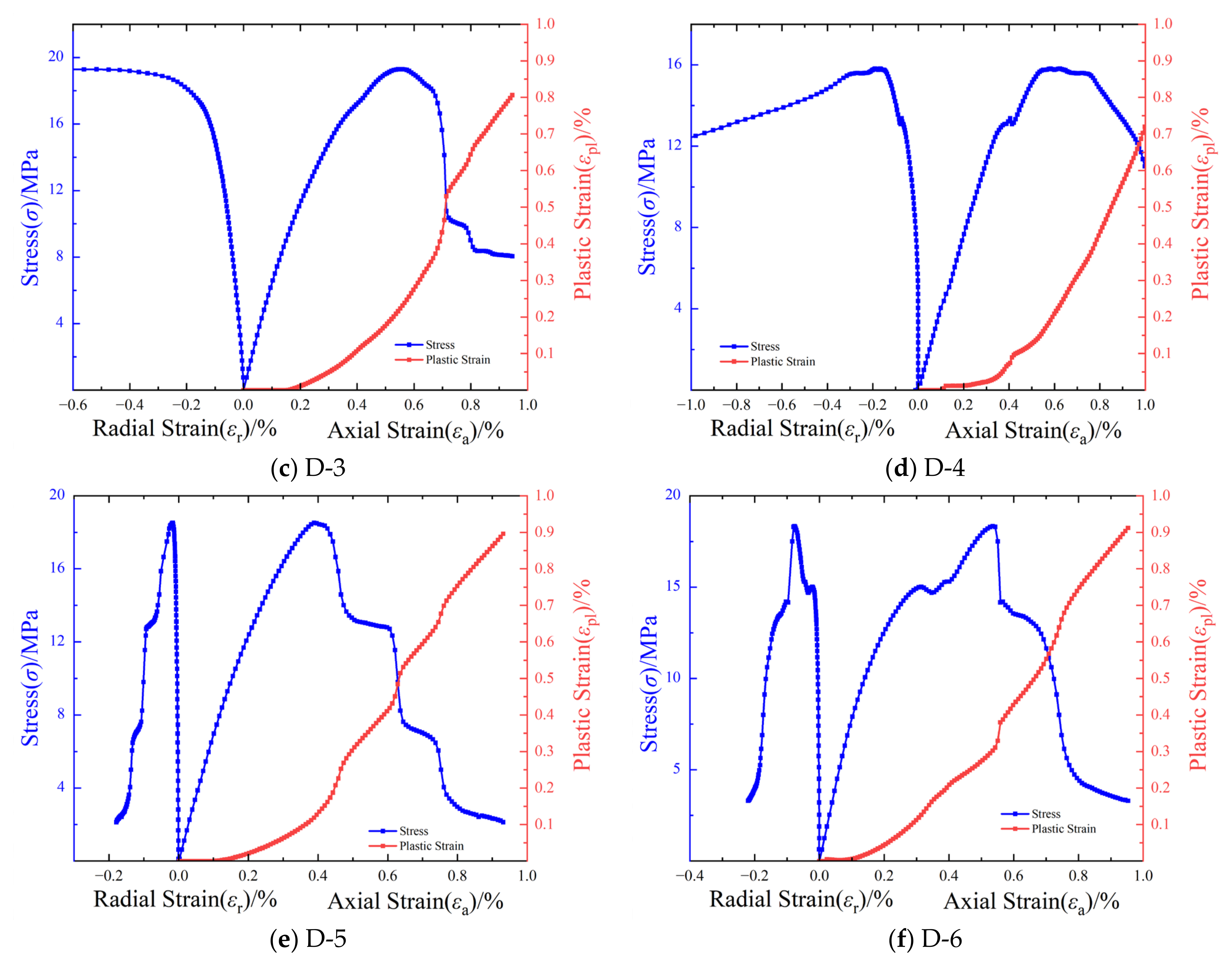
3.1. Study on Uniaxial Compression Properties
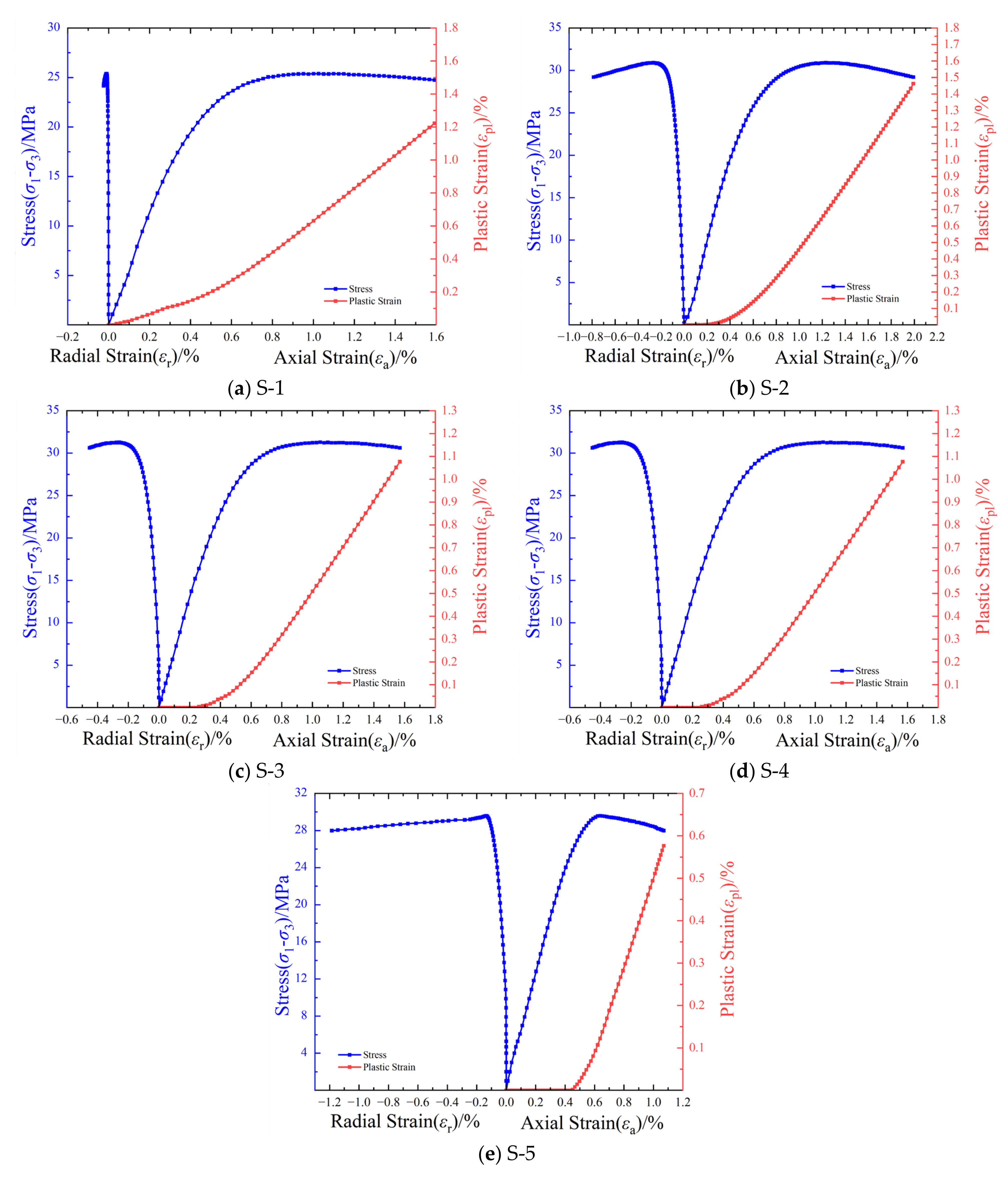
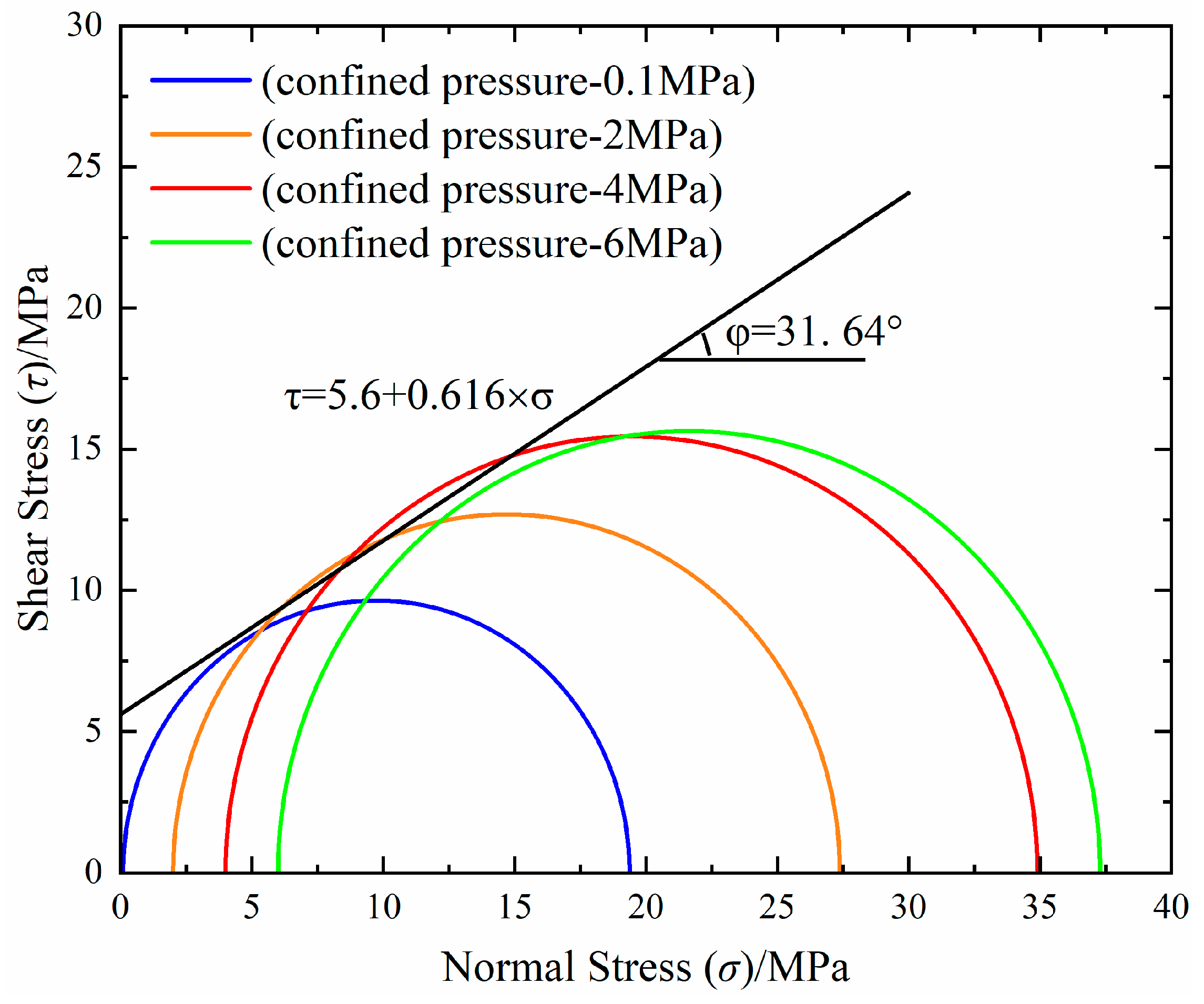
3.2. Study on Triaxial Compression Properties
3.3. Study on Tensile Properties
3.4. Discussion
4. Conclusions
- (1)
- Under uniaxial compression, LMCS exhibited an elastic compression modulus ranging from 4.08 to 8.29 GPa, a Poisson’s ratio of 0.05–0.46, and compressive strength ranging from 15.82 to 22.21 MPa. The compressive strength and elastic modulus of LMCS are relatively low compared to traditional cement or other modified cement used in oil and gas well construction. Under triaxial compression, these values were 4.48–6.87 GPa for the modulus, 0.05–0.16 for Poisson’s ratio, and 27.38–39.58 MPa for compressive strength. The tensile strength ranged from 2.34 to 3.72 MPa, with a corresponding tensile–compression ratio of approximately 0.15.
- (2)
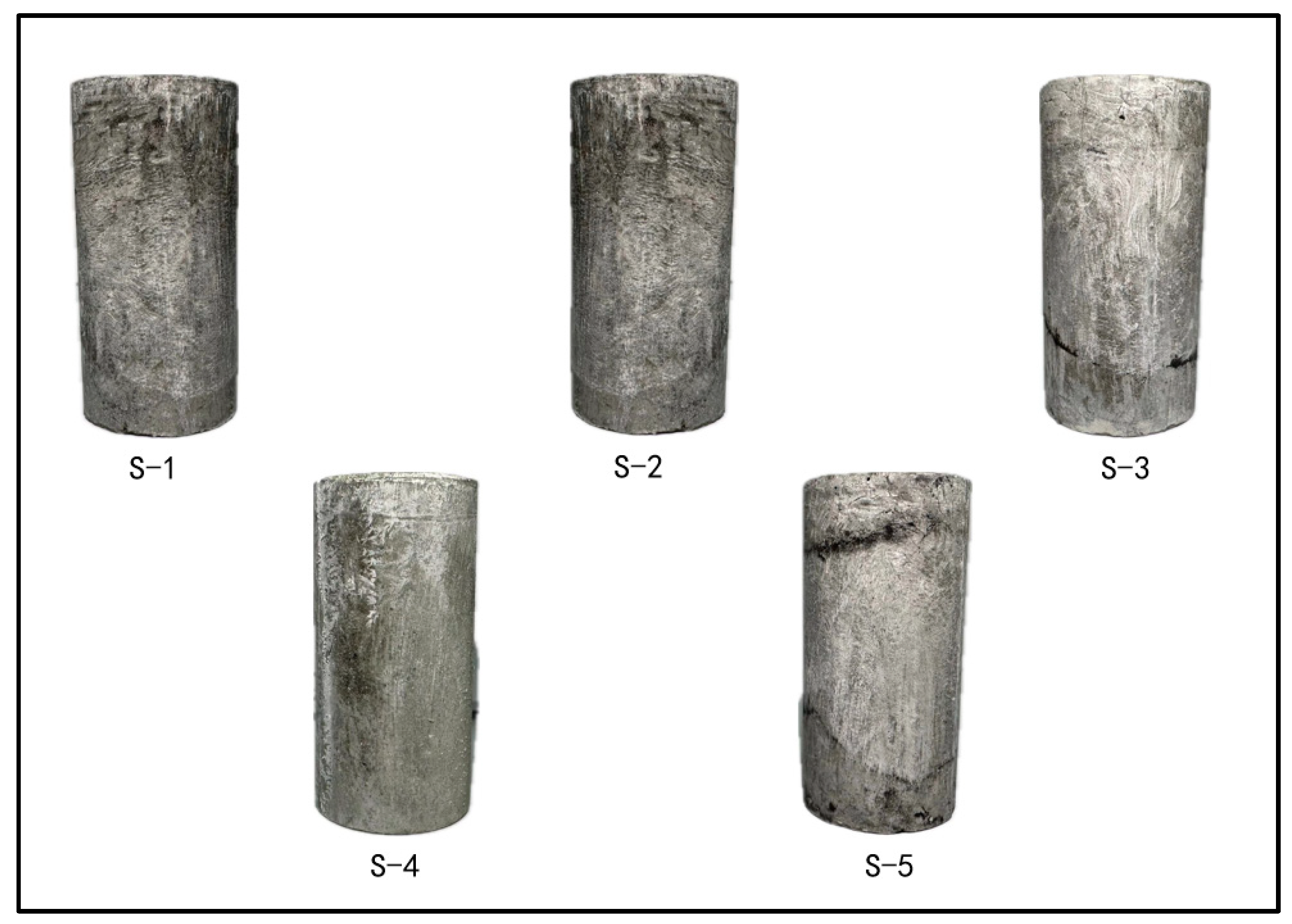
- After uniaxial compression failure, LMCS often exhibited cracks, occasionally forming a Y-shaped failure path. Conversely, under triaxial compression, the specimens did not produce macroscopic cracks.
- (3)
- The compressive strength of LMCS increased with the confining pressure. However, as the confining pressure continued to increase, the rate of increase in compressive strength gradually decreased.
- (4)
- A failure envelope of the form was generated. The strength criterion parameters calculated through triaxial compression tests can provide a reference for studying the constitutive relationship of LMCS and simulating triaxial compression.
- (5)
- All cement stone samples were cured in a controlled environment with a constant temperature of 50 °C. Further experiments are needed to discuss the variation in compressive strength with temperature and confining pressure in triaxial compression tests.
- (6)
- The experimental results of this article can provide necessary mechanical parameters for numerical calculation of failure analysis of oil and gas wellbore operation, thereby guiding the construction of oil and gas wells.
Author Contributions
Funding
Institutional Review Board Statement
Informed Consent Statement
Data Availability Statement
Conflicts of Interest
References
- Da Silva, A.C.; Miranda, H.B.; Andrade, H.M.; de Melo, S.A.V.; Gonçalves, J.P. Degradation of oil well cement with sodium chloride content exposed to supercritical carbon dioxide conditions: Temperature and pressure effects. J. Petrol. Sci. Eng. 2023, 220, 111198. [Google Scholar] [CrossRef]
- Patel, H.; Salehi, S. Structural integrity of liner cement in oil & gas wells: Parametric study, sensitivity analysis, and risk assessment. Eng. Fail. Anal. 2021, 122, 105203. [Google Scholar] [CrossRef]
- Wu, Z.; Chen, Z.; Liu, J.; Wang, C. An Investigation into PVA Fiber Modified with SiO2 for Improving Mechanical Properties of Oil-Well Cements. Materials 2024, 17, 2581. [Google Scholar] [CrossRef] [PubMed]
- Liu, S.; Sun, J.; Zhang, J.; Xie, Z.; Yu, Z. Effect of Graphene Oxide on the Mechanical Property and Microstructure of Clay-Cement Slurry. Materials 2023, 16, 4294. [Google Scholar] [CrossRef] [PubMed]
- Yang, H.; Bu, Y.; Guo, S.; Liu, H.; Du, J.; Cao, X. Effects of in-situ stress and elastic parameters of cement sheath in salt rock formation of underground gas storage on seal integrity of cement sheath. Eng. Fail. Anal. 2021, 123, 105258. [Google Scholar] [CrossRef]
- Zhou, S.; Liu, R.; Zeng, H.; Zeng, Y.; Zhang, L.; Zhang, J.; Li, X. Mechanical characteristics of well cement under cyclic loading and its influence on the integrity of shale gas wellbores. Fuel 2019, 250, 132–143. [Google Scholar] [CrossRef]
- Zhao, C.; Li, J.; Liu, G.; Zhang, X. Analysis of the influence of cement sheath failure on sustained casing pressure in shale gas wells. J. Nat. Gas Sci. Eng. 2019, 66, 244–254. [Google Scholar] [CrossRef]
- Bai, M. Risk assessment for CO2 leakage along abandoned wells using a monte carlo simulation in a CO2 sequestration site. Petrol Sci. Technol. 2014, 32, 1191–1200. [Google Scholar] [CrossRef]
- Wang, D.; Li, J.; Lian, W.; Yang, H.; Liu, X.; Liu, P.; Zhang, J. Simulation study on the evolution of cement plug sealing capability in CO2 geological sequestration wells. Geoenergy Sci. Eng. 2023, 227, 211944. [Google Scholar] [CrossRef]
- Sujak, A.; Pyzalski, M.; Durczak, K.; Brylewski, T.; Murzyn, P.; Pilarski, K. Studies on Cement Pastes Exposed to Water and Solutions of Biological Waste. Materials 2022, 15, 1931. [Google Scholar] [CrossRef]
- Durczak, K.; Pyzalski, M.; Brylewski, T.; Sujak, A. Effect of variable synthesis conditions on the formation of ye’elimite-aluminate-calcium (YAC) cement and its hydration in the presence of portland cement (OPC) and several accessory additives. Materials 2023, 16, 6052. [Google Scholar] [CrossRef] [PubMed]
- Abdalla, A.; Salih, A. Microstructure and chemical characterizations with soft computing models to evaluate the influence of calcium oxide and silicon dioxide in the fly ash and cement kiln dust on the compressive strength of cement mortar. Resour. Conserv. Recycl. Adv. 2022, 15, 200090. [Google Scholar] [CrossRef]
- Adjei, S.; Elkatatny, S. Overview of the lightweight oil-well cement mechanical properties for shallow wells. J. Petrol. Sci. Eng. 2021, 198, 108201. [Google Scholar] [CrossRef]
- Al-Luhybi, A.S.; Aziz, I.A.; Mohammad, K.I. Experimental assessment of mechanical and physical performance of latex modified concrete with fine recycled aggregate. Structures 2023, 48, 1932–1938. [Google Scholar] [CrossRef]
- Liu, H.; Bu, Y.; Zhou, A.; Du, J.; Zhou, L.; Pang, X. Silica sand enhanced cement mortar for cementing steam injection well up to 380 °C, Constr. Build. Mater. 2021, 308, 125142. [Google Scholar] [CrossRef]
- Jafariesfad, N.; Sangesland, S.; Gawel, K.; Torsæter, M. New materials and technologies for life-lasting cement sheath: A review of recent advances. SPE Drill. Complet. 2020, 35, 262–278. [Google Scholar] [CrossRef]
- Sugama, T.; Pyatina, T. Hydrophobic, Thermal Shock-and-Corrosion-Resistant XSBR Latex-Modified Lightweight Class G Cement Composites in Geothermal Well Energy Storage Systems. Materials 2023, 16, 5792. [Google Scholar] [CrossRef]
- Liu, J.; Wu, X.; Li, Z.; Song, W.; Liu, Y.; Shi, Q.; Chen, R. Mechanical properties and nonlinear deformation description model of cement stone. Geoenergy Sci. Eng. 2023, 223, 211578. [Google Scholar] [CrossRef]
- Su, D.; Li, Z.; Huang, S.; Wu, X.; Li, J.; Xue, Y. Experiment and failure mechanism of cement sheath integrity under development and production conditions based on a mechanical equivalent theory. Energy. Sci. Eng. 2021, 9, 2400–2422. [Google Scholar] [CrossRef]
- Mahmoud, A.A.; Elkatatny, S.; Ahmed, S.A.; Mahmoud, M. Nanoclay content influence on cement strength for oil wells subjected to cyclic steam injection and high-temperature conditions. In Proceedings of the Abu Dhabi International Petroleum Exhibition & Conference, Abu Dhabi, United Arab Emirates, 12–15 November 2018; p. 193059-MS. [Google Scholar] [CrossRef]
- Lima, V.N.; Skadsem, H.J.; Beltrán-Jiménez, K.; Zhemchuzhnikov, A.; Velloso, R.Q.; de Andrade Silva, F. Triaxial behavior of a stabilized and a highly porous oil well cement paste at different saturation and drainage conditions. J. Petrol. Sci. Eng. 2022, 219, 111055. [Google Scholar] [CrossRef]
- Quercia, G.; Chan, D.; Luke, K. Weibull statistics applied to tensile testing for oil well cement compositions. J. Petrol. Sci. Eng. 2016, 146, 536–544. [Google Scholar] [CrossRef]
- Zhang, H.; Šavija, B.; Schlangen, E. Combined experimental and numerical study on micro-cube indentation splitting test of cement paste. Eng. Fract. Mech. 2018, 199, 773–786. [Google Scholar] [CrossRef]
- Sun, H.; Li, F.; Shi, F. Experimental study on dynamic mechanical properties of 3D printed cement-based materials under splitting tension after high temperature. Case Stud. Const. 2023, 19, e02531. [Google Scholar] [CrossRef]
- Xu, Y.; Yang, R.; Chen, P.; Ge, J.; Liu, J.; Xie, H. Experimental study on energy and failure characteristics of rubber-cement composite short-column under cyclic loading. Case Stud. Const. 2022, 16, e00885. [Google Scholar] [CrossRef]
- Zhang, T.; Xu, W.; Wang, R.; Yan, L.; He, M. Deformation characteristics of cement mortar under triaxial cyclic loading: An experimental investigation. Int. J. Fatigue 2021, 150, 106305. [Google Scholar] [CrossRef]
- Ramalho, R.V.A.; Alves, S.M.; de Oliveira Freitas, J.C.; de Sena Costa, B.L.; Bezerra, U.T. Evaluation of mechanical properties of cement slurries containing SBR latex subjected to high temperatures. J. Petrol. Sci. Eng. 2019, 178, 787–794. [Google Scholar] [CrossRef]
- Liu, K.; Gao, D.; Yang, J.; Wang, Z. Effect of expandable cement on increasing sealing ability of cement sheath in shale gas wells. J. Petrol. Sci. Eng. 2019, 176, 850–861. [Google Scholar] [CrossRef]
- Feng, Q.; Jia, F.; Peng, Z.; Zheng, Y. Development of temperature-responsive suspension stabilizer and its application in cementing slurry system. Colloid. Surfs A 2023, 658, 130734. [Google Scholar] [CrossRef]
- API RP 10B-2; Recommended Practice for Testing Well Cements. API Publishing Services: Washington, DC, USA, 2013.
- SY/T 6466-2016; Testing of Set Oilwell Cement. Chinese Standard. National Energy Administration: Beijing, China, 2016.
- Ahmed, A.; Abubakr, P.; Mohammed, A.S. Efficient models to evaluate the effect of C3S, C2S, C3A, and C4AF contents on the long-term compressive strength of cement paste. Structures 2023, 47, 1459–1475. [Google Scholar] [CrossRef]
- Zhong, J.; Xu, T.; Wang, W.; Guan, K.; Song, M.; Huang, S.; Zhang, S. Use of database and small punch test to estimate true stress-plastic strain curve of steels. Int. J. Pres. Ves. 2021, 191, 104370. [Google Scholar] [CrossRef]
- Xi, Y.; Li, J.; Tao, Q.; Guo, B.; Liu, G. Experimental and numerical investigations of accumulated plastic deformation in cement sheath during multistage fracturing in shale gas wells. J. Petrol. Sci. Eng. 2020, 187, 106790. [Google Scholar] [CrossRef]
- Małkowski, P.; Ostrowski, Ł.; Brodny, J. Analysis of Young’s modulus for Carboniferous sedimentary rocks and its relationship with uniaxial compressive strength using different methods of modulus determination. J. Sustain. Min. 2018, 17, 145–157. [Google Scholar] [CrossRef]
- Shi, D.; Chen, X.; Ning, Y.; Ji, T. Deformation responses and strength criteria of different shotcrete-rock composites under triaxial cyclic compression. Constr. Build. Mater. 2023, 374, 130935. [Google Scholar] [CrossRef]
- Liu, H.; Liu, J.; Zhang, S.; Feng, L.; Qiu, L. Experimental study on compression characteristics of fractured soft rock and its Mohr-Coulomb criterion. Theor. Appl. Fract. 2023, 125, 103820. [Google Scholar] [CrossRef]
- Rincon, F.; Abid, K.; Arbad, N.; Teodoriu, C. A comprehensive analysis of class H cement Unconfined Compressive Strength using cubical and cylindrical samples. J. Petrol. Sci. Eng. 2022, 215, 110692. [Google Scholar] [CrossRef]
- Lepakshi, R.; Reddy, B.V. Shear strength parameters and Mohr-Coulomb failure envelopes for cement stabilised rammed earth. Constr. Build. Mater. 2020, 249, 118708. [Google Scholar] [CrossRef]
- Shen, B.; Shi, J.; Barton, N. An approximate nonlinear modified Mohr-Coulomb shear strength criterion with critical state for intact rocks. J. Rock Mech. Geotech. Eng. 2018, 10, 645–652. [Google Scholar] [CrossRef]
- Taborda, D.M.; Pedro, A.M.; Pirrone, A.I. A state parameter-dependent constitutive model for sands based on the Mohr-Coulomb failure criterion. Comput. Geotech. 2022, 148, 104811. [Google Scholar] [CrossRef]
- Das, B.M. Fundamentals of Geotechnical Engineering; Thomson Brooks/Cole, United States of America. 2005. Available online: https://istasazeh-co.com/wp-content/uploads/2021/11/Fundamentals-of-Geotechnical-Engineering-Third-Edition.pdf (accessed on 27 September 2024).
- Drucker, D.; Prager, W. Soil mechanics and plastic analysis or limit design. Q. Appl. Math. 1952, 10, 157–165. [Google Scholar] [CrossRef]
- Chen, W.F.; Han, D.J. Plasticity for Structural Engineers; Springer: New York, NY, USA, 1988. [Google Scholar]
- Deng, C.J.; He, G.J.; Zheng, Y.R. Studies on Drucker-Prager yield criterions based on M-C yield criterion and application in geotechnical engineering. Chin. J. Geotech. Eng. 2006, 28, 735–739. [Google Scholar]
- Liu, W.; Hu, Z.; Liu, C.; Huang, X.; Hou, J. Mechanical properties under triaxial compression of coal gangue-fly ash cemented backfill after cured at different temperatures. Constr. Build. Mater. 2024, 411, 134268. [Google Scholar] [CrossRef]
- Li, H.; Pang, X.; Zhang, J.; Shi, X. Mechanical properties of low-density cement under shale oil in-situ conversion conditions. Constr. Build. Mater. 2023, 393, 131970. [Google Scholar] [CrossRef]
- Syarif, M.; Tjaronge, M.W. Characteristic of compressive and tensile strength using the organic cement compare with portland cement. Case Stud. Const. 2018, 9, e00172. [Google Scholar] [CrossRef]
- Chen, X.; Wu, S.; Zhou, J. Influence of porosity on compressive and tensile strength of cement mortar. Constr. Build. Mater. 2013, 40, 869–874. [Google Scholar] [CrossRef]


| Raw Material | Cement | Water | KCM028 (Latex) | KCM018A (Stabilizer) | KCM043 (Latex Defoamer) | KCM003 (Defoamer) |
|---|---|---|---|---|---|---|
| Proportion (%) | 70.18 | 22.69 | 6.33 | 0.25 | 0.38 | 0.17 |
| Specimen Number | Total Volume (mm3) | Pore Volume (mm3) | Porosity (%) |
|---|---|---|---|
| 1 | 24,426.79 | 2740.00 | 11.22 |
| 2 | 23,910.93 | 2560.00 | 10.71 |
| 3 | 25,060.19 | 2370.00 | 10.17 |
| Specimen Number | Length L (mm) | Diameter D (mm) | Density ρ (g/cm3) | Compressive Strength σc (MPa) | Elastic Compression Modulus E (GPa) | Poisson’s Ratio v |
|---|---|---|---|---|---|---|
| D-1 | 50.54 | 24.62 | 1.90 | 22.21 | 8.29 | / |
| D-2 | 49.58 | 24.30 | 1.90 | 22.09 | 5.89 | 0.46 |
| D-3 | 50.80 | 24.32 | 1.89 | 19.28 | 5.89 | 0.32 |
| D-4 | 48.40 | 24.34 | 1.85 | 15.82 | 4.08 | 0.10 |
| D-5 | 50.64 | 24.40 | 1.87 | 18.53 | 6.92 | 0.05 |
| D-6 | 49.90 | 24.34 | 1.87 | 18.36 | 7.76 | 0.05 |
| Mean value | 49.98 | 24.39 | 1.88 | 19.38 | 6.47 | 0.20 |
| Type | Compressive Strength (MPa) | Elastic Modulus (GPa) |
|---|---|---|
| Elastic cement [18] | 15.94–31.01 | 3.19–6.75 |
| High porous cement [21] | 15–38 | 7.95–14.15 |
| Pure cement [32] | 18–60 | / |
| Class B cement [38] | 25.40–34.79 | / |
| LMCS (Present) | 15.82–22.21 | 4.08–8.29 |
| Specimen Number | Confining Pressure σ3 (MPa) | Length L (mm) | Diameter D (mm) | Density ρ (g/cm3) | Compressive Strength σc (MPa) | Elastic Compression Modulus E (GPa) | Poisson’s Ratio v |
|---|---|---|---|---|---|---|---|
| S-1 | 2.0 | 49.36 | 24.51 | 1.90 | 27.38 | 5.50 | 0.05 |
| S-2 | 4.0 | 51.03 | 24.26 | 1.90 | 34.90 | 6.46 | 0.10 |
| S-3 | 6.0 | 49.60 | 24.60 | 1.89 | 37.29 | 4.48 | 0.11 |
| S-4 | 8.0 | 50.72 | 24.30 | 1.85 | 38.85 | 6.01 | 0.16 |
| S-5 | 10.0 | 50.18 | 24.54 | 1.87 | 39.58 | 6.87 | 0.11 |
| Mean value | 6.0 | 50.18 | 24.44 | 1.88 | 35.60 | 5.86 | 0.11 |
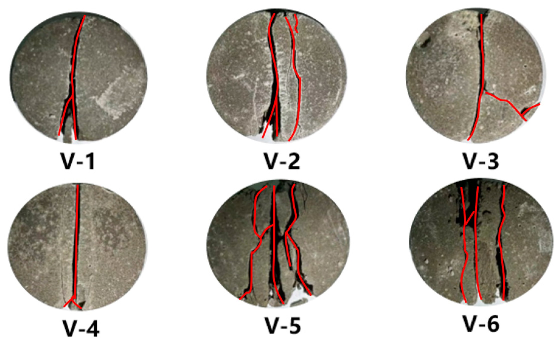
| Specimen Number | Diameter D (mm) | Thickness H (mm) | Ultimate Load Pmax (N) | Tensile Strength σt (MPa) |
|---|---|---|---|---|
| V-1 | 24.28 | 14.12 | 1738 | 3.23 |
| V-2 | 24.54 | 14.52 | 1398 | 2.50 |
| V-3 | 24.46 | 14.06 | 2011 | 3.72 |
| V-4 | 24.42 | 13.15 | 1179 | 2.34 |
| V-5 | 24.20 | 13.48 | 1808 | 3.53 |
| V-6 | 24.34 | 14.32 | 1481 | 2.71 |
| Mean value | 24.37 | 13.94 | 1602 | 3.01 |
Disclaimer/Publisher’s Note: The statements, opinions and data contained in all publications are solely those of the individual author(s) and contributor(s) and not of MDPI and/or the editor(s). MDPI and/or the editor(s) disclaim responsibility for any injury to people or property resulting from any ideas, methods, instructions or products referred to in the content. |
© 2024 by the authors. Licensee MDPI, Basel, Switzerland. This article is an open access article distributed under the terms and conditions of the Creative Commons Attribution (CC BY) license (https://creativecommons.org/licenses/by/4.0/).
Share and Cite
Yang, L.; Zhang, J.; Shen, J.; Ji, H. Study on the Compressive and Tensile Properties of Latex-Modified Cement Stone. Materials 2024, 17, 4868. https://doi.org/10.3390/ma17194868
Yang L, Zhang J, Shen J, Ji H. Study on the Compressive and Tensile Properties of Latex-Modified Cement Stone. Materials. 2024; 17(19):4868. https://doi.org/10.3390/ma17194868
Chicago/Turabian StyleYang, Lianzhi, Jie Zhang, Jiyun Shen, and Hongfei Ji. 2024. "Study on the Compressive and Tensile Properties of Latex-Modified Cement Stone" Materials 17, no. 19: 4868. https://doi.org/10.3390/ma17194868