Article

Stress-Strain Behavior and Strength Development of High-Amount Phosphogypsum-Based Sustainable Cementitious Materials

School of Resources and Safety Engineering, Central South University, Changsha 410083, China
*
Author to whom correspondence should be addressed.
Materials 2024, 17(19), 4927; https://doi.org/10.3390/ma17194927
Submission received: 25 August 2024 / Revised: 19 September 2024 / Accepted: 30 September 2024 / Published: 9 October 2024

Abstract

:
Phosphogypsum is a common industrial solid waste that faces the challenges of high stockpiling and low utilization rates. This study focuses on the mechanical properties and internal characteristics of cementitious materials with a high phosphogypsum content. Specifically, we examined the effects of varying amounts of ground granulated blast furnace slag (5–28%), fly ash (5–20%), and hydrated lime (0.5–2%) on the stress–strain curve, unconfined uniaxial compressive strength, and elastic modulus (E50) of these materials. The test results indicate that increasing the ground granulated blast furnace slag content can significantly enhance the mechanical properties of phosphogypsum-based cementitious materials. Additionally, increasing the fly ash content can have a similar beneficial effect with an appropriate amount of hydrated lime. Furthermore, microscopic analysis of the cementitious materials using a scanning electron microscope revealed that the high sulfate content in phosphogypsum leads to the formation of calcium aluminate as the main product. Concurrently, a continuous reaction of the raw materials contributes to the strength development of the cementitious materials over time. The results could provide a novel method for improving the reusing phosphogypsum amount in civil engineering materials.

1. Introduction

Ordinary Portland Cement (OPC), as a common cementitious material, is in high demand in the road and construction industries. However, the cost of OPC production and the accompanying environmental pollution have been unresolved issues for OPC as a cementitious material. The cement industry generally requires 1.2 tonnes of hydrated limestone and 0.3 tonnes of clay to produce one tonne of cement clinker [1]. In the process of producing one tonne of OPC, 700 kg of carbon dioxide is emitted into the atmosphere [2,3,4,5,6], as well as other toxic and harmful gasses [7,8,9,10]. Therefore, many scholars are committed to researching and developing low-cost green cementitious materials that can replace OPC [11,12,13]. Industrial production generates a large amount of solid waste [14,15,16,17]. These solid wastes, at present, are mainly disposed of at landfills with low comprehensive utilization [18,19,20,21,22]. Therefore, preparing low-cost green cementitious materials using various types of solid wastes is a pathway with great potential for development [23,24,25,26,27,28].
Phosphogypsum (PG), as a typical industrial solid waste, is generally produced as a by-product from the production of phosphoric acid. It is primarily composed of calcium sulfate dihydrate, along with impurities such as soluble phosphorus, fluorine, and heavy metals [29,30]. It was reported that approximately five tonnes of PG are generated in the production of one tonne of phosphoric acid. The global production of PG is about 300 million tonnes per year [31,32]. Its mass utilization would be 10–15% under ideal conditions [33]. The use of PG to prepare cementitious materials has been studied [34,35,36]. Min et al. [37] used PG, FA, lime, and cement to prepare cementitious materials. They found that relying on the interaction between the raw materials, they could obtain a cementitious material with excellent comprehensive performance. Xu et al. [38] mixed phosphonyls with iron tailings to prepare cementitious materials. They concluded that phosphonyls could effectively promote the generation of calcium alumina in the cementitious system, fill the large pores in the system, and significantly improve the compressive strength of cementitious materials. Liu et al. [39] aimed to address the issues of long setting time and low early strength in gelling agents. They explored a novel approach by adding polymerized aluminum compounds to regulate the nucleation and growth of calcite. This research developed a low-carbon gelling agent based on waste gypsum and metallurgical slag. Zhang et al. [40] prepared a low-carbon calcium sulphoaluminate cement by replacing natural gypsum with PG. They discussed the mechanical properties and hydration mechanism of this new cement.
Previous studies show that although PG can provide a large amount of sulfate, it lacks the silicon and aluminum elements needed for hydration reactions [41]. Therefore, the synergistic reaction with substances containing more silicon and aluminum elements mixed with PG [42] can effectively enhance the mechanical properties of PG-based cementitious materials. However, at present, most studies use low-volume (<45%) PG to partially replace OPC as composite cementitious materials [43,44,45,46]. There is still a knowledge gap in using high-volume (50–90%) PG to fabricate cementitious material without OPC. Therefore, this study planned to prepare low-cost cementitious materials using high-volume PG without OPC. Additionally, other solid wastes containing some amount of silicon and aluminum elements, i.e., ground granulated blast furnace slag (GGBS), and fly ash (FA), are required. GGBS effectively enhances the strength growth of the cementitious material in the early stage, while FA ensures the strength increase in the later stage of the cementitious material. At the same time, PG can raise sufficient amounts of sulfate to facilitate the volcanic ash reaction process during this period.
The properties of the relevant cementitious materials in different aspects are represented by a number of other parameters [47,48,49], while the mechanical properties are generally characterized by parameters such as peak strength, stress–strain curves, E50, etc. [50,51]. Referring to previous scholars’ research on cementitious materials [52,53,54]. The following exploration of test results was carried out in this paper: (1) analyzing the effect of changes in the components of the cementitious materials on the mechanical properties of paste; (2) studying the relationship between compressive strength and E50 of paste; (3) determining the microstructure of paste based on the scanning electron microscope micrographs.

2. Experimental Program
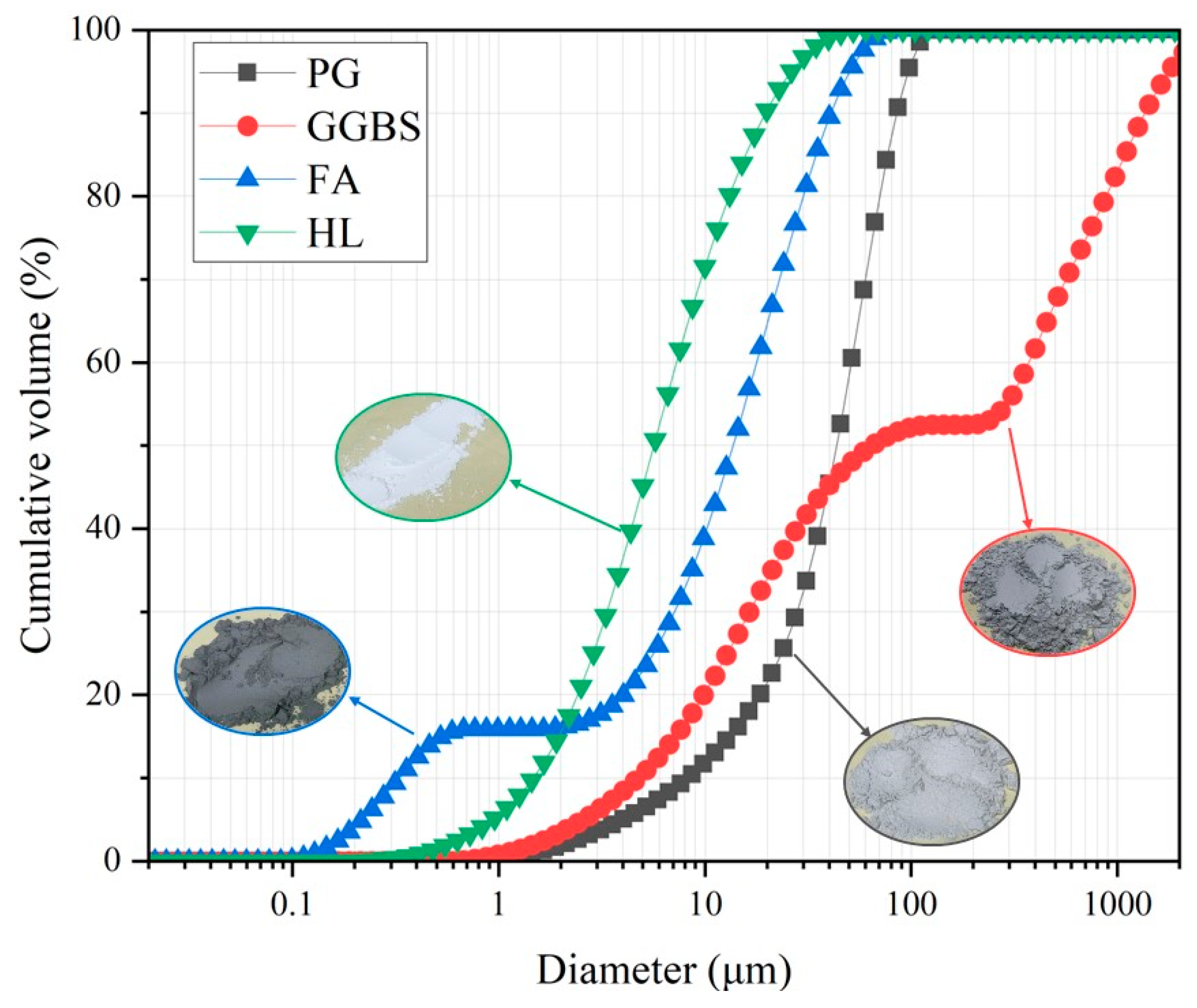
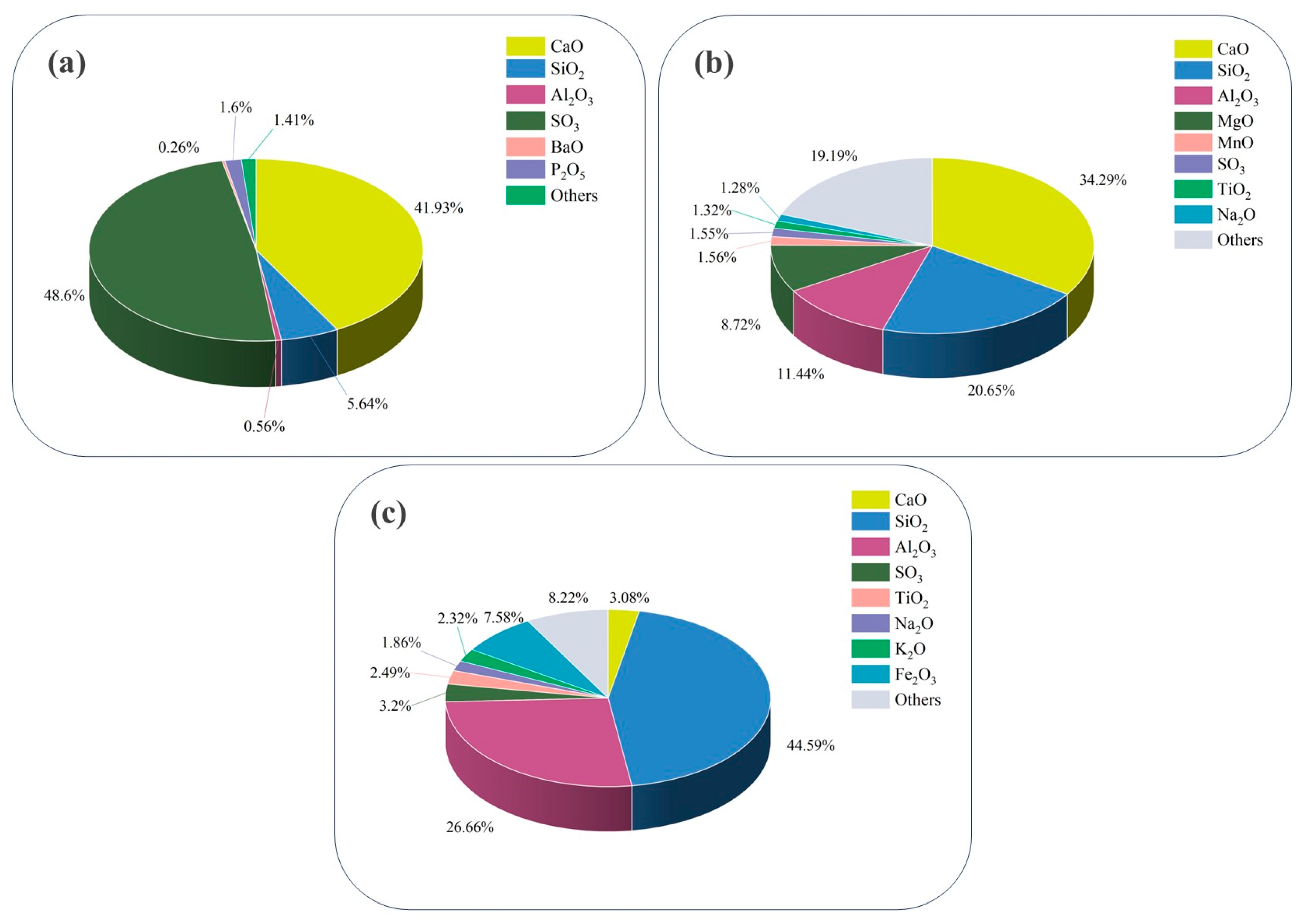
2.1. Raw Materials

The PG used in this study was sourced from Xifeng, Guizhou, China. Prior to use, it underwent water washing to remove attached pollutants. Based on pre-experimental research, the mass ratio of PG to water was 1:3, with stirring conducted for a total of half an hour. The GGBS, with S95-grade activity, was procured from the Baifeng Mineral Products Processing Plant, Shijiazhuang, China. F-grade FA was obtained from Longjiang FA Development and Utilisation Co. (Heilongjiang, China). Hydrated lime (HL) from Shanghai McLean Biochemical Technology Co. (Shanghai, China) was added to the reaction system to enhance the volcanic ash reaction. The particle size analysis of PG, GGBS, and FA was conducted using a Mastersizer 3000 laser diffraction particle size analyzer, with the results illustrated in Figure 1. The d50 values for PG, GGBS, FA, and HL were 50.5 μm, 73.7 μm, 15.2 μm, and 4.9 μm, respectively.
In this study, an X-ray fluorescence spectrometer (XRF) was used to analyze the main chemical constituents of solid waste. The results are shown in Figure 2. The main components of PG were 41.9% CaO and 48.6% SO3. GGBS was mainly composed of 34.3% CaO, 20.6% SiO2, and 11.4% Al2O3. In contrast, FA was composed of 44.6% SiO2 and 26.7% Al2O3.

2.2. Test Method

To examine the effects of three raw materials on the mechanical properties of PG-based paste specimens, the experimental design involved fixing the content of two raw materials while varying the content of the third. The raw material mixing for the cementitious materials was designed based on findings from previous laboratory studies [55]. Using the two groups G-1 and G-2 from Table 1 as examples, this study explores the impact of varying GGBS content on the properties of the cementitious materials, while maintaining constant levels of FA and HL. Given that PG, at a dosage greater than 50%, can serve as both a calcium source and a provider of sulfate ions, its individual variation is not considered in this research [55]. Table 1, Table 2 and Table 3 provide specific content information for each group. Based on previous laboratory findings, the water-to-binder ratio of paste was fixed at 0.5.
Figure 3 illustrates the specimen preparation process and testing apparatus. Firstly, dry PG, GGBS, FA, and HL were mixed for two minutes using a planetary mixer to obtain a homogeneous mixture. A corresponding mass of water was then added and mixed for another two minutes. Subsequently, the mixture was poured into 40 mm × 40 mm × 160 mm molds, and the poured molds were placed on a shaking table to eliminate air bubbles. Afterward, cling film was attached to the surface of the molds and maintained for three days before demolding. The specimens were further wrapped with cling film and cured in a constant temperature and humidity box (SHBY-60B, Cangzhou Yixuan Testing Instrument, Cangzhou, China) at 20 °C and 95% humidity.
The specimens’ unconfined compressive strength (UCS) at 28 days and 60 days was determined using a WHY-200/10 (Cangzhou Yixuan Testing Instrument) microcomputer-controlled compression tester. The corresponding data were analyzed to obtain the stress–strain curves. The UCS tests in this study refer to the Chinese standard GB/T17671 [56]. The uniaxial compressive strength result was the average of the test results of three specimens.
After the compressive strength test, specimens with a volume of 5 mm3, featuring natural fractures and flat surfaces, were selected. These specimens were dried in a constant-temperature oven at 60 °C until they reached a constant weight. Prior to testing, the samples were coated with gold foil to enhance conductivity. Scanning electron microscope images of these samples were obtained using a Phenom ProX (Thermo Fisher Scientific, Waltham, MA, USA) scanning electron microscope with an accelerating voltage of 10 KV.

3. Result and Discussion

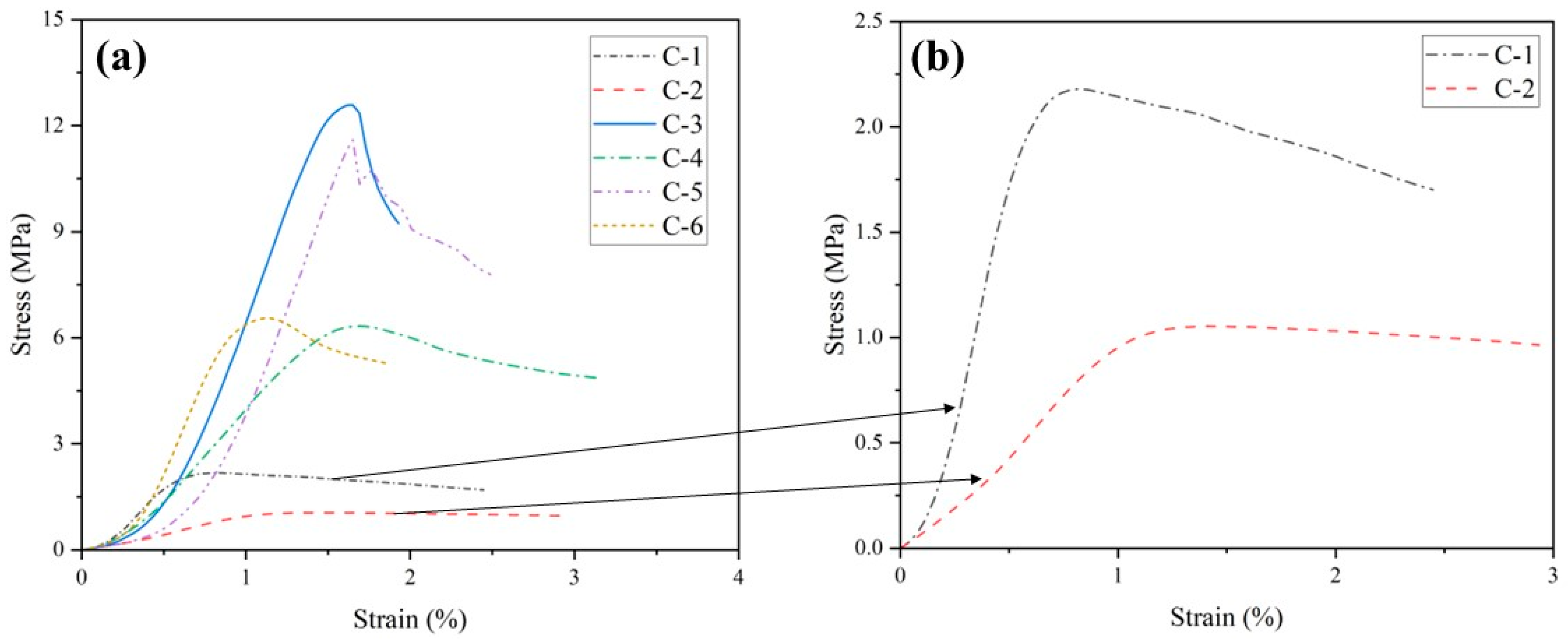
3.1. Stress and Strain

The corresponding stress–strain curve data for each group were exported and fitted to the curve when using the WHY-200/10 microcomputer-controlled compression tester to test the uniaxial compressive strength. The horizontal axis represents the axial strain of the cementitious material, while the vertical axis represents the axial stress of the cementitious material. Based on the change in stress rate, the stress–strain curve of the specimen is divided into four stages: compaction stage, elastic deformation stage, plastic deformation stage, and post-peak damage stage. In the compaction stage, the specimen closes the pores due to external pressure, resulting in a slow increase in stress with strain [57]. The elastic deformation stage is entered after the pores are closed, characterized by an approximately linear change in stress with strain. Subsequently, as the specimen continues to deform and the internal pores and cracks expand, it transitions into the plastic deformation stage under high pressure [58,59]. At this time, the stress growth rate of the specimen will continue to decline, reducing to zero when the peak stress is reached. Continuing to apply pressure to the specimen at this point will cause it to enter the post-peak damage stage. In this stage, the bearing capacity of the specimen will be reduced, and obvious cracks will appear on the surface [60].
Figure 4 illustrates the stress–strain curves for each group in Table 1 at 60 days. From the figure, it is evident that in the group with higher FA content, a higher GGBS content shortens the compaction stage of the specimen. This is because GGBS contains a certain amount of cement clinker and a significant amount of reactive silica-alumina, both of which fully participate in the hydration reaction [61]. This suggests that a significant amount of hydration products is generated inside the specimen to fill numerous pores. When the content of FA and HL is fixed, increasing the GGBS content in cementitious materials markedly enhances the slopes of the stress–strain curves in both the elastic and plastic deformation stages. This indicates a notable positive effect of increasing GGBS content on improving the deformation resistance of cementitious materials. Additionally, specimens in the group with a higher GGBS content ratio exhibited damage at higher strain values and demonstrated more ductile behavior.
Figure 5 illustrates the stress–strain curves for each group in Table 2 at 60 days. At higher GGBS and HL dosages, increasing the FA dosage significantly shortens the compaction stage of the cementitious materials. This indicates that sufficient amounts of GGBS and HL greatly enhance the participation of FA in the reaction, leading to the generation of more hydration products that fill internal pores. In contrast, with low GGBS and HL dosages, increasing the FA dosage prolongs the compaction stage of the specimens, suggesting that FA requires adequate alkalinity to dissolve the vitreous surface, thereby enabling the internal reactive silica-alumina to participate in the reaction [62]. After entering the ascending branch of the elastic deformation stage and the plastic deformation stage, increasing the FA content was able to increase the slope, indicating that FA participated in the reaction system in all groups and improved the deformation resistance of the specimens. However, the elevation of FA content decreases the failure strain values of the specimens, indicating a gradual transition from ductile to brittle specimens.
Figure 6 illustrates the stress–strain curves at 60 days for the groups in Table 3. From the figure, it can be seen that the compaction stages of the group with high HL content are all lower than those of the group with low HL content, indicating that HL can effectively neutralize the residual acid of PG and promote the participation of GGBS and FA in the reaction [63] so that there are enough hydration products inside the specimen to fill the pores. If the GGBS and FA content is low, the slopes of the group with high HL content will be lower than that of the group with low HL content in both the elastic deformation stage and plastic deformation stage, indicating that too much HL will be harmful to the deformation resistance of the specimen. However, if the content of GGBS and FA is increased, the HL will be fully utilized, increasing the specimens’ deformation resistance. The effect of HL content on the failure strain of the specimen is related to the content of other raw materials. Based on the high content of GGBS and FA, increasing the content of HL will make the specimen reach the failure strain value earlier and show higher brittleness. However, if the HL content is increased based on low GGBS and FA content, the specimen reaches the failure strain value later and shows higher ductility.

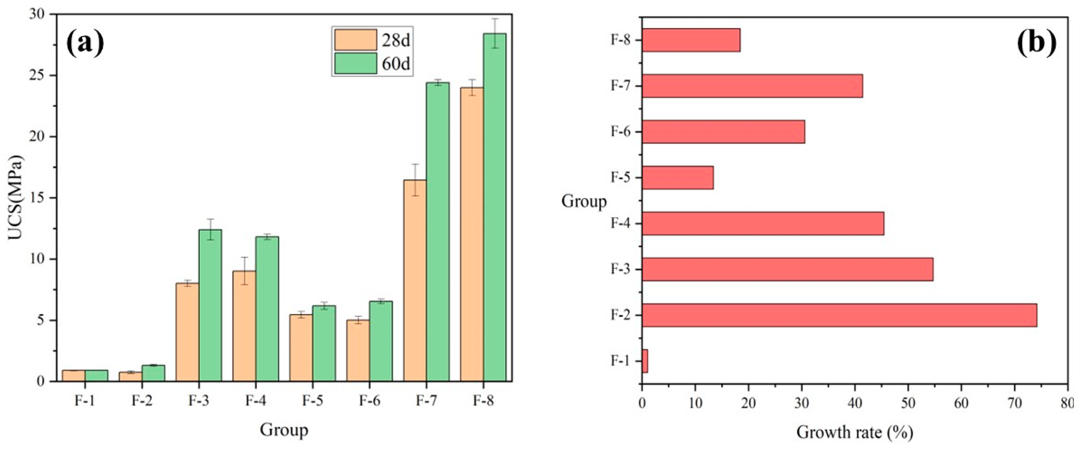
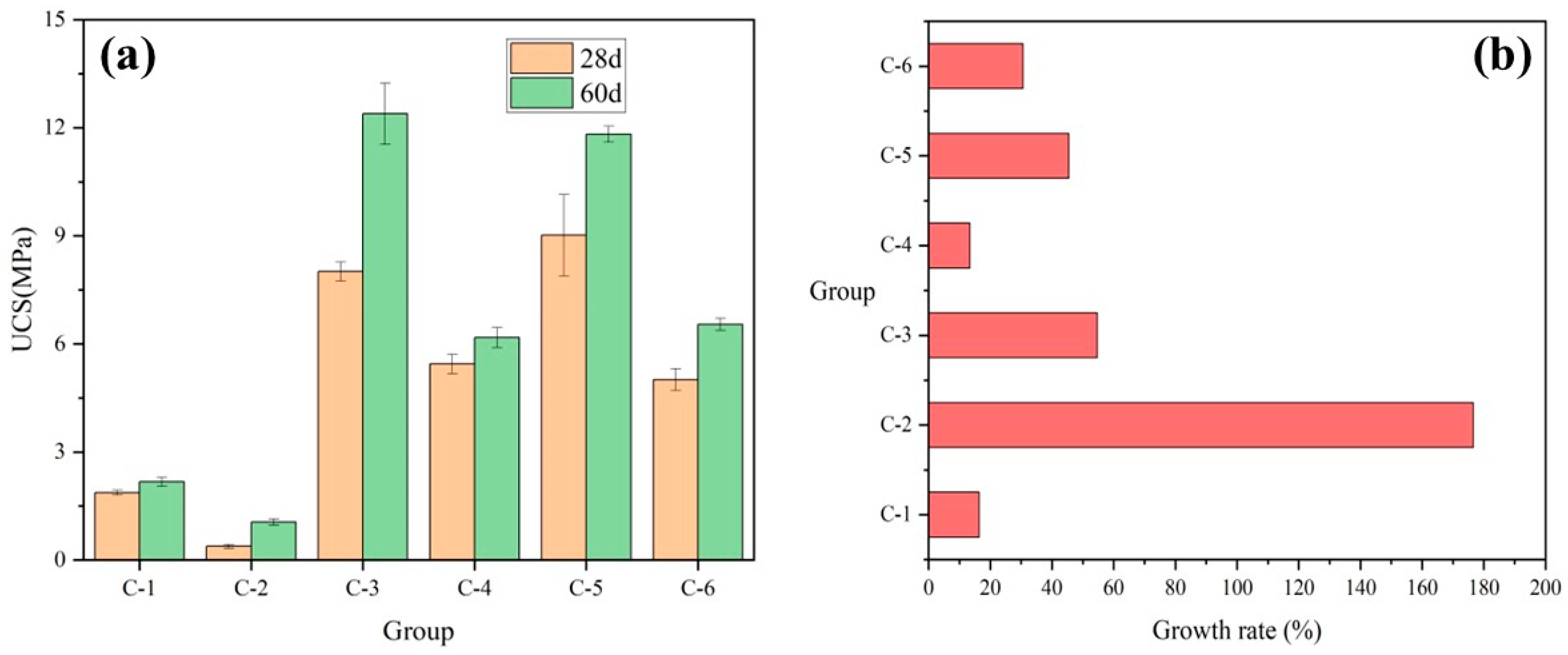
3.2. Compressive Strength

Figure 7a demonstrates the UCS at 28 and 60 days for each group of Table 1. Figure 7b demonstrates the growth rate of each group’s strength at 60 days relative to 28 days for different GGBS content, calculated as shown in Equation (1). It can be observed that the strength of specimens with high GGBS content is significantly higher than that of specimens with low GGBS content, regardless of the variation in FA and HL content. This is attributed to the fact that GGBS contains a certain amount of cement clinker and a large amount of active silica-alumina, effectively enhancing the strength of cementitious materials [61]. The presence of high GGBS content can effectively ensure the strength growth value of the specimens from 28 days of maintenance to 60 days. The strength growth rate of the high GGBS content group was higher than that of the low GGBS content group, except for G-4. The strength growth rate in the G-3 group was 74%, significantly higher than the 18% observed in the G-4 group. This difference is attributed to the much higher initial strength value of the G-3 group at 28 days. The G-4 group formulations outperform the others in this study.
G r o w t h   r a t e % = U C S 60 d U C S 28 d U C S 28 d
Figure 8a illustrates the UCS of each group of Table 2 at 28 and 60 days. Figure 8b illustrates the growth rate of each group’s strength at 60 days relative to 28 days for different FA contents. As shown in the figure, while keeping the low HL content constant, the strength of the high FA content group (F-4) is lower than that of the low FA content group (F-5). Conversely, the strength of the high FA content group is higher than that of the low FA content group for all other ratio groups, indicating that to promote FA’s participation in the reaction, it is necessary to ensure a certain level of alkalinity [64]. Thus, due to high alkalinity, the strength growth rate of 30% in the high FA content group (F-6) was significantly higher than the 13% strength growth rate in the low FA content group (F-5).
Figure 9a illustrates the UCS of each group of Table 3 at 28 and 60 days. Figure 9b illustrates the growth rate of each group at 60 days strength relative to 28 days strength for different HL contents. It can be seen from the figure that the high HL admixture has a negative effect on the hydration reaction inside the specimen [65]. The strengths of the specimens in the high HL content group are much lower than those in the low HL content group. While keeping the low content of GGBS and FA unchanged, the strength growth rate of the high HL content group (C-2) was 176%, which was 16% higher than the strength growth rate of the low HL content group (C-1). Conversely, other groups exhibit the opposite trend: the C-4 strength growth rate of 13% is lower than the C-3 strength growth rate of 54%, and the C-6 strength growth rate of 30% is lower than the C-5 strength growth rate of 45%. This suggests that the low lime content group still requires a certain amount of GGBS to undergo hydrolysis reaction [66], generating HL crystals to maintain the alkalinity of the reaction system.

3.3. Prediction Model

As shown in Table 4 below, the different dosages of raw materials used in this study were grouped into three level values. A reasonable prediction model was constructed using UCS at a curing time of 60 days as an example.
The corresponding simplified mathematical model is shown in Equation (2). Table 5 displays the statistical indicators of the constructed model, including essential metrics such as the F-value, p-value, and R2.
U C S 60 d = 9.89 + 10.88   A + 0.63   B 2.63   C + 1.26   A B 1.82   A C + 0.23   B C + 2.75   A 2 + 0.91   B 2 1.57   C 2
The F-value for the model in Table 5 is 28.17, indicating that the model is significant. The model has a probability of 0.09%, and the observed large F-value is not attributed to noise. In this study, the p-value for the model is less than 0.05, affirming the significance of the model. Meanwhile, the R2 value of the model is 0.9807, indicating that the model accurately represents the actual situation [67,68].
The comparison of experimental and predicted UCS is shown in Figure 10. Using the model fitted to the test data, the UCS values for a curing time of 60 days can be predicted. The predicted values are generally comparable to the experimental values, with a root mean square error (RMSE) of only 1.268 MPa. Consequently, the reliability of the fitted model is considered high.
Based on the cementitious materials prepared in this study, two experimental groups with different ratios were created. A compressive strength test was conducted after 60 days of curing. The results were used to verify the accuracy of the previously constructed model, as shown in Table 6. The findings demonstrate that the model possesses a notable degree of generalizability.

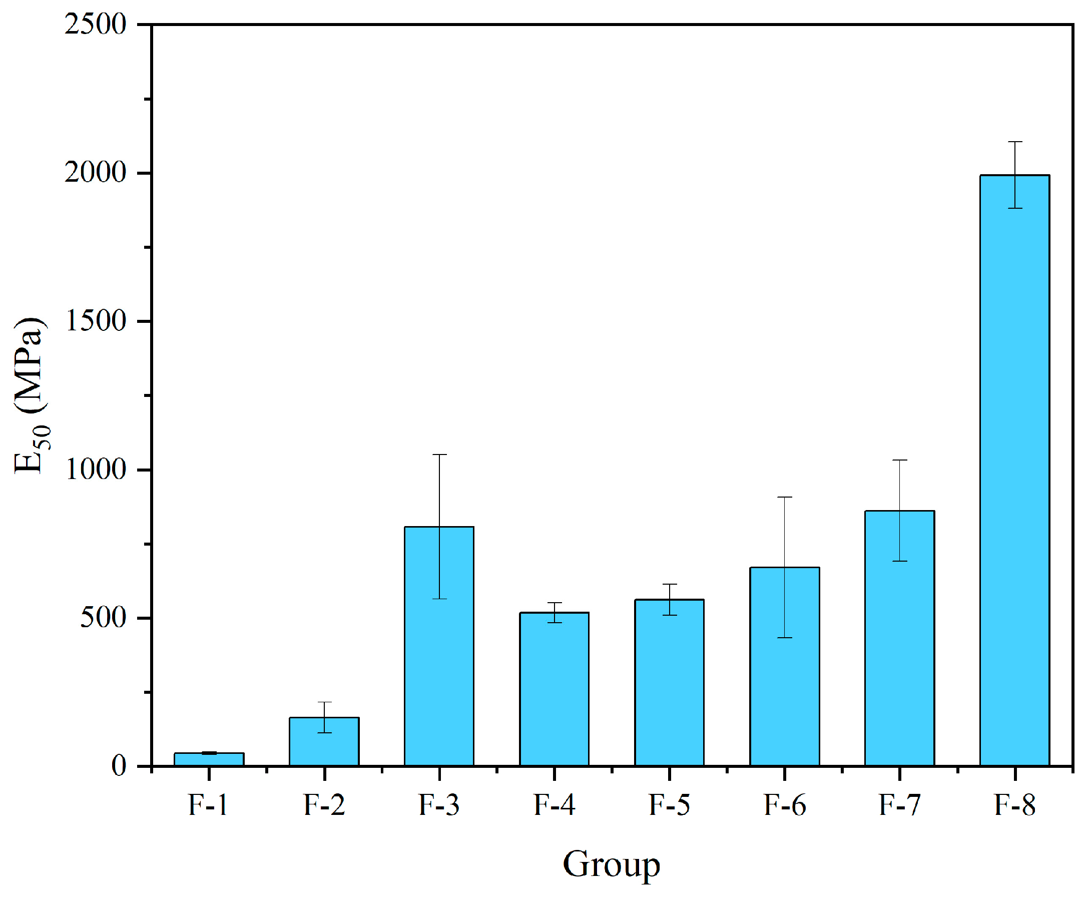
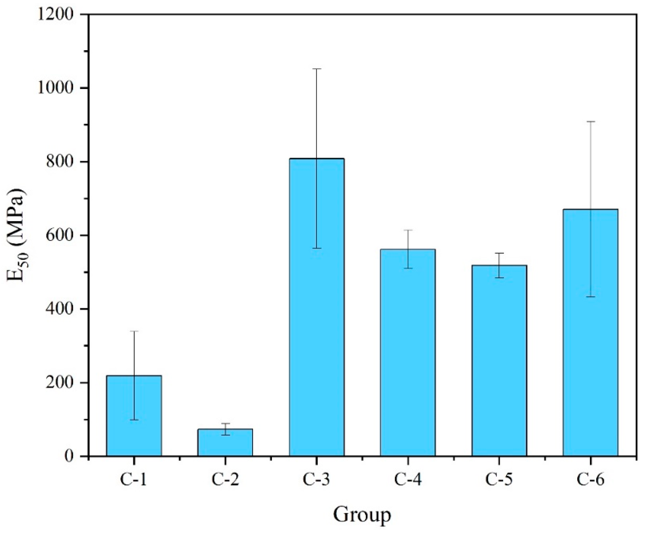
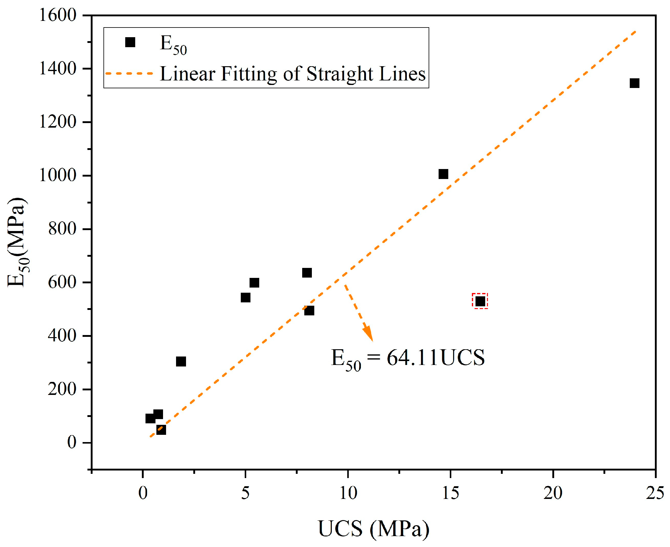
3.4. Elastic Modulus

The E50 is a constant of proportionality of material over the range of elastic deformation and is a parameter that clearly reflects the mechanical properties of the prepared cementitious material [69,70]. In this study, the constant of proportionality of the prepared cementitious material at 50% peak stress is taken and calculated as shown below:
E 50 = σ 50 ε 50
where E 50 is the constant of proportionality of the cementitious material at 50% peak stress, MPa. The σ 50 is the 50% peak stress of the cementitious material, MPa. The ε 50 is the the strain value at the 50% peak stress of the cementitious material.
The following Figure 11 shows the E50 for different GGBS content groups. Elevated GGBS content significantly increases the E50 of the specimens, with the highest group, G-4, reaching an E50 of 2000 MPa, nearly 12 times higher compared to the corresponding low GGBS content group G-3.
The following Figure 12 shows the E50 for different FA content groups. Based on low HL content, increasing the FA content decreases the E50 of the specimens (F-3 vs. F-4). However, increasing the FA content in the remaining groups significantly increases the E50, which is consistent with the change in the strength of the specimens. The highest of these groups, F-8, improved nearly three times compared to F-7.
The following Figure 13 shows the E50 for different HL content groups. Based on high FA content, increasing the HL content enhances the E50 to some extent (C-5 vs. C-6), which is related to the need for a certain alkalinity of the FA. Whereas, increasing the HL content for the other groups significantly reduces the E50.
Based on the UCS and E50 discussed above, the corresponding data for each group were curve-fitted to build the model equations, as shown in Figure 14 (data points identified with dashed boxes in the figure are discrete points). The E50 of each group has a gradually increasing trend with UCS, and the higher the UCS, the larger the E50. The corresponding linear correlation equation is E50 = 64.11UCS, and the correlation coefficient of the equation is R2 = 0.95, which is highly reliable.

3.5. SEM

In this study, the typical microstructure of this system was analyzed using the optimized proportioning group based on the strength results as a representative specimen. The results are shown in Figure 15. From Figure 15d, it can be seen that the main product of the reaction of the cementitious materials is ettringite, which is associated with the high sulfate content provided by PG [25]. As shown in Figure 15b,c, a certain amount of PG, GGBS, and FA is still present within the collodion material, indicating that the hydration reaction has not been fully completed in a short period. In the later stages of the hydration reaction, the glassy layer on the surface of the FA gradually dissolves. This dissolution releases reactive silica-aluminum compounds [71,72]. These reactive substances react with the abundant sulfates in the system, producing adequate amounts of ettringite to fill the pores within the cementitious material. Consequently, the cementitious material is expected to exhibit significant strength growth in the later period (60 days).

4. Conclusions

This study analyzes the mechanical properties and microstructure of a PG-based cementitious material developed using various solid wastes as raw materials to improve the reusing of PG in civil engineering materials. Different raw materials’ effects on the cementitious material’s properties are clarified, and relevant fitting models are constructed. The main conclusions are as follows:
(1)
A high GGBS content (28%) can compensate for the pores inside the cementitious material and improve deformation resistance. Similarly, a high FA content (20%) can achieve the same function with sufficient alkalinity. However, excessive alkalinity negatively affects the material’s performance.
(2)
High GGBS content significantly improves the UCS of cementitious materials. Moreover, increasing FA content under appropriate HL conditions also enhances UCS.
(3)
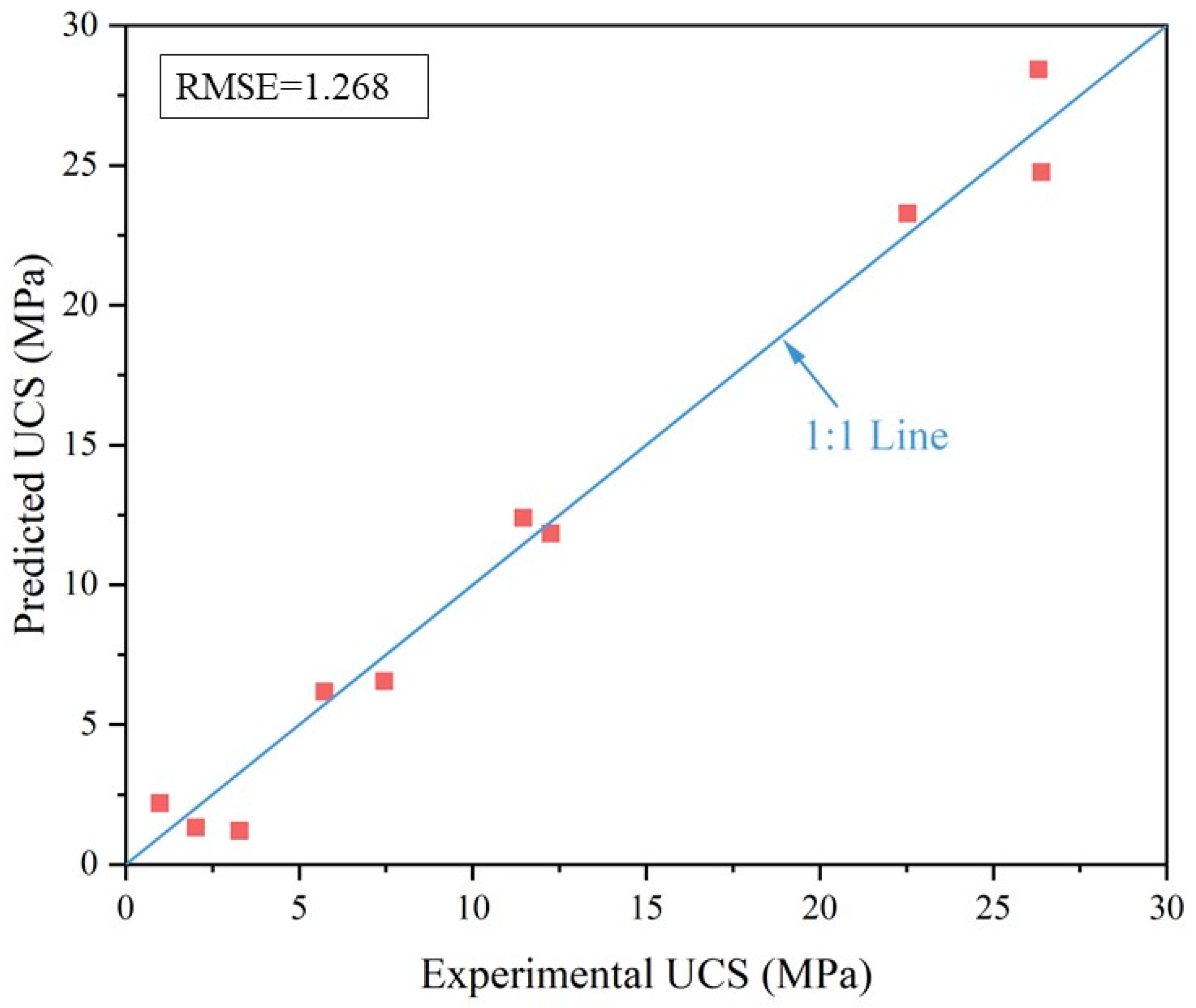
A prediction model was constructed based on the UCS of cementitious materials. The statistical indices of the constructed model indicate a certain degree of reliability, and the model’s predicted data are generally consistent with the test data.
(4)
The pattern of change in E50 and UCS of cementitious materials tends to be the same, so the relationship between the two is modeled as a linear equation, represented as E50 = 64.11UCS.
(5)
SEM results indicate that ettringite primarily fills the pores within the studied cementitious material. As the curing age increases, the unreacted materials in the system gradually participate in the hydration reaction, continuously producing ettringite to further fill the pores of the cementitious material.

Author Contributions

Conceptualization, Formal analysis, Investigation, Writing—original draft preparation, Y.S., H.W. and Y.L.; Formal analysis, Software, Y.S., H.W., Y.L. and Y.M.; Conceptualization, Writing—review and editing, Y.S., H.W., Y.L. and X.L. All authors have read and agreed to the published version of the manuscript.

Funding

This research was supported by the National Natural Science Foundation of China (grant no. 42177160, Grant No. 52304114) and the Natural Science Foundation of Hunan Province (grant no. 2024JJ6510).

Institutional Review Board Statement

Not applicable.

Informed Consent Statement

Not applicable.

Data Availability Statement

The authors confirm that the data supporting the findings of this study are available within the article.

Conflicts of Interest

The authors declare no conflicts of interest.

References

  1. Kumar, S.; Kumar, R.; Bandopadhyay, A. Innovative methodologies for the utilisation of wastes from metallurgical and allied industries. Resour. Conserv. Recycl. 2006, 48, 301–314. [Google Scholar] [CrossRef]
  2. Hasanbeigi, A.; Price, L.; Lu, H.; Lan, W. Analysis of energy-efficiency opportunities for the cement industry in Shandong Province, China: A case study of 16 cement plants. Energy 2010, 35, 3461–3473. [Google Scholar] [CrossRef]
  3. Naqi, A.; Jang, J. Recent Progress in Green Cement Technology Utilizing Low-Carbon Emission Fuels and Raw Materials: A Review. Sustainability 2019, 11, 537. [Google Scholar] [CrossRef]
  4. Rashad, A.M.; Zeedan, S.R. The effect of activator concentration on the residual strength of alkali-activated fly ash pastes subjected to thermal load. Constr. Build. Mater. 2011, 25, 3098–3107. [Google Scholar] [CrossRef]
  5. Poudyal, L.; Adhikari, K. Environmental sustainability in cement industry: An integrated approach for green and economical cement production. Resour. Environ. Sustain. 2021, 4, 100024. [Google Scholar] [CrossRef]
  6. Zhi, X.; An, X.P. Low carbon technology roadmap of China cement industry. J. Sustain. Cem.-Based Mater. 2023, 12, 771–774. [Google Scholar] [CrossRef]
  7. Rashad, A.M. Metakaolin as cementitious material: History, scours, production and composition—A comprehensive overview. Constr. Build. Mater. 2013, 41, 303–318. [Google Scholar] [CrossRef]
  8. Valipour, M.; Yekkalar, M.; Shekarchi, M.; Panahi, S. Environmental assessment of green concrete containing natural zeolite on the global warming index in marine environments. J. Clean. Prod. 2014, 65, 418–423. [Google Scholar] [CrossRef]
  9. Liu, C.; Tian, J.; Cheng, K.; Xu, X.; Wang, Y.; Liu, X.; Liu, Z.; Bian, R.; Zhang, X.; Xia, S.; et al. Topsoil microbial biomass carbon pool and the microbial quotient under distinct land-use types across China: A data synthesis. Soil Sci. Environ. 2023, 2, 5. [Google Scholar] [CrossRef]
  10. Yue, Q.; Cheng, K.; Sheng, J.; Wang, L.; Ji, C.; Zhang, Y.; Zheng, J. Greenhouse gas emissions from managed freshwater wetlands under intensified aquaculture. Soil Sci. Environ. 2023, 2, 3. [Google Scholar] [CrossRef]
  11. Ahmad, J.; Kontoleon, K.J.; Al-Mulali, M.Z.; Shaik, S.; El Ouni, M.H.; El-Shorbagy, M.A. Partial Substitution of Binding Material by Bentonite Clay (BC) in Concrete: A Review. Buildings 2022, 12, 634. [Google Scholar] [CrossRef]
  12. Wang, H.; Zentar, R.; Wang, D. Rheological Characterization of Fine-Grained Sediments under Steady and Dynamic Conditions. Int. J. Geomech. 2022, 22, 04021260. [Google Scholar] [CrossRef]
  13. Wang, H.; Zentar, R.; Wang, D. Predicting the compaction parameters of solidified dredged fine sediments with statistical approach. Mar.Geores.Geotechnol. 2023, 41, 195–210. [Google Scholar] [CrossRef]
  14. Ren, F.-R.; Chen, K.-J.; Tian, Z.; Zhang, Y. The investment and treatment efficiencies of industrial solid waste in China’s Yangtze and non-Yangtze River Economic Belts. J. Mater. Cycles Waste Manag. 2022, 24, 900–916. [Google Scholar] [CrossRef]
  15. Wu, C. Investigation of foundation theory of safety & security complexity. J. Saf. Sustain. 2024, 1, 14–25. [Google Scholar]
  16. Zhang, Y.; Qi, H.; Li, C.; Zhou, J. Enhancing safety, sustainability, and economics in mining through innovative pillar design: A state-of-the-art review. J. Saf. Sustain. 2024, 1, 53–73. [Google Scholar] [CrossRef]
  17. Zhao, S.; Wang, F.Y.; Tan, D.Y.; Yang, A.W. A deep learning informed-mesoscale cohesive numerical model for investigating the mechanical behavior of shield tunnels with crack damage. Structures 2024, 66, 106902. [Google Scholar] [CrossRef]
  18. Zhou, B.Y.; Sun, C.X.; Yi, H.T. Solid Waste Disposal in Chinese Cities: An Evaluation of Local Performance. Sustainability 2017, 9, 2234. [Google Scholar] [CrossRef]
  19. Ramanayaka, S.; Tsang, D.C.W.; Hou, D.Y.; Ok, Y.S.; Vithanage, M. Green synthesis of graphitic nanobiochar for the removal of emerging contaminants in aqueous media. Sci. Total Environ. 2020, 706, 135725. [Google Scholar] [CrossRef]
  20. Wang, L.; Chen, L.; Tsang, D.C.W.; Li, J.S.; Yeung, T.L.Y.; Ding, S.M.; Poon, C.S. Green remediation of contaminated sediment by stabilization/solidification with industrial by-products and CO2 utilization. Sci. Total Environ. 2018, 631–632, 1321–1327. [Google Scholar] [CrossRef]
  21. Adesina, A. Performance and sustainability overview of sodium carbonate activated slag materials cured at ambient temperature. Resour. Environ. Sustain. 2021, 3, 100016. [Google Scholar] [CrossRef]
  22. Hu, J.; Wang, Y.; Zhang, S.; Chang, T.; Sun, L. Preparation and classification, hydration mechanism and durability of magnesium cementitious materials. J. Min. Sci. Technol. 2023, 8, 856–867. [Google Scholar] [CrossRef]
  23. Yang, P.; Liu, L.; Suo, Y.; Qu, H.; Xie, G.; Zhang, C.; Deng, S.; Lv, Y. Investigating the synergistic effects of magnesia-coal slag based solid waste cementitious materials and its basic characteristics as a backfill material. Sci. Total Environ. 2023, 880, 163209. [Google Scholar] [CrossRef] [PubMed]
  24. Wang, H.; Zentar, R.; Wang, D.; Ouendi, F. New Applications of Ordinary Portland and Calcium Sulfoaluminate Composite Binder for Recycling Dredged Marine Sediments as Road Materials. Int. J. Geomech. 2022, 22, 04022068. [Google Scholar] [CrossRef]
  25. Zentar, R.; Wang, H.; Wang, D. Comparative study of stabilization/solidification of dredged sediments with ordinary Portland cement and calcium sulfo-aluminate cement in the framework of valorization in road construction material. Constr. Build. Mater. 2021, 279, 122447. [Google Scholar] [CrossRef]
  26. Zhu, M.; Xie, G.; Liu, L.; Wang, R.; Ruan, S.; Yang, P.; Fang, Z. Strengthening mechanism of granulated blast-furnace slag on the uniaxial compressive strength of modified magnesium slag-based cemented backfilling material. Process Saf. Environ. Protect. 2023, 174, 722–733. [Google Scholar] [CrossRef]
  27. Liu, J.; Tan, X.; He, Y.; Zheng, k.; Wang, H.; He, Y.; Xie, N.; Wang, D. Semi-flexible pavement application of red mud-based cementitious materials. J. Chang. Univ. (Nat. Sci. Ed.) 2022, 42, 21–32. [Google Scholar] [CrossRef]
  28. Zhang, D.; Wang, A. A Review of the Properties and Engineering Applications of Geopolymer Cementitious Materials. J. Archit. Civ. Eng. 2020, 37, 13–38. [Google Scholar] [CrossRef]
  29. Calderón-Morales, B.R.S.; García-Martínez, A.; Pineda, P.; García-Tenório, R. Valorization of phosphogypsum in cement-based materials: Limits and potential in eco-efficient construction. J. Build. Eng. 2021, 44, 102506. [Google Scholar] [CrossRef]
  30. Cui, Y.; Bai, J.; Chang, I.S.; Wu, J. A systematic review of phosphogypsum recycling industry based on the survey data in China–applications, drivers, obstacles, and solutions. Environ. Impact Assess. Rev. 2024, 105, 107405. [Google Scholar] [CrossRef]
  31. Rashad, A.M. Phosphogypsum as a construction material. J. Clean. Prod. 2017, 166, 732–743. [Google Scholar] [CrossRef]
  32. Bilal, E.; Bellefqih, H.; Bourgier, V.; Mazouz, H.; Dumitraş, D.-G.; Bard, F.; Laborde, M.; Caspar, J.P.; Guilhot, B.; Iatan, E.-L.; et al. Phosphogypsum circular economy considerations: A critical review from more than 65 storage sites worldwide. J. Clean. Prod. 2023, 414, 137561. [Google Scholar] [CrossRef]
  33. Chernysh, Y.; Yakhnenko, O.; Chubur, V.; Roubík, H. Phosphogypsum Recycling: A Review of Environmental Issues, Current Trends, and Prospects. Appl. Sci. 2021, 11, 1575. [Google Scholar] [CrossRef]
  34. Li, X.; Zhou, Y.; Zhu, Q.; Zhou, S.; Min, C.; Shi, Y. Slurry Preparation Effects on the Cemented Phosphogypsum Backfill through an Orthogonal Experiment. Minerals 2019, 9, 31. [Google Scholar] [CrossRef]
  35. Min, C.; Shi, Y.; Liu, Z. Properties of cemented phosphogypsum (PG) backfill in case of partially substitution of composite Portland cement by ground granulated blast furnace slag. Constr. Build. Mater. 2021, 305, 124786. [Google Scholar] [CrossRef]
  36. Zhou, S.; Li, X.; Zhou, Y.; Min, C.; Shi, Y. Effect of phosphorus on the properties of phosphogypsum-based cemented backfill. J. Hazard. Mater. 2020, 399, 122993. [Google Scholar] [CrossRef]
  37. Chen, M.; Liu, P.; Kong, D.; Li, Y.; Chen, Y.; Cui, G.; Wang, J.; Yu, K.; Wu, N. Performance Study and Multi-Index Synergistic Effect Analysis of Phosphogypsum-Based Composite Cementitious Material. Coatings 2022, 12, 1918. [Google Scholar] [CrossRef]
  38. Xu, J.Q.; Chen, P.; Zhang, C.Y.; Yang, Y.H. Influence of phosphogypsum on mechanical properties and microstructure of iron tailings cementitious material. Arch. Civ. Mech. Eng. 2023, 24, 18. [Google Scholar] [CrossRef]
  39. Liu, X.; Tang, P.; Chen, W. Development of an ettringite-based low carbon binder by promoting the nucleation and Ostwald ripening process. Constr. Build. Mater. 2024, 427, 136282. [Google Scholar] [CrossRef]
  40. Zhang, J.; Cui, K.; Yang, Y.; Chang, J. Investigation on the preparation of low carbon cement materials from industrial solid waste phosphogypsum: Clinker preparation, cement properties, and hydration mechanism. J. Clean Prod. 2024, 452, 142203. [Google Scholar] [CrossRef]
  41. Min, C.; Li, X.; He, S.; Zhou, S.; Zhou, Y.; Yang, S.; Shi, Y. Effect of mixing time on the properties of phosphogypsum-based cemented backfill. Constr. Build. Mater. 2019, 210, 564–573. [Google Scholar] [CrossRef]
  42. Ma, F.; Chen, L.; Lin, Z.; Liu, Z.; Zhang, W.; Guo, R. Microstructure and Key Properties of Phosphogypsum-Red Mud-Slag Composite Cementitious Materials. Materials 2022, 15, 6069. [Google Scholar] [CrossRef] [PubMed]
  43. Dong, S.; Zhuo, Q.; Chen, L.; Wu, F.; Xie, L. Reuse of Pretreated Red Mud and Phosphogypsum as Supplementary Cementitious Material. Sustainability 2023, 15, 2856. [Google Scholar] [CrossRef]
  44. Huang, Y.; Lin, Z. Investigation on phosphogypsum-steel slag-granulated blast-furnace slag-limestone cement. Constr. Build. Mater. 2010, 24, 1296–1301. [Google Scholar] [CrossRef]
  45. Yang, X.; Jia, Y.; Yang, C.; He, X.; Jia, Y.; Xu, L. Research on formulation optimization and hydration mechanism of phosphogypsum-based filling cementitious materials. Front. Environ. Sci. 2022, 10, 1012057. [Google Scholar] [CrossRef]
  46. Zeng, L.-L.; Bian, X.; Zhao, L.; Wang, Y.-J.; Hong, Z.-S. Effect of phosphogypsum on physiochemical and mechanical behaviour of cement stabilized dredged soil from Fuzhou, China. Geomech. Energy Environ. 2021, 25, 100195. [Google Scholar] [CrossRef]
  47. Zhu, J.; Qu, Z.; Huang, Y.; Song, L.; Liu, S.; Min, H.; Li, Z. Investigating Mechanical Properties of Alkali-Activated Slag Cementitious Material for Load-Bearing Layer of Sandwich Panels. Materials 2023, 16, 6398. [Google Scholar] [CrossRef]
  48. Xu, Z.; Han, X.; Feng, K.; Zhang, W.; Ma, K. Improvement of Mechanical Properties and Microstructure of Cementitious Materials in a Hot-Dry Environment. Crystals 2022, 12, 981. [Google Scholar] [CrossRef]
  49. Jongpradist, P.; Jamsawang, P.; Kongkitkul, W. Equivalent void ratio controlling the mechanical properties of cementitious material-clay mixtures with high water content. Mar. Georesources Geotechnol. 2019, 37, 1151–1162. [Google Scholar] [CrossRef]
  50. Deng, Y.; Yan, C.; Zhang, J.; Yin, L.; Liu, S.; Yan, Y. Preparation and mechanical characterization of engineered cementitious composites with high-volume fly ash and waste glass powder. J. Clean. Prod. 2022, 333, 130222. [Google Scholar] [CrossRef]
  51. Sun, L.; Hao, Q.; Zhao, J.; Wu, D.; Yang, F. Stress strain behavior of hybrid steel-PVA fiber reinforced cementitious composites under uniaxial compression. Constr. Build. Mater. 2018, 188, 349–360. [Google Scholar] [CrossRef]
  52. Lu, D.; Du, X.; Ma, C.; Wang, Y. Study on static and dynamic stress–strain relationship of cement mortar material. Mater. Res. Innov. 2014, 18, S2-799–S2-805. [Google Scholar] [CrossRef]
  53. Kohees, M.; Rajeev, P.; Sanjayan, J.G. Stress-strain relationship of cement paste under triaxial compression. Proc. Inst. Civ. Eng.-Constr. Mater. 2022, 175, 233–241. [Google Scholar] [CrossRef]
  54. Zhou, J.-k.; Ge, L.-m. Effect of strain rate and water-to-cement ratio on compressive mechanical behavior of cement mortar. J. Cent. South Univ. 2015, 22, 1087–1095. [Google Scholar] [CrossRef]
  55. Shi, Y.; Li, Y.; Wang, H. Eco-friendly solid waste-based cementitious material containing a large amount of phosphogypsum: Performance optimization, micro-mechanisms, and environmental properties. J. Clean. Prod. 2024, 471, 143335. [Google Scholar] [CrossRef]
  56. GB/T 17671-2021; Test Method of Cement Mortar Strength (ISO Method). Standardization Administration of the People’s Republic of China: Beijing, China, 2021; p. 24.
  57. Huang, K.; Ma, Q.; Ma, D.; Bosco, M. Effect of Basalt Fiber on Static and Dynamic Mechanical Properties of Metakaolin-Based Cement Clay. Adv. Civ. Eng. 2020, 2020, 1359163. [Google Scholar] [CrossRef]
  58. Zhang, J.; Deng, A.; Jaksa, M. Enhancing mechanical behavior of micaceous soil with jute fibers and lime additives. J. Rock Mech. Geotech. Eng. 2021, 13, 1093–1100. [Google Scholar] [CrossRef]
  59. Mirzababaei, M.; Miraftab, M.; Mohamed, M.; McMahon, P. Unconfined Compression Strength of Reinforced Clays with Carpet Waste Fibers. J. Geotech. Geoenviron. Eng. 2013, 139, 483–493. [Google Scholar] [CrossRef]
  60. Wang, D.; Wang, H.; Di, S. Mechanical properties and microstructure of magnesia–fly ash pastes. Road Mater. Pavement Des. 2018, 20, 1243–1254. [Google Scholar] [CrossRef]
  61. Zhang, F.; Li, Y.; Zhang, J.; Gui, X.; Zhu, X.; Zhao, C. Effects of slag-based cementitious material on the mechanical behavior and heavy metal immobilization of mine tailings based cemented paste backfill. Heliyon 2022, 8, e10695. [Google Scholar] [CrossRef]
  62. Ma, W.; Brown, P.W. Hydrothermal reactions of fly ash with Ca(OH)2 and CaSO4·2H2O. Cem. Concr. Res. 1997, 27, 1237–1248. [Google Scholar] [CrossRef]
  63. Mashifana, T.; Okonta, F.N.; Ntuli, F. Geotechnical Properties and Application of Lime Modified Phosphogypsum Waste. Mater. Sci. 2018, 24, 312–318. [Google Scholar] [CrossRef]
  64. Zhang, S.; Li, V.C.; Ye, G. Micromechanics-guided development of a slag/fly ash-based strain-hardening geopolymer composite. Cem. Concr. Compos. 2020, 109, 103510. [Google Scholar] [CrossRef]
  65. Seo, J.H.; Park, S.M.; Yang, B.J.; Jang, J.G. Calcined Oyster Shell Powder as an Expansive Additive in Cement Mortar. Materials 2019, 12, 1322. [Google Scholar] [CrossRef] [PubMed]
  66. Sevim, O.; Sengul, C.G.; Kartal, S.; Toklu, K.; Caglar, Y. Effect of Supplementary Cementitious Materials with Similar Specific Surface Area on Cementitious Composite Systems. J. Test. Eval. 2023, 51, 2971–2985. [Google Scholar] [CrossRef]
  67. Lin, T.; Wang, C.; Yousfani, S.; Wang, W.; Qian, X.; Xun, Z. Study on extraction technology of bamboo fiber by response surface. Acta Mater Compos. Sin 2018, 35, 876–884. [Google Scholar]
  68. Xu, X.H.; He, M.Z. Experimental Design and Application of Design-Expert and SPSS; Science Press: Beijing, China, 2010. (In Chinese) [Google Scholar]
  69. He, Z.-H.; Zhan, P.-M.; Du, S.-G.; Liu, B.-J.; Yuan, W.-B. Creep behavior of concrete containing glass powder. Compos. Part B-Eng. 2019, 166, 13–20. [Google Scholar] [CrossRef]
  70. Wang, P.; Xie, M.; Liu, L. Study on Early Shrinkage and Mechanical Properties of Concrete with Various Cementitious Materials. Buildings 2022, 12, 1543. [Google Scholar] [CrossRef]
  71. Van Roode, M.; Douglas, E.; Hemmings, R.T. X-ray diffraction measurement of glass content in fly ashes and slags. Cem. Concr. Res. 1987, 17, 183–197. [Google Scholar] [CrossRef]
  72. Diamond, S.; Kilgour, C.L. A Procedure for the Interpretation of Fly Ash Particle Size Data. Mater. Res. Soc. Symp. Proc. 1985, 65, 105–114. [Google Scholar] [CrossRef]
Figure 1. Particle size analysis of raw materials.
Materials 17 04927 g001
Figure 2. XRF analysis of raw materials: (a) PG; (b) GGBS; (c) FA.
Materials 17 04927 g002
Figure 3. Specimen preparation process and test.
Materials 17 04927 g003
Figure 4. (a) Stress–strain relationship for different GGBS content levels; (b) is an enlargement of the typical curves in (a).
Materials 17 04927 g004
Figure 5. (a) Stress–strain relationship for different FA content levels; (b) is an enlargement of the typical curves in (a).
Materials 17 04927 g005
Figure 6. (a) Stress–strain relationship for different HL content levels; (b) is an enlargement of the typical curves in (a).
Materials 17 04927 g006
Figure 7. Effect of GGBS content on (a) UCS and (b) growth rate.
Materials 17 04927 g007
Figure 8. Effect of FA content on (a) UCS and (b) growth rate.
Materials 17 04927 g008
Figure 9. Effect of HL content on (a) UCS and (b) growth rate.
Materials 17 04927 g009
Figure 10. Comparison of experimental and predicted UCS.
Materials 17 04927 g010
Figure 11. E50 for different GGBS content groups.
Materials 17 04927 g011
Figure 12. E50 for different FA content groups.
Materials 17 04927 g012
Figure 13. E50 for different HL content groups.
Materials 17 04927 g013
Figure 14. Relationship between E50 and UCS.
Materials 17 04927 g014
Figure 15. SEM images of typical specimens. (a) specimen (×100); (b) is a local enlargement of (a) (×1000); (c) is a local enlargement of (b) (×3000); (d) is a local enlargement of (c) (×5000).
Materials 17 04927 g015
Table 1. The ratio of experimental groups with different content of GGBS.
No.GGBS (%)FA (%)HL (%)PG (%)Total (%)
G-1551.2588.75100
G-22851.2565.75100
G-35201.2573.75100
G-428201.2550.75100
G-5512.50.582.00100
G-62812.50.559.00100
Table 2. Ratio of experimental groups with different content of FA.
No.GGBS (%)FA (%)HL (%)PG (%)Total (%)
F-1551.2588.75100
F-25201.2573.75100
F-316.550.578100
F-416.5200.563100
F-516.55276.5100
F-616.520261.5100
F-72851.2565.75100
F-828201.2550.75100
Table 3. Ratio of experimental groups with different content of HL.
No.GGBS (%)FA (%)HL (%)PG (%)Total (%)
C-1512.50.582100
C-2512.5280.5100
C-316.550.578100
C-416.55276.5100
C-516.5200.563100
C-616.520261.5100
Table 4. Range of variation in prediction model factors.
VariablesCodedLevels
−101
GGBS/wt.%A516.528
FA/wt.%B512.520
HL/wt.%C0.51.252
Table 5. The model fitting parameters.
Curing TimeMeanF-Valuep-ValueR2
60 d11.0128.170.00090.9807
Table 6. Model validation.
GGBS (%)FA (%)HL (%)PG (%)Predicted UCS (MPa)Experimental UCS (MPa)
28.0012.502.0057.5017.5016.33
16.5012.501.2569.759.8910.13
Disclaimer/Publisher’s Note: The statements, opinions and data contained in all publications are solely those of the individual author(s) and contributor(s) and not of MDPI and/or the editor(s). MDPI and/or the editor(s) disclaim responsibility for any injury to people or property resulting from any ideas, methods, instructions or products referred to in the content.

