
Engineered Nanocomposite Coatings: From Water-Soluble Polymer to Advanced Hydrophobic Performances

Abstract
:1. Introduction
2. Materials and Methods
2.1. Polymer and Organic Materials
2.2. Wafer and Substrates Preparation
2.3. Polymer Solutions and Nanocomposite Films Preparation
- Solution of PVP and nanocomposites suspension.
- Solution of PS and PLA blends.
- Selective removal of one polymer PLA.
- Selective removal of one polymer PS.
- Dip-coating film deposition.
2.4. Post-Treatments of the Samples
- UV curing of the film.
- UV-ozone treatment.
- HMDS silanization.
2.5. Atomic Force Microscopy
2.6. Contact Angles Measurement
2.7. Scanning Electron Microscopy
3. Results and Discussion
3.1. Preparation of Water-Insoluble PVP Films
3.2. Introduction and Functionalization of Silica NPs in the PVP Polymer
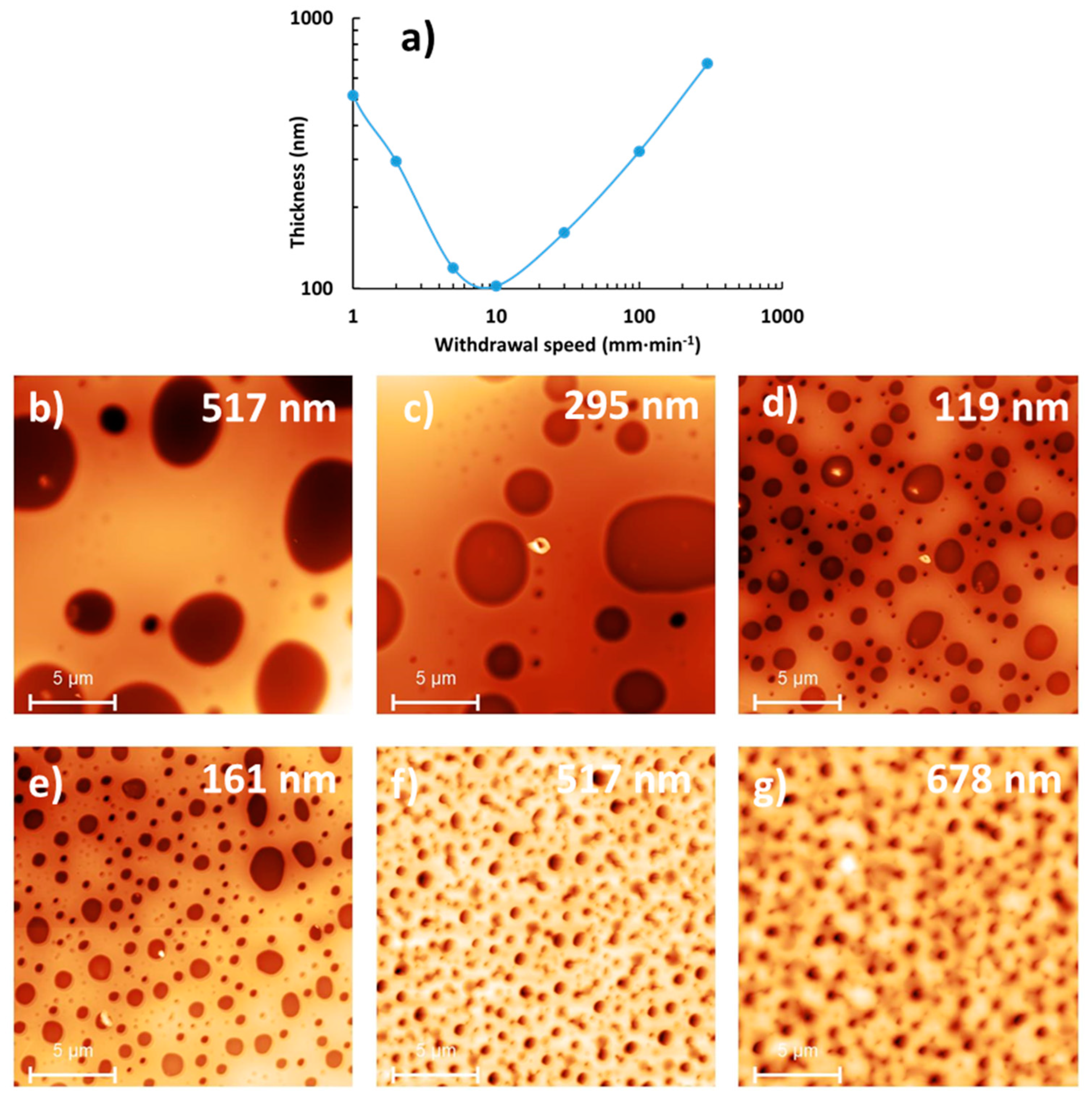
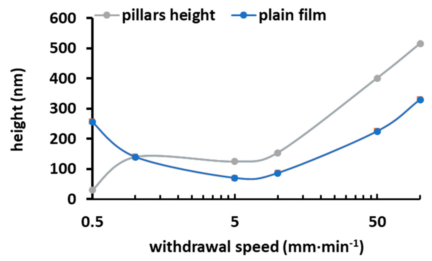
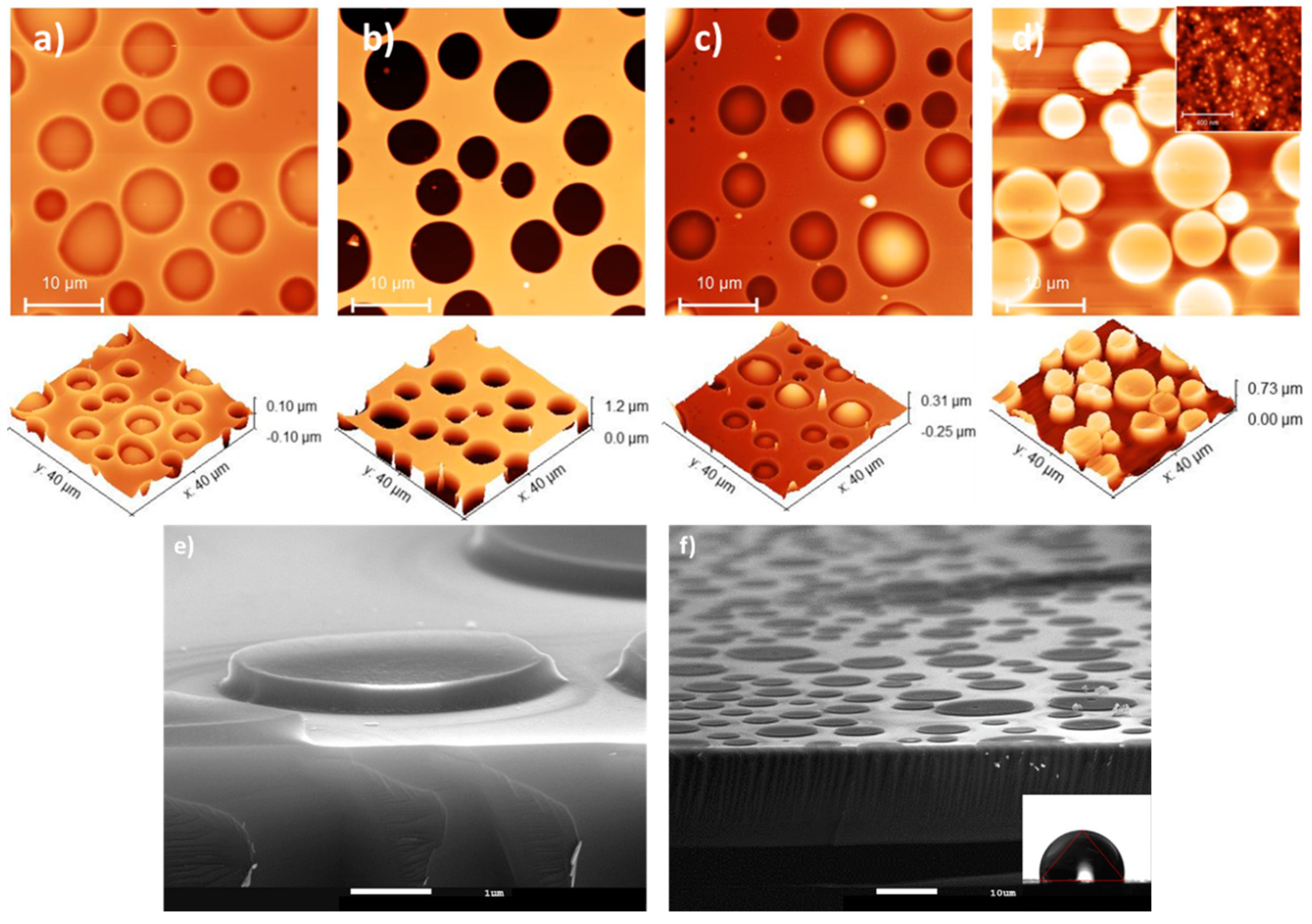
3.3. Micrometric Surface Structuring of PVP Composite Film
4. Conclusions
Supplementary Materials
Author Contributions
Funding
Institutional Review Board Statement
Informed Consent Statement
Data Availability Statement
Acknowledgments
Conflicts of Interest
References
- Zeng, Q.; Zhou, H.; Huang, J.; Guo, Z. Review on the recent development of durable superhydrophobic materials for practical applications. Nanoscale 2021, 13, 11734–11764. [Google Scholar] [CrossRef]
- Ahmad, D.; van den Boogaert, I.; Miller, J.; Presswell, R.; Jouhara, H. Hydrophilic and hydrophobic materials and their applications. Energy Sources A Recovery Util. Environ. Eff. 2018, 40, 2686–2725. [Google Scholar] [CrossRef]
- Alawajji, R.A.; Kannarpady, G.K.; Biris, A.S. Fabrication of transparent superhydrophobic polytetrafluoroethylene coating. Appl. Surf. Sci. 2018, 444, 208–215. [Google Scholar] [CrossRef]
- Maghsoudi, K.; Vazirinasab, E.; Momen, G. Advances in the fabrication of superhydrophobic polymeric surfaces by polymer molding processes. Ind. Eng. Chem. Res. 2020, 59, 9343–9363. [Google Scholar] [CrossRef]
- Jiang, C.; Zhang, Y.; Wang, Q.; Wang, T. Superhydrophobic polyurethane and silica nanoparticles coating with high trans-parency and fluorescence. J. Appl. Polym. Sci. 2013, 129, 2959–2965. [Google Scholar] [CrossRef]
- Wen, G.; Guo, Z.; Liu, W. Biomimetic polymeric superhydrophobic surfaces and nanostructures: From fabrication to applications. Nanoscale 2017, 9, 3338–3366. [Google Scholar] [CrossRef] [PubMed]
- Yilbas, S.; Khaled, M.; Abu-Dheir, N.; Al-Aqeeli, N.; Said, S.A.M.; Ahmed, A.O.M.; Varanasi, K.K.; Toumi, Y.K. Wetting and other physical characteristics of polycarbonate surface textured using laser ablation. Appl. Surf. Sci. 2014, 320, 21–29. [Google Scholar] [CrossRef]
- Gong, X.; Zhang, L.; He, S.; Jiang, S.; Wang, W.; Wu, Y. Rewritable superhydrophobic coatings fabricated using water-soluble polyvinyl alcohol. Mater. Des. 2020, 196, 109112. [Google Scholar] [CrossRef]
- Bai, C.; Hu, C.; Ni, P.; Zhang, X.; Zhang, W.; Zhang, S.; Tang, J.; Li, T.; Li, Y. Fabrication of robust, superhydropho-bic-superoleophilic PVA sponge by one-pot hydrothermal method for oil-water separation. Surf. Interfaces 2023, 37, 102679. [Google Scholar] [CrossRef]
- Oh, J.-H.; Ko, T.-J.; Moon, M.-W.; Park, C. Hee Nanostructured superhydrophobic silk fabric fabricated using the ion beam method. RSC Adv. 2014, 4, 38966–38973. [Google Scholar] [CrossRef]
- Adithyavairavan, M.; Subbiah, S. A morphological study on direct polymer cast micro-textured hydrophobic surfaces. Surf. Coat. Technol. 2011, 205, 4764–4770. [Google Scholar] [CrossRef]
- Erbil, H.Y.; Demirel, A.L.; Avci, Y.; Mert, O. Transformation of a simple plastic into a superhydrophobic surface. Science 2003, 299, 1377–1380. [Google Scholar] [CrossRef] [PubMed]
- Li, X.; Chen, G.; Ma, Y.; Feng, Y.; Zhao, H.; Jiang, L.; Wang, F. Preparation of a super-hydrophobic poly(vinyl chloride) sur-face via solvent-nonsolvent coating. Polym. J. 2006, 47, 506–509. [Google Scholar] [CrossRef]
- Zhang, R.; Wei, J.; Tian, N.; Liang, W.; Zhang, J. Facile preparation of robust superamphiphobic coatings on complex substrates via nonsolvent-induced phase separation. ACS Appl. Mater. Interfaces 2022, 14, 49047–49058. [Google Scholar] [CrossRef] [PubMed]
- Rioboo, R.; Demnati, I.; Ali, M.A.; Sevkan, R.; De Coninck, J. Superhydrophobicity of composite surfaces created from polymer blends. J. Colloid Interface Sci. 2020, 560, 596–605. [Google Scholar] [CrossRef] [PubMed]
- Bormashenko, E.; Stein, T.; Whyman, G.; Bormashenko, Y.; Pogreb, R. Wetting Properties of the Multiscaled Nanostructured Polymer and Metallic Superhydrophobic Surfaces. Langmuir 2006, 22, 9982–9985. [Google Scholar] [CrossRef]
- Jung, Y.C.; Bhushan, B. Mechanically Durable Carbon Nanotube–Composite Hierarchical Structures with Superhydrophobicity, Self-Cleaning, and Low-Drag. ACS Nano 2009, 3, 4155–4163. [Google Scholar] [CrossRef]
- Yilgor, I.; Bilgin, S.; Isik, M.; Yilgor, E. Tunable wetting of polymer surfaces. Langmuir 2012, 28, 14808–14814. [Google Scholar] [CrossRef]
- Yilgor, I.; Bilgin, S.; Isik, M.; Yilgor, E. Facile preparation of superhydrophobic polymer surfaces. Polymer 2012, 53, 1180–1188. [Google Scholar] [CrossRef]
- Su, H.; Yang, J. Design and preparation of multiple silica particles and study on superhydrophobic modified epoxy resin. J. Polym. Res. 2023, 30, 238. [Google Scholar] [CrossRef]
- Yousefi, E.; Ghadimi, M.R.; Amirpoor, S.; Dolati, A. Preparation of new superhydrophobic and highly oleophobic polyure-thane coating with enhanced mechanical durability. Appl. Surf. Sci. 2018, 454, 201–209. [Google Scholar] [CrossRef]
- Sunny, S.; Vogel, N.; Howell, C.; Vu, T.L.; Aizenberg, J. Lubricant-Infused Nanoparticulate Coatings Assembled by Lay-er-by-Layer Deposition. Adv. Funct. Mater. 2014, 24, 6658–6667. [Google Scholar] [CrossRef]
- Ghamarpoor, R.; Jamshidi, M. Preparation of Superhydrophobic/Superoleophilic nitrile rubber (NBR) nanocomposites contained silanized nano silica for efficient oil/water separation. Sep. Purif. Technol. 2022, 291, 120854. [Google Scholar] [CrossRef]
- Söz, C.K.; Yilgör, E.; Yilgör, I. Influence of the average surface roughness on the formation of superhydrophobic polymer surfaces through spin-coating with hydrophobic fumed silica. Polymer 2015, 62, 118–128. [Google Scholar] [CrossRef]
- Seyfi, J.; Hejazi, I.; Jafari, S.H.; Khonakdar, H.A.; Simon, F. Enhanced hydrophobicity of polyurethane via non-solvent in-duced surface aggregation of silica nanoparticles. J. Colloid Interface Sci. 2016, 478, 117–126. [Google Scholar] [CrossRef] [PubMed]
- Khakbaz, M.; Hejazi, I.; Seyfi, J.; Jafari, S.-H.; Khonakdar, H.A.; Davachi, S.M. A novel method to control hydrolytic degra-dation of nanocomposite biocompatible materials via imparting superhydrophobicity. Appl. Surf. Sci. 2015, 357, 880–886. [Google Scholar] [CrossRef]
- Zhu, Y.; Pei, L.; Ambreen, J.; He, C.; Ngai, T. Facile Preparation of a Fluorine-Free, Robust, Superhydrophobic Coating through Dip Coating Combined with Non-Solvent Induced Phase Separation (Dip-Coating-NIPS) Method. Macromol. Chem. Phys. 2020, 221, 2000023. [Google Scholar] [CrossRef]
- Ghutepatil, P.; Khot, V.M.; Salunkhe, A.B. Design of monodispersed PVP functionalized biocompatible manganese ferrite nanoparticles for hyperthermia application. Mater. Today Proc. 2022, 62, 5341–5346. [Google Scholar] [CrossRef]
- Kurakula, M.; Rao, G.K. Moving polyvinyl pyrrolidone electrospun nanofibers and bioprinted scaffolds toward multidisciplinary biomedical applications. Eur. Polym. J. 2020, 136, 109919. [Google Scholar] [CrossRef]
- Harinkhere, D.; Karma, N.; Choudhary, K.K.; Kaurav, N. Structural and optical properties of PPO/PVP blended polymer film. Mater. Today Proc. 2022, 54, 620–623. [Google Scholar] [CrossRef]
- Kamarudin, D.; Hashim, N.A.; Ong, B.H.; Che Hassan, C.R.; Abdul Manaf, N. Synthesis of silver nanoparticles stabilised by pvp for polymeric membrane application: A comparative study. Mater. Technol. 2022, 37, 289–301. [Google Scholar] [CrossRef]
- Jebali, S.; Vayer, M.; Belal, K.; Mahut, F.; Sinturel, C. Dip coating deposition of nanocomposite thin films based on water-soluble polymer and silica nanoparticles. Colloids Surf. A Physicochem. Eng. Asp. 2024, 680, 132688. [Google Scholar] [CrossRef]
- Fechine, G.J.M.; Barros, J.A.G.; Catalani, L.H. Poly(N-vinyl-2-pyrrolidone) hydrogel production by ultraviolet radiation: New methodologies to accelerate crosslinking. Polymer 2004, 45, 4705–4709. [Google Scholar] [CrossRef]
- Tajik, F.; Eslahi, N.; Rashidi, A.; Rad, M.M. Hybrid antibacterial hydrogels based on PVP and keratin incorporated with lavender extract. J. Polym. Res. 2021, 28, 316. [Google Scholar] [CrossRef]
- Riga, E.K.; Saar, J.S.; Erath, R.; Hechenbichler, M.; Lienkamp, K. On the Limits of Benzophenone as Cross-Linker for Sur-face-Attached Polymer Hydrogels. Polymer 2017, 9, 686. [Google Scholar] [CrossRef] [PubMed]
- Christensen, S.K.; Chiappelli, M.C.; Hayward, R.C. Gelation of Copolymers with Pendent Benzophenone Pho-to-Cross-Linkers. Macromolecules 2012, 45, 5237–5246. [Google Scholar] [CrossRef]
- Rasband, W.S. ImageJ U.S. National Institutes of Health, Bethesda, Maryland, USA. 1997–2018. Available online: https://imagej.nih.gov/ij/ (accessed on 22 January 2024).
- Grube, S.; Siegmann, K.; Hirayama, M. A moisture-absorbing and abrasion-resistant transparent coating on polystyrene. J. Coat. Technol. Res. 2015, 12, 669–680. [Google Scholar] [CrossRef]
- Mirek, A.; Grzeczkowicz, M.; Belaid, H.; Bartkowiak, A.; Barranger, F.; Abid, M.; Wasyłeczko, M.; Pogorielov, M.; Bechelany, M.; Lewińska, D. Electrospun UV-cross-linked polyvinylpyrrolidone fibers modified with polycaprolactone/polyethersulfone microspheres for drug delivery. Biomater. Adv. 2023, 147, 213330. [Google Scholar] [CrossRef]
- Zhu, X.; Chen, P.L.W.; Dong, J. Studies of UV crosslinked poly(N-vinylpyrrolidone) hydrogels by FTIR, Raman and solid state NMR spectroscopies. Polymer 2010, 51, 3054–3063. [Google Scholar] [CrossRef]
- Zhang, Q.G.; Hu, W.W.; Zhu, A.M.; Liu, Q.L. UV-crosslinked chitosan /polyvinylpyrrolidone blended membranes for pervaporation. RSC Adv. 2013, 3, 1855–1861. [Google Scholar] [CrossRef]
- Maciejewska, B.M.; Wychowaniec, J.K.; Woźniak-Budych, M.; Popenda, Ł.; Warowicka, A.; Golba, K.; Litowczenko, J.; Fojud, Z.; Wereszczyńska, B.; Jurga, S. UV cross-linked polyvinylpyrrolidone electrospun fibres as antibacterial surfaces. Sci. Technol. Adv. Mater. 2019, 20, 979–991. [Google Scholar] [CrossRef] [PubMed]
- Sun, M.; Qiu, H.; Su, C.; Shi, X.; Wang, Z.; Ye, Y.; Zhu, Y. Solvent-Free Graft-From Polymerization of Polyvinylpyrrolidone Imparting Ultralow Bacterial Fouling and Improved Biocompatibility. ACS Appl. Bio. Mater. 2019, 2, 3983–3991. [Google Scholar] [CrossRef] [PubMed]
- Slavov, S.V.; Sanger, A.R.; Chuang, K.T. Mechanism of Silation of Silica with Hexamethyldisilazane. J. Phys. Chem. B 2000, 104, 983–989. [Google Scholar] [CrossRef]
- Rao, A.V.; Pajonk, G.M.; Bhagat, S.D.; Barboux, P. Comparative studies on the surface chemical modification of silica aero-gels based on various organosilane compounds of the type RnSiX4-n. J. Non-Cryst. Solids 2004, 350, 216–223. [Google Scholar] [CrossRef]
- Qin, W.; Vautard, F.; Askeland, P.; Yu, J.; Drzal, L.T. Incorporation of Silicon Dioxide Nanoparticles at the Carbon Fi-ber-Epoxy Matrix Interphase and Its Effect on Composite Mechanical Properties. Polym. Compos. 2017, 38, 1474–1482. [Google Scholar] [CrossRef]
- O’Mahony, T.F.; Morris, M.A. Hydroxylation methods for mesoporous silica and their impact on surface functionalisation. Micropor. Mesopor. Mat. 2021, 317, 110989. [Google Scholar] [CrossRef]
- Nishino, T.; Meguro, M.; Nakamae, K.; Matsushita, M.; Ueda, Y. The Lowest Surface Free Energy Based on -CF3 Alignment. Langmuir 1999, 15, 4321–4323. [Google Scholar] [CrossRef]
- Tutejaa, A.; Choib, W.; Mabryc, J.M.; McKinley, G.H.; Cohena, R.E. Robust omniphobic surfaces. Proc. Natl. Acad. Sci. USA 2008, 105, 18200–18205. [Google Scholar] [CrossRef]
- Murakami, D.; Jinnai, H.; Takahara, A. Wetting Transition from the Cassie−Baxter State to the Wenzel State on Textured Polymer Surfaces. Langmuir 2014, 30, 2061–2067. [Google Scholar] [CrossRef]
- Roach, P.; Shirtcliffe, N.J.; Newton, M.I. Progess in superhydrophobic surface development. Soft Matter 2008, 4, 224–240. [Google Scholar] [CrossRef]
- Wenzel, R.N. Resistance of solid surfaces to wetting by water. Ind. Eng. Chem. 1936, 28, 7. [Google Scholar] [CrossRef]
- Cassie, A.B.D.; Baxter, S. Wettability of Porous Surfaces. Trans. Faraday Soc. 1944, 40, 546–551. [Google Scholar] [CrossRef]
- Moulinet, S.; Bartolo, D. Life and death of a fakir droplet: Impalement transitions on superhydrophobic surfaces. Eur. Phys. J. E 2007, 24, 251–260. [Google Scholar] [CrossRef]
- Elbourne, A.; Crawford, R.J.; Ivanova, E.P. Nano-structured antimicrobial surfaces: From nature to synthetic analogues. J. Colloid Interface Sci. 2017, 508, 603–616. [Google Scholar] [CrossRef]
- Söz, C.K.; Yilgör, E.; Yilgör, I. Influence of the coating method on the formation of superhydrophobic silicone–urea surfaces modified with fumed silica nanoparticles. Prog. Org. Coat. 2015, 84, 143–152. [Google Scholar] [CrossRef]
- Zheng, Q.; Lü, C. Size effects of surface roughness to superhydrophobicity. Procedia IUTAM 2014, 10, 462–475. [Google Scholar] [CrossRef]
- Vital, A.; Vayer, M.; Tillocher, T.; Dussart, R.; Boufnichel, M.; Sinturel, C. Morphology control in PS/PLA blends films by dip-coating deposition. Appl. Surf. Sci. 2017, 393, 127–133. [Google Scholar] [CrossRef]
- Vital, A.; Vayer, M.; Sinturel, C.; Tillocher, T.; Lefaucheux, P.; Dussart, R. Polymer masks for structured surface and plasma etching. Appl. Surf. Sci. 2015, 332, 237–246. [Google Scholar] [CrossRef]
- Guo, H.; Yang, J.; Zhao, W.; Xu, T.; Lin, C.; Zhang, J.; Zhang, L. Direct formation of amphiphilic crosslinked networks based on PVP as a marine anti-biofouling coating. Chem. Eng. J. 2019, 374, 1353. [Google Scholar] [CrossRef]
- Verho, T.; Bower, C.; Andrew, P.; Franssila, S.; Ikkala, O.; Ras, R.H.A. Mechanically Durable Superhydrophobic Surfaces. Adv. Mater. 2011, 23, 673. [Google Scholar] [CrossRef] [PubMed]

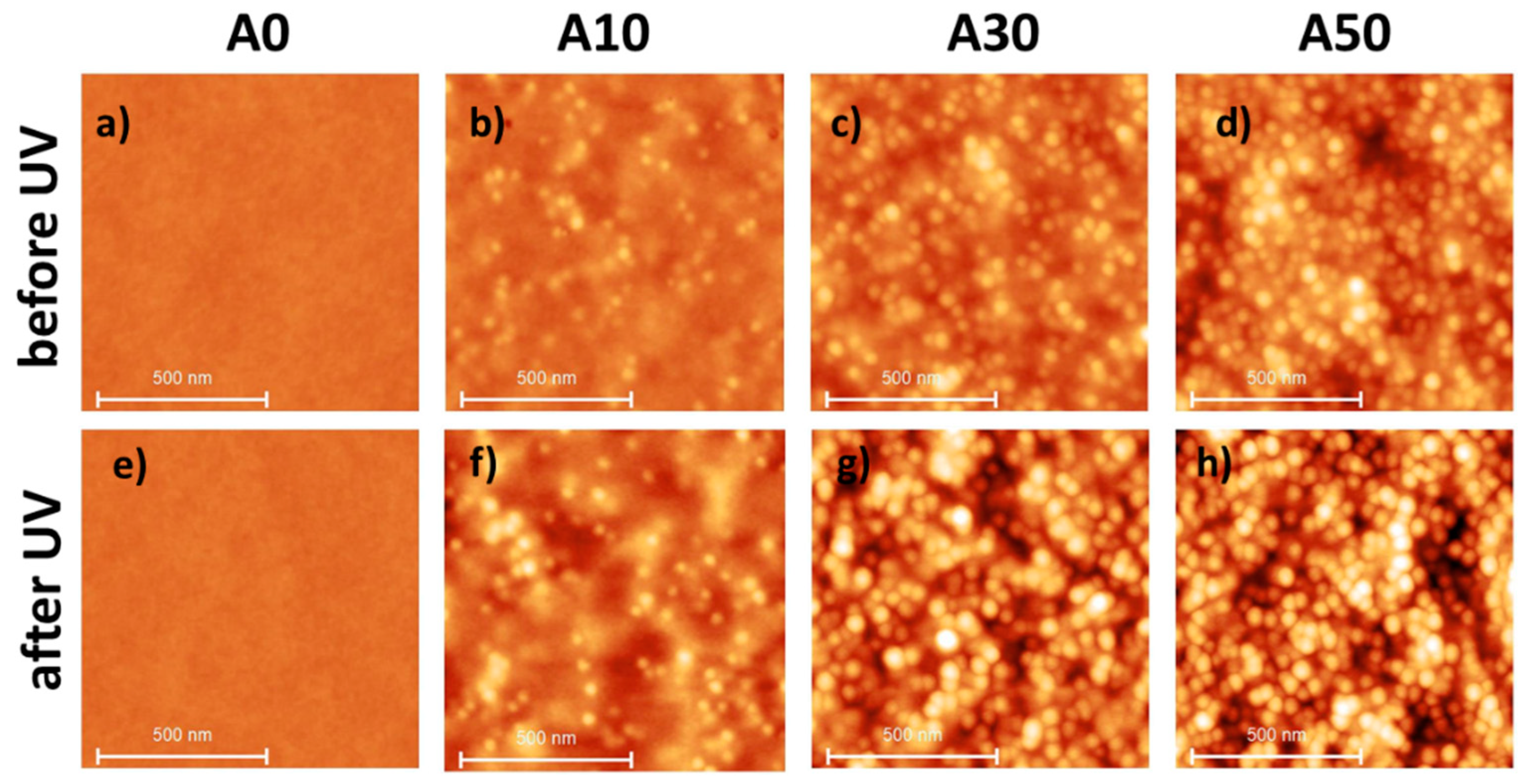
| A0 | A10 | A30 | A50 | |
|---|---|---|---|---|
| Nominal NP:PVP wt. proportion in suspension | 0:100 | 10:100 | 30:100 | 50:100 |
| % vol. of PVP + NP (mL·mL−1) in suspension | 3.83 | 3.82 | 3.78 | 3.74 |
| Conc. of PVP + NP (g·mL−1) in suspension | 0.046 | 0.046 | 0.048 | 0.050 |
| % vol. of NP (mL·mL−1) in the dry film | 0 | 5.4 | 15.2 | 20.0 |
| A0 | A10 | A30 | A50 | ||
|---|---|---|---|---|---|
| After deposition | Thickness (nm) | 100 ± 5 | 100 ± 5 | 105 ± 5 | 125 ± 5 |
| Roughness Rq 1 (nm) | 0.2 ± 0.1 | 1.2 ± 0.2 | 2.0 ± 0.2 | 2.2 ± 0.2 | |
| UV irradiation | Thickness (nm) | 91 ± 5 | 90 ± 5 | 90 ± 5 | 76 ± 5 |
| Roughness Rq 1 (nm) | 0.2 ± 0.1 | 1.3 ± 0.2 | 2.8 ± 0.2 | 4.1 ± 0.2 | |
| WCA (°) 2,3 | 27 ± 4 | 29 ± 4 | 20 ± 4 | 27 ± 3 | |
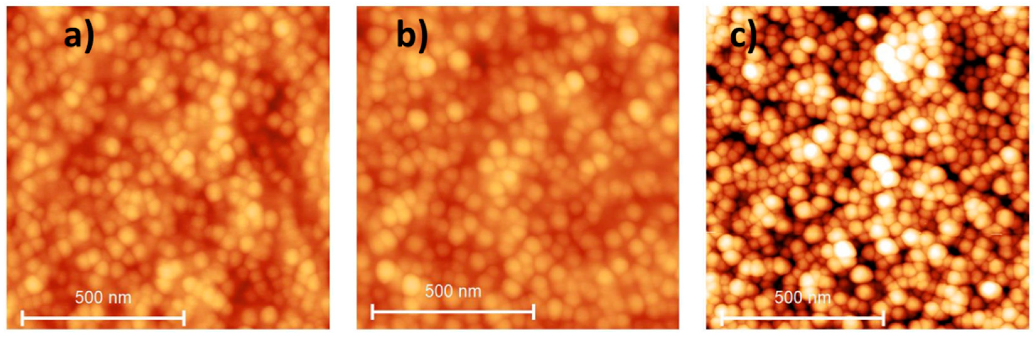
| Protocol A 4 | WCA (°) 2,3 | 34 ± 3 | 41 ± 3 | 43 ± 3 | 47 ± 2 |
| Protocol B | Thickness (nm) | 79 ± 5 | 79 ± 5 | 68 ± 5 | 65 ± 5 |
| Roughness Rq 1 (nm) | 0.2 ± 0.1 | 1.4 ± 0.2 | 6.4 ± 0.2 | 8.7 ± 0.2 | |
| WCA (°) 2,3 | 35 ± 4 | 60 ± 4 | 80 ± 4 | 90 ± 4 |
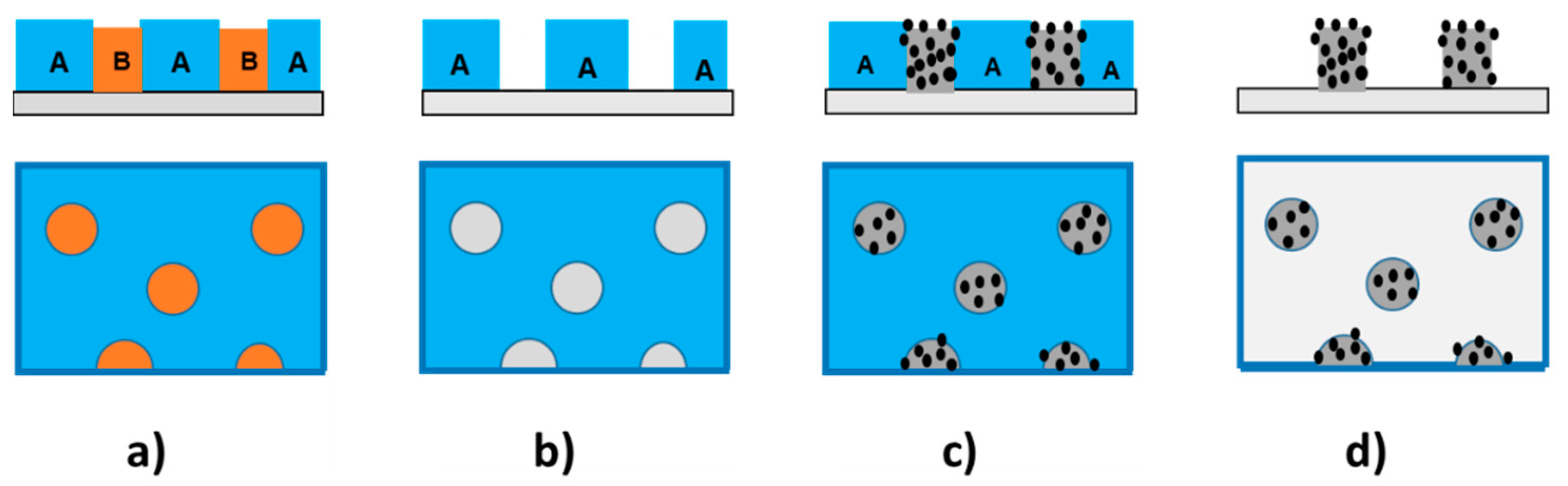
| A0/Pillars | A10/Pillars | A50/Pillars | |
|---|---|---|---|
| Treatment A | 81 (34) | 96 (41) | 93 (54) |
| Treatment B | 80 (34) | 110 (60) | 110 (90) |
Disclaimer/Publisher’s Note: The statements, opinions and data contained in all publications are solely those of the individual author(s) and contributor(s) and not of MDPI and/or the editor(s). MDPI and/or the editor(s) disclaim responsibility for any injury to people or property resulting from any ideas, methods, instructions or products referred to in the content. |
© 2024 by the authors. Licensee MDPI, Basel, Switzerland. This article is an open access article distributed under the terms and conditions of the Creative Commons Attribution (CC BY) license (https://creativecommons.org/licenses/by/4.0/).
Share and Cite
Jebali, S.; Vayer, M.; Belal, K.; Sinturel, C. Engineered Nanocomposite Coatings: From Water-Soluble Polymer to Advanced Hydrophobic Performances. Materials 2024, 17, 574. https://doi.org/10.3390/ma17030574
Jebali S, Vayer M, Belal K, Sinturel C. Engineered Nanocomposite Coatings: From Water-Soluble Polymer to Advanced Hydrophobic Performances. Materials. 2024; 17(3):574. https://doi.org/10.3390/ma17030574
Chicago/Turabian StyleJebali, Syrine, Marylène Vayer, Khaled Belal, and Christophe Sinturel. 2024. "Engineered Nanocomposite Coatings: From Water-Soluble Polymer to Advanced Hydrophobic Performances" Materials 17, no. 3: 574. https://doi.org/10.3390/ma17030574