
Self-Healing of Cracks in Cementitious Materials as a Method of Improving the Durability of Pre-Stressed Concrete Railway Sleepers


Abstract
:1. Introduction
1.1. Factors Influencing the Durability of Pre-Stressed Concrete Railway Sleepers
1.2. Methods Used in the Self-Healing of Cementitious Materials
1.3. Purpose and Scope of Research
2. Materials and Methods
2.1. Materials
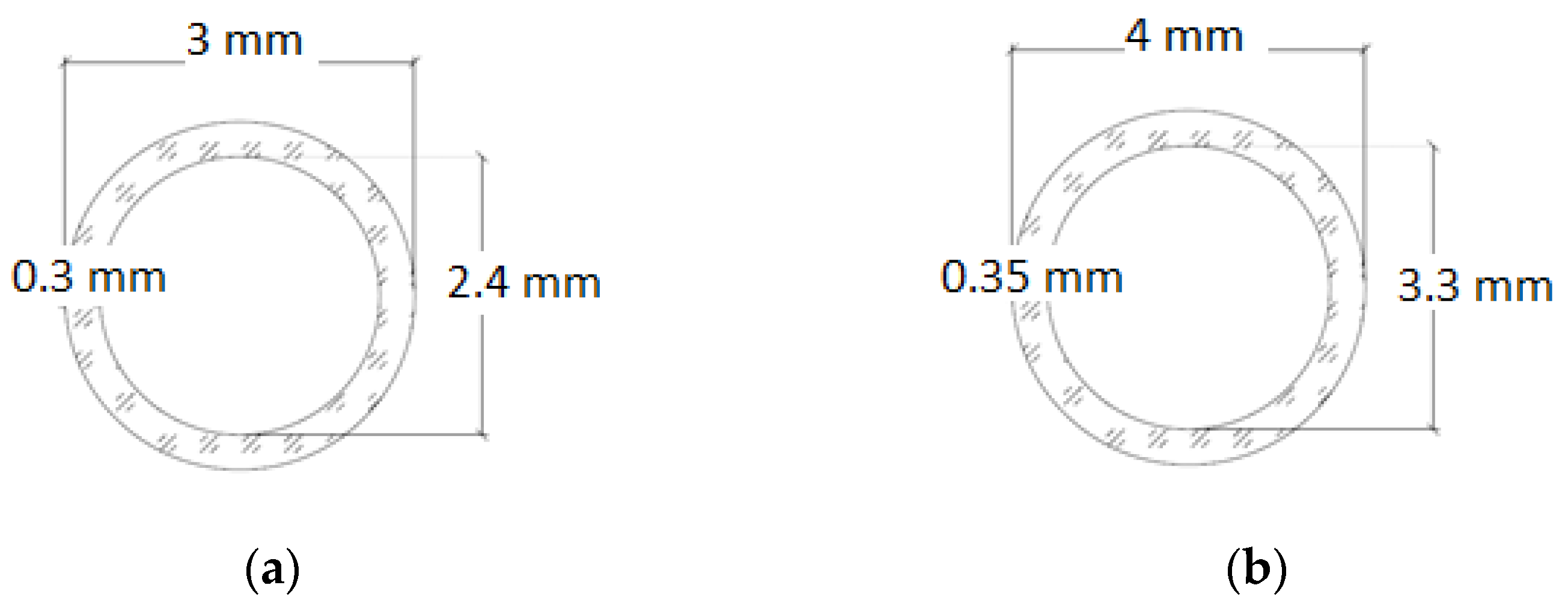
2.1.1. Glass Tubes
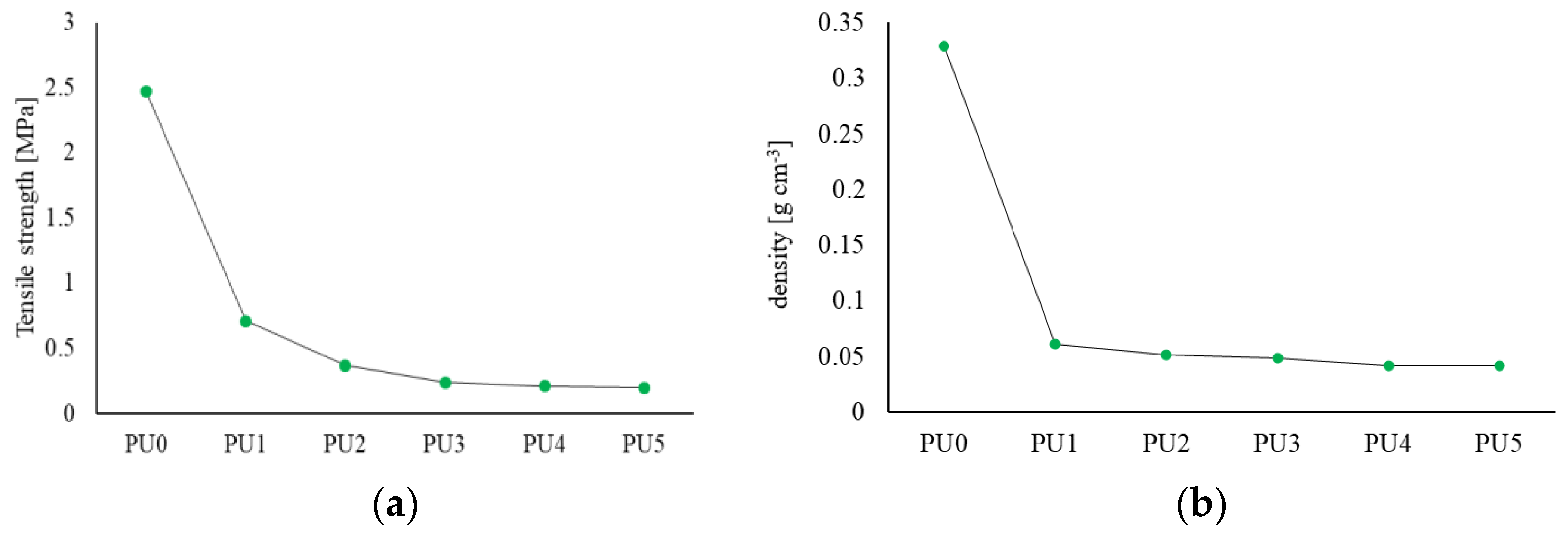
2.1.2. Healing Agent
2.1.3. Cement Mortar
2.1.4. Concrete
2.2. Methods
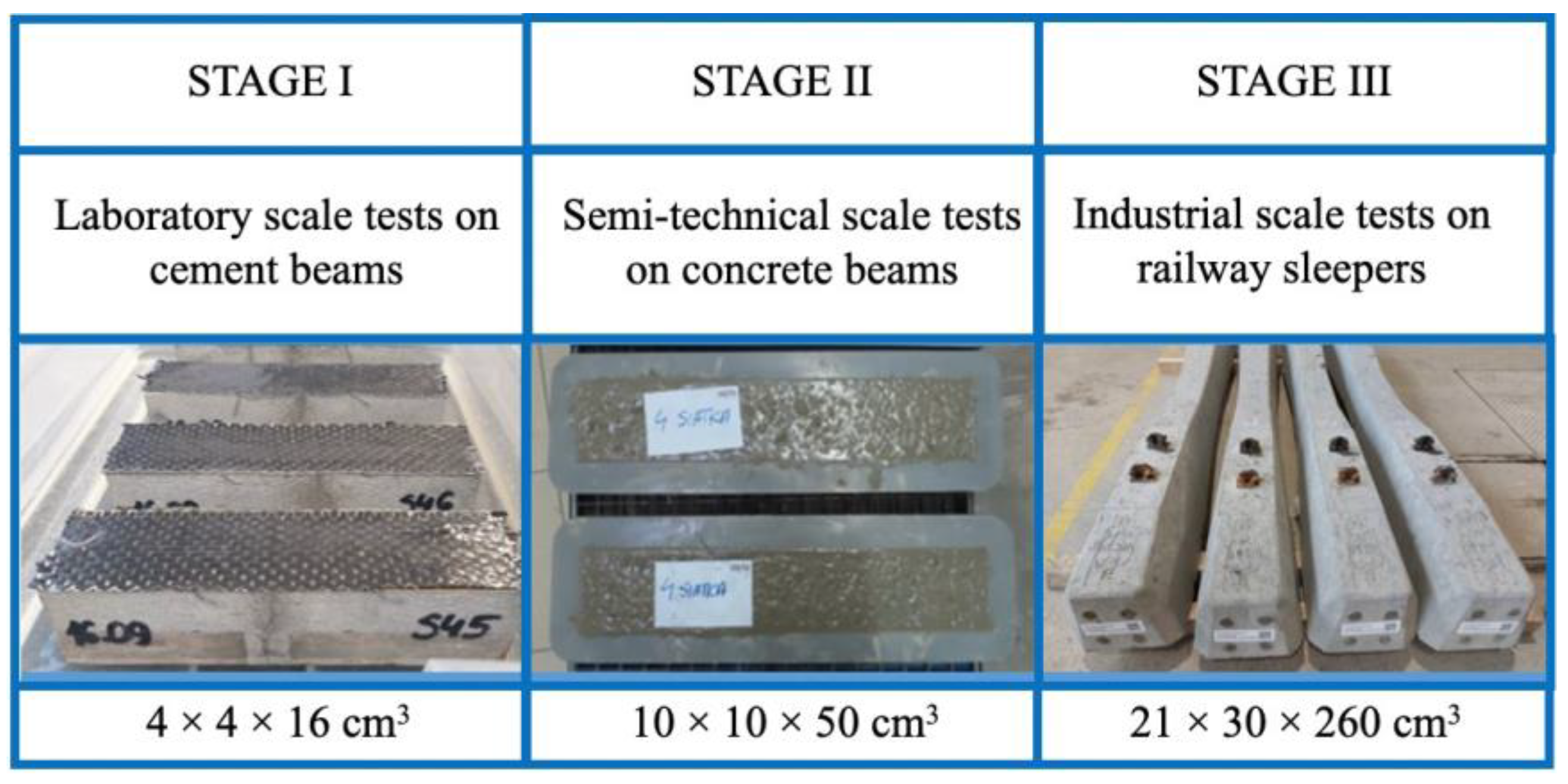
2.2.1. Test Methods for Mortars on a Laboratory Scale
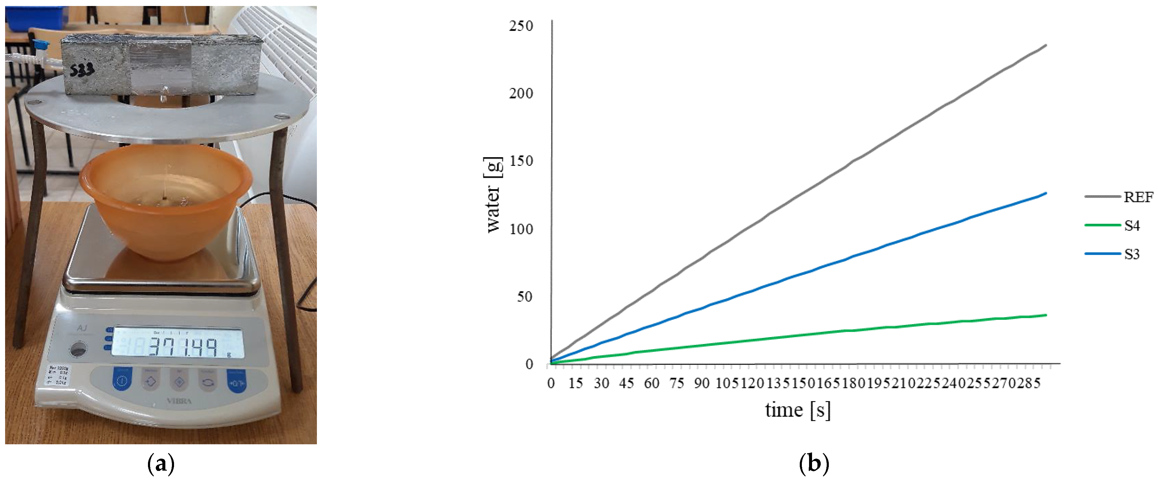
Water Permeability Test
Water Absorption Test
Macroscopic Observations
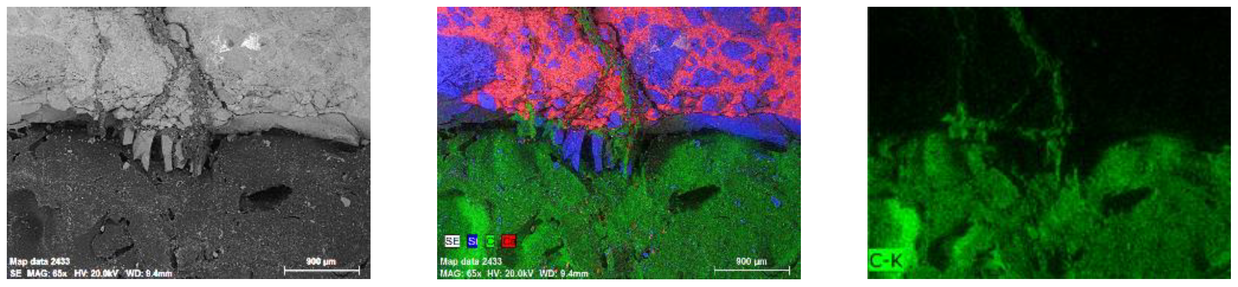
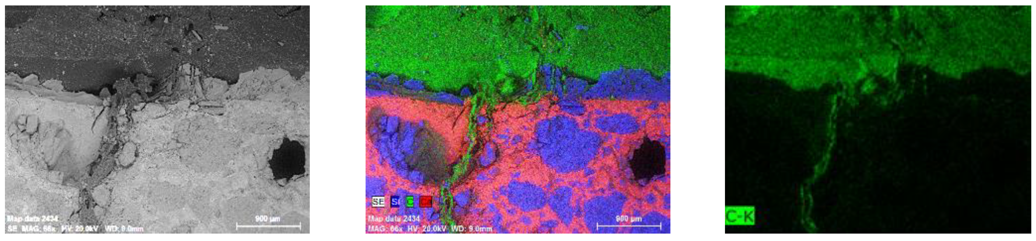
Observations in a Scanning Microscope
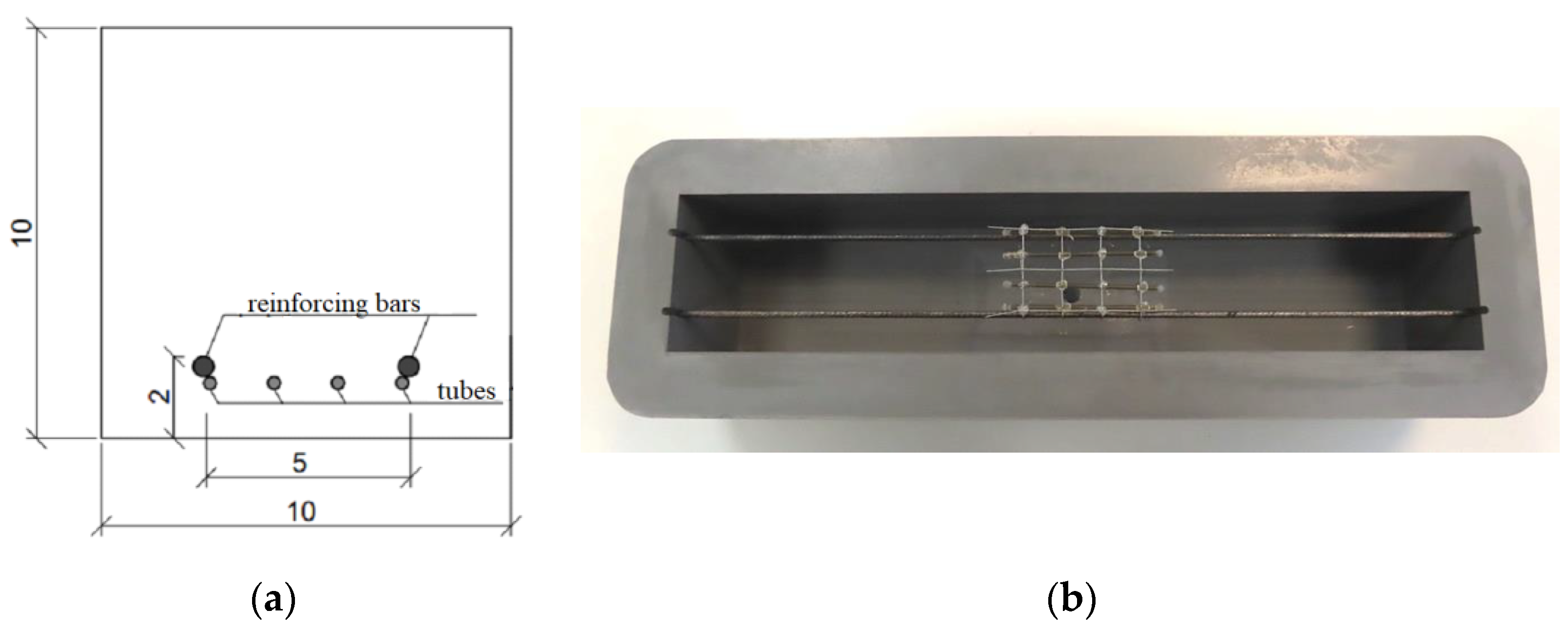
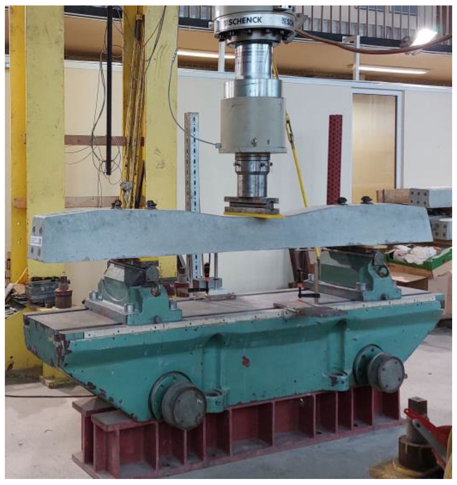
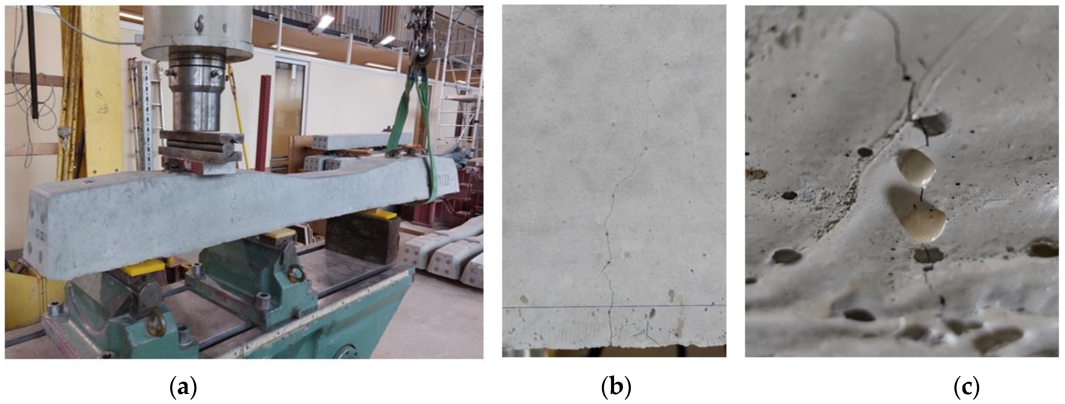
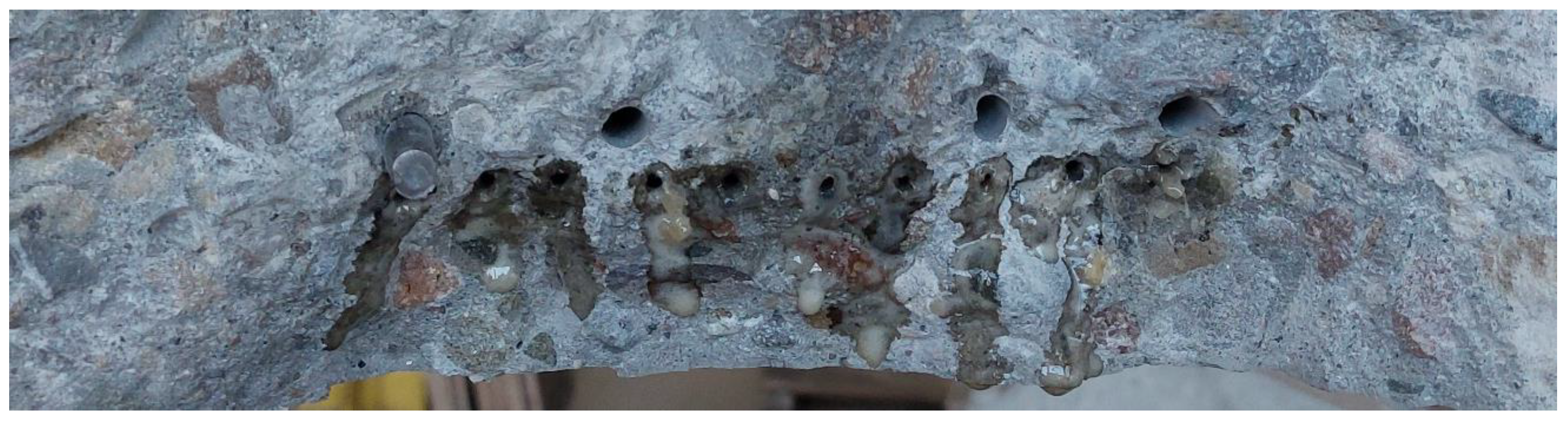
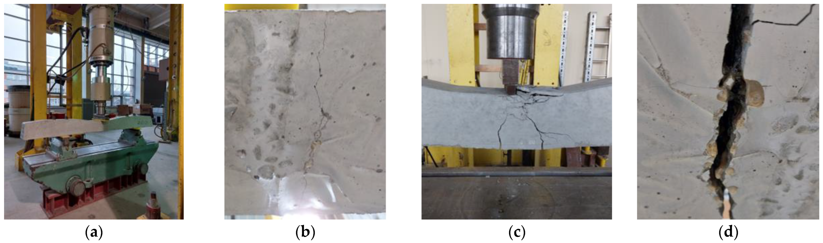
2.2.2. Test Methods for Concrete Beams on a Semi-Technical Scale
- In stage 1, testing the installation of the tubes directly on the reinforcement was performed; for this purpose, one beam with tubes S3 and S4 was made. These beams were bent 7 days after casting.
- In stage 2, testing the installation of the tubes on the steel mesh and checking the ability of the PU to flow out of the carriers was performed; for this purpose, two beams with S3 and S4 tubes were made. These beams were bent 28 days after casting.
- The method of installing the tubes evolved during the tests. Initially, in stage 1, the tubes were attached to the rods using thin wires, but this did not give the expected result, and the tubes moved when the mould was moved or during vibration, so this method of assembly was abandoned. Finally, in stage 2, the tubes were attached to a square steel mesh (25 × 25 mm2) made of wire with a diameter of 0.7 mm. Then the mesh with tubes was attached to steel rods, which ensured the stability of the system.
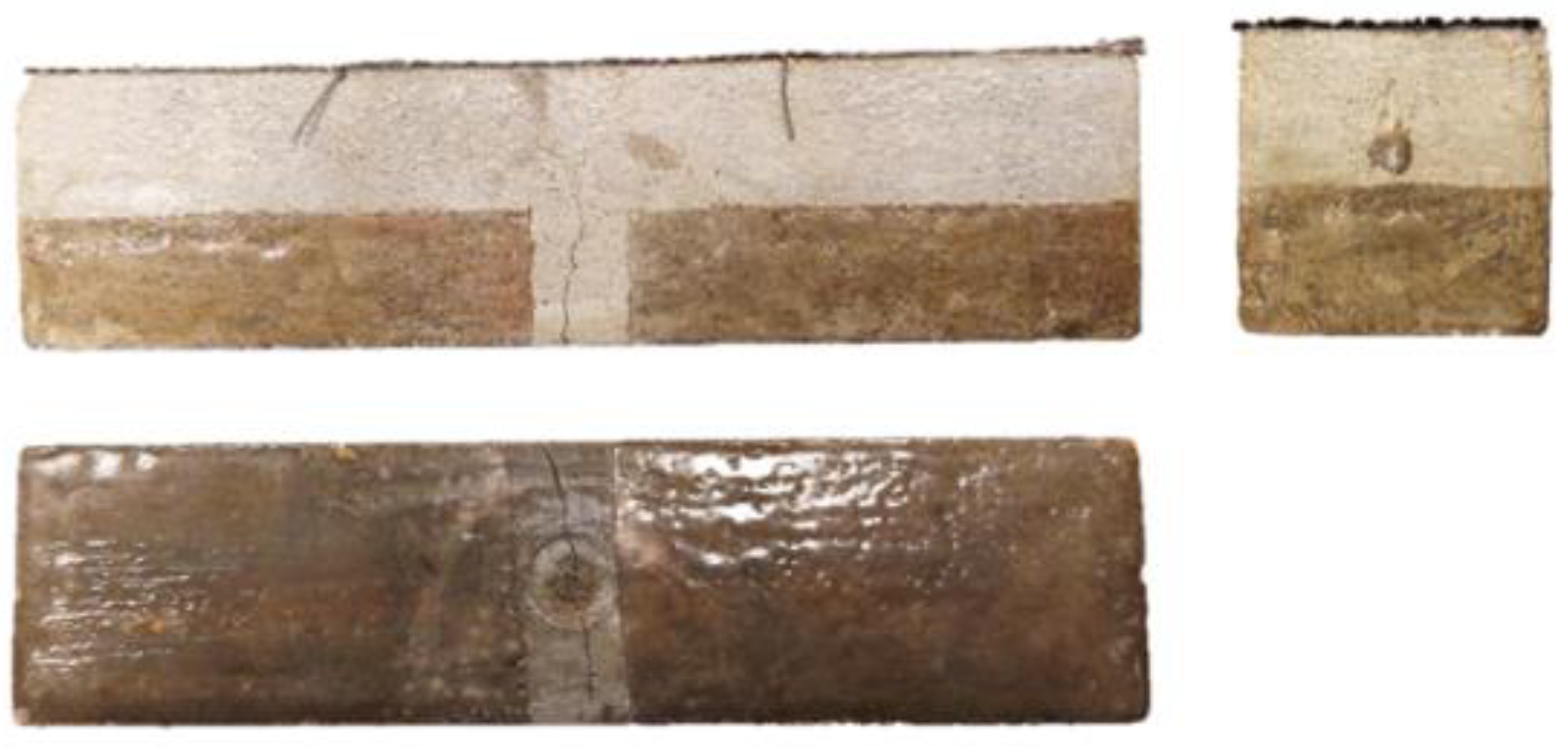
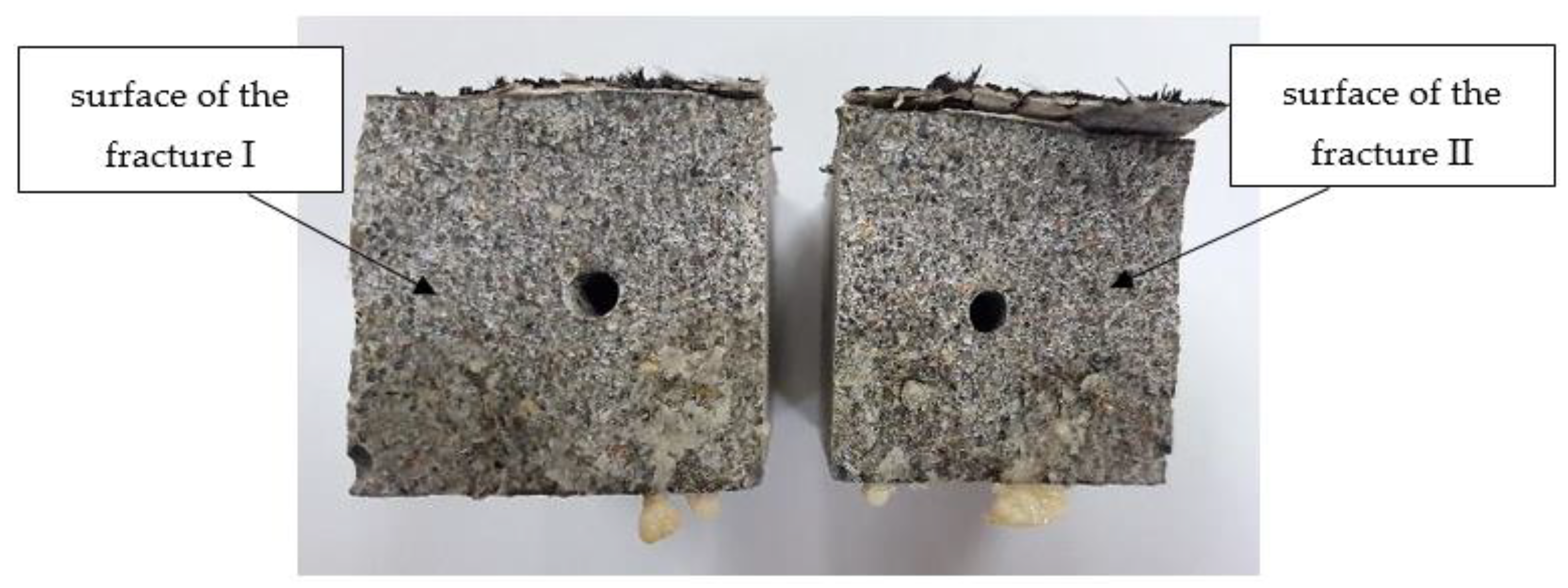
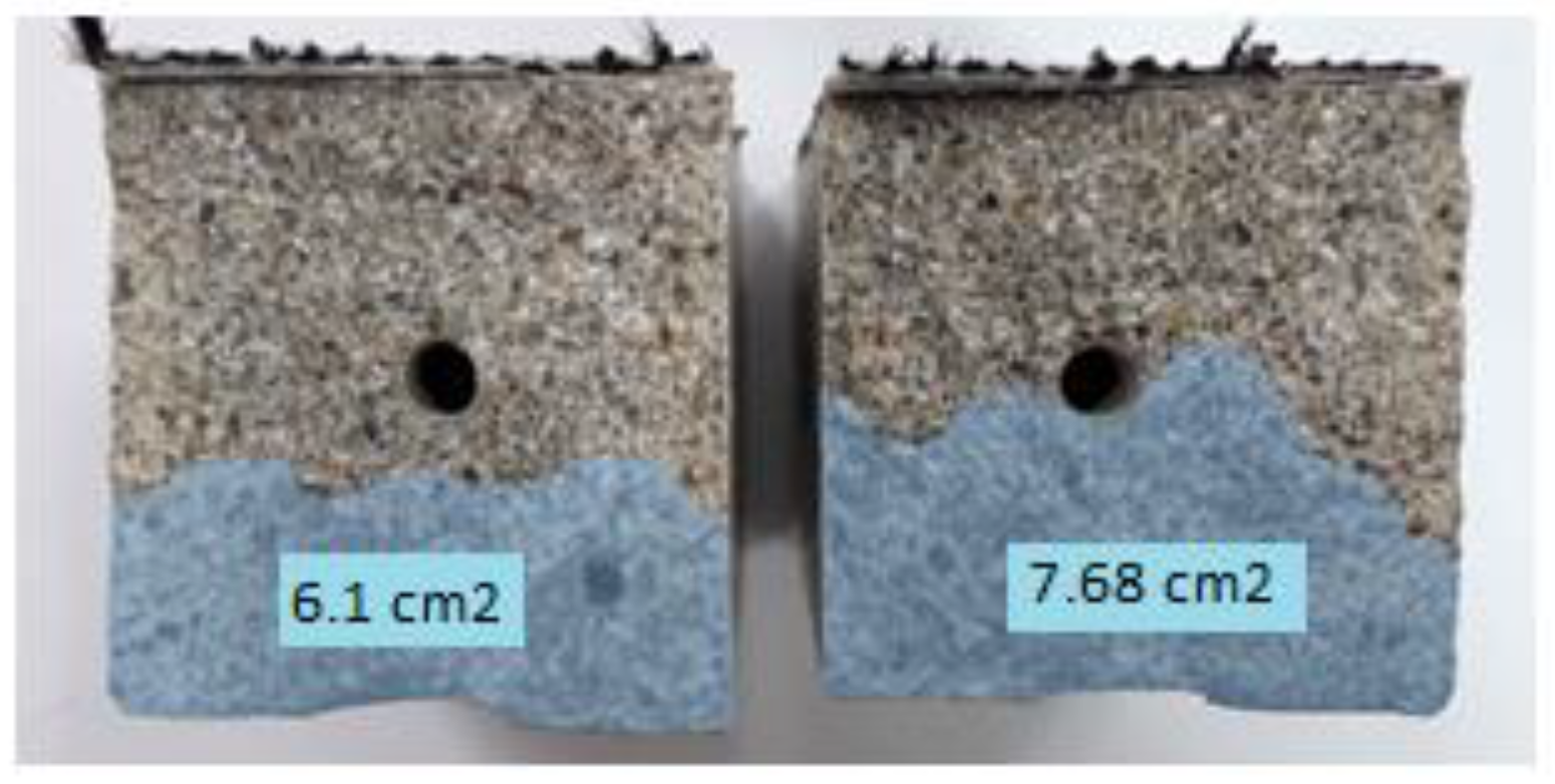
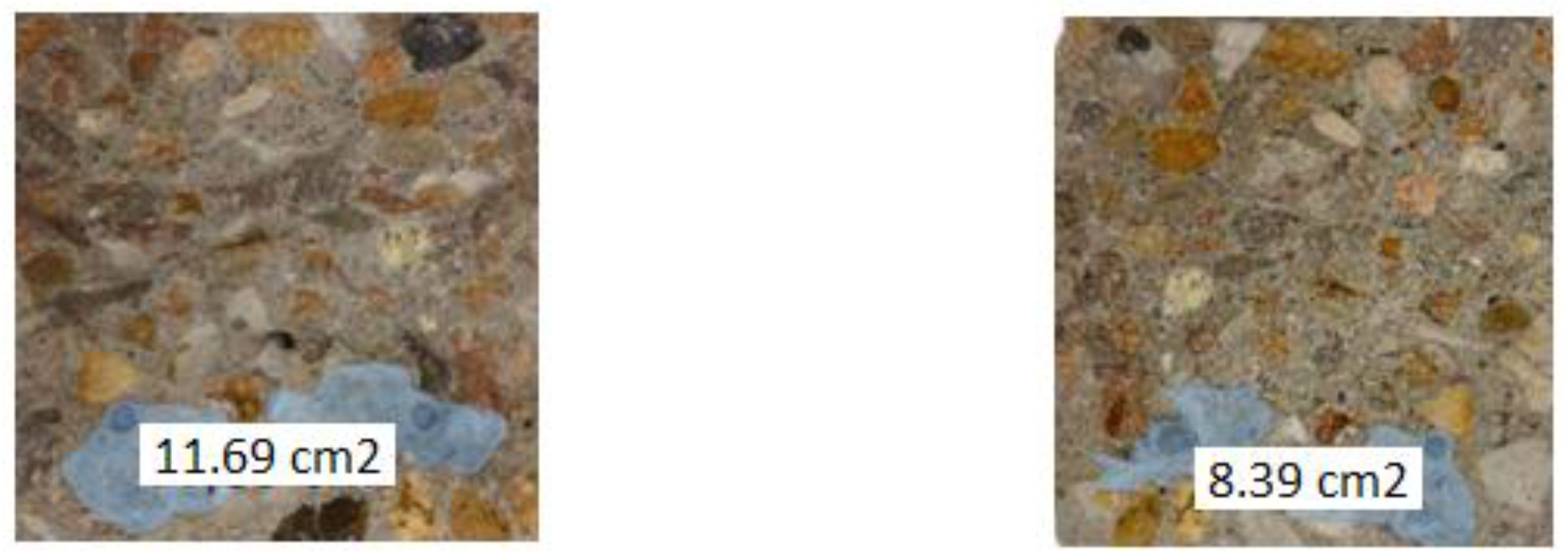
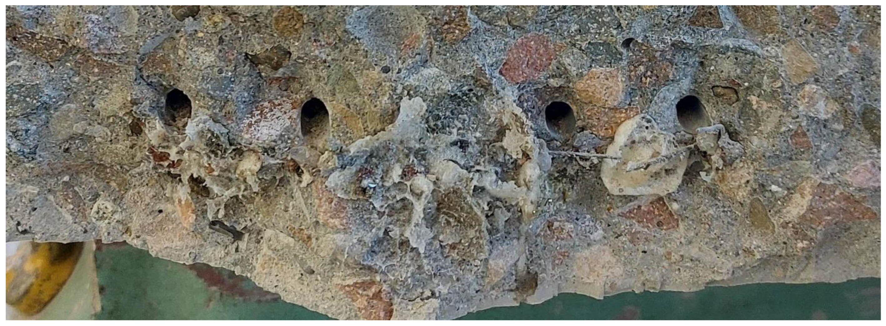
- In addition, the ability of PU to pour into a crack and fill it was checked. For this purpose, the beams were cracked in a 3-point bending test, and then macroscopic observations were made at the fractures.
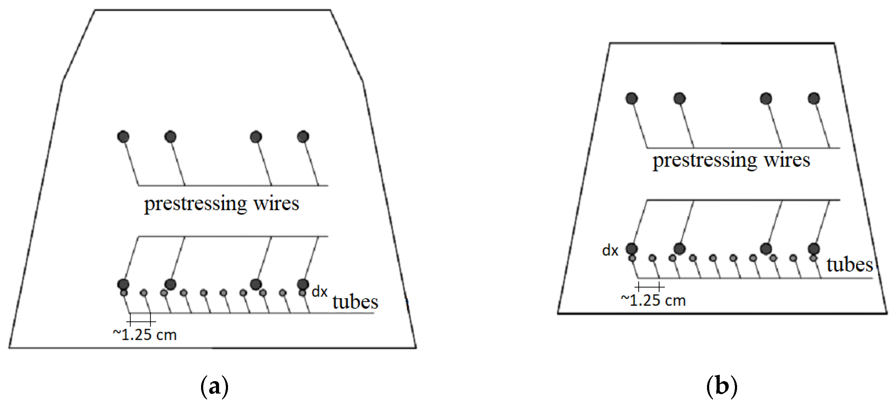
2.2.3. Test Methods for Railway Sleepers on an Industrial Scale
- Reference sleeper 1 (without tubes) and sleeper 2 with the addition of tubes—the crack resistance of the rail part was tested statically.
- Reference sleeper 3 (without tubes) and sleeper 4 with the addition of tubes—the crack resistance of the rail part was tested dynamically.
- Reference sleeper 5 (without tubes) and sleeper 6 with the addition of tubes—the crack resistance of the central part in the normal position was tested statically.
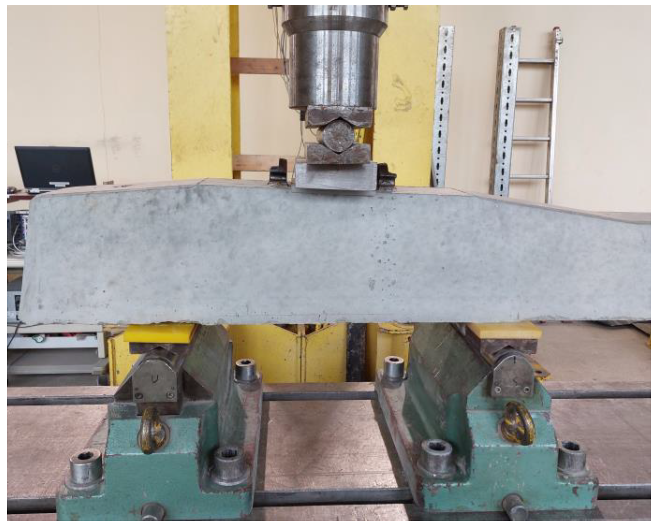
The Crack Resistance of the Rail Part Tested Statically
The Crack Resistance of the Rail Part Tested Dynamically
The Crack Resistance of the Central Part Tested Statically
3. Results
3.1. Results of Mortar Tests on a Laboratory Scale
3.1.1. Water Permeability Test
3.1.2. Water Absorption Test
3.1.3. Macroscopic Observations to Assess the Ability of the Healing Agent to Penetrate the Crack
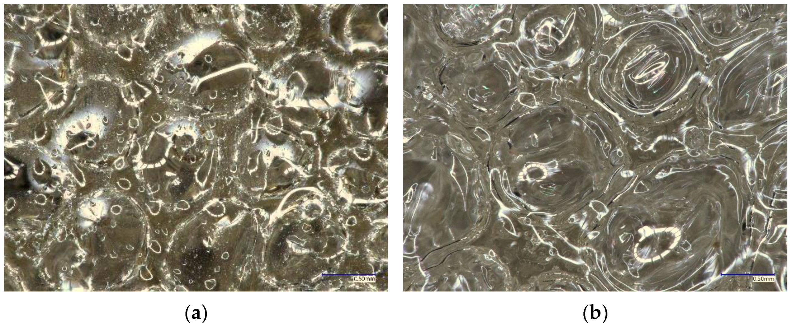
3.1.4. Microstructure Observations
3.2. Test Results Obtained on a Semi-Technical Scale
3.3. Results of Testing Railway Sleepers on an Industrial Scale
3.3.1. The Crack Resistance of the Rail Part Tested Statically
3.3.2. The Crack Resistance of the Rail Part Tested Dynamically
3.3.3. The Crack Resistance of the Central Part Tested Statically
4. Discussion
5. Conclusions
Author Contributions
Funding
Institutional Review Board Statement
Informed Consent Statement
Data Availability Statement
Conflicts of Interest
References
- PN-EN 13230-2:2016-06; Kolejnictwo—Tor—Podkłady i Podrozjazdnice Betonowe—Część 2: Podkłady Monoblokowe z Betonu Sprężonego. CEN—European Committee for Standardization: Brussels, Belgium, 2016.
- Frei, R.; Mc William, R.; Derrick, B.; Purvis, A.; Tiwari, A.; Serugendo, G. Self-healing and self-repairing technologies. Int. J. Adv. Manuf. Technol. 2013, 69, 1033–1061. [Google Scholar] [CrossRef]
- Rooij, M.; Tittelboom, K.; Belie, N.; Schlangen, E. State-of-the-Art Reports. In Self-Healing Phenomena in Cement-Based Materials; Editors Technical Committee 221-SHC: Self-Healing Phenomena in Cement-Based Materials; Springer: Berlin/Heidelberg, Germany, 2013. [Google Scholar]
- Danish, A.; Mosaberpanah, M.A.; Salim, M.U. Past and present techniques of self-healing in cementitious materials: A critical review on efficiency of implemented treatments. J. Mater. Res. Technol. 2020, 9, 6883–6899. [Google Scholar] [CrossRef]
- Indhumathia, S.; Dinesh, A.; Pichumani, M. Diverse perspectives on self healing ability of Engineered Cement Composite—All-inclusive insight. Constr. Build. Mater. 2022, 323, 126473. [Google Scholar]
- Zhang, W.; Zheng, Q.; Ashour, A.; Han, B. Self-healing cement concrete composites for resilient infrastructures: A review. Compos. Part B Eng. 2020, 189, 107892. [Google Scholar] [CrossRef]
- Ferrara, L.; Krelani, V.; Carsana, M. A “fracture testing” based approach to assess crack healing of concrete with and without crystalline admixtures. Constr. Build. Mater. 2014, 68, 535–551. [Google Scholar] [CrossRef]
- Xue, C. Cracking and autogenous self-healing on the performance of fiber-reinforced MgO-cement composites in seawater and NaCl solutions. Constr. Build. Mater. 2022, 326, 126870. [Google Scholar] [CrossRef]
- Zhang, J. Recent advance of MgO expansive agent in cement and concrete. J. Build. Eng. 2022, 45, 103633. [Google Scholar] [CrossRef]
- Termkhajornkit, P.; Nawab, T.; Yamashiro, Y.; Saito, T. Self-healing ability of fly ash–cement systems. Cem. Concr. Compos. 2009, 31, 195–203. [Google Scholar] [CrossRef]
- Sahmaran, M.; Keskin, S.B.; Ozerkan, G.; Yaman, I.O. Self-healing of mechanically-loaded self-consolidating concretes with high volumes of fly ash. Cem. Concr. Compos. 2008, 30, 872–879. [Google Scholar] [CrossRef]
- Schwantes-Cezario, N.; Cremasco, L.V.; Medeiros, L.P.; Teixeira, G.M.; Albino, U.B.; Lescano, L.E.A.M.; Matsumoto, L.S.; de Oliviera, A.G.; da Silva, P.R.C.; Toralles, B.M. Potential of cave isolated bacteria in self-healing of cement-based materials. J. Build. Eng. 2022, 45, 103551. [Google Scholar] [CrossRef]
- Wiktor, V.; Jonkers, H.M. Bio-chemical self-healing agent to prevent reiforcement corrosion in concrete. In Proceedings of the 2nd International Conference on Self-healing Materials, Chicago, IL, USA, 28 June–1 July 2009; p. 118. [Google Scholar]
- Nodehi, M.; Ozbakkaloglu, T.; Gholampour, A. A systematic review of bacteria-based self-healing concrete: Biomineralization, mechanical, and durability properties. J. Build. Eng. 2022, 49, 104038. [Google Scholar] [CrossRef]
- Jonkers, H.M. Bacteria-based self-healing concrete. Heron 2011, 56, 55–57. [Google Scholar] [CrossRef]
- Shashank, B.S.; Praveen Kumar, K.; Nagaraja, P.S. Fracture behavior study of self-healing bacterial concrete. Mater. Today Proc. 2022, 60, 267–274. [Google Scholar] [CrossRef]
- Al-Ansari, M.; Abu-Taqa, A.G.; Hassan, M.M.; Senouci, A.; Milla, J. Performance of modified self-healing concrete with calcium nitrate microencapsulation. Constr. Build. Mater. 2017, 149, 525–534. [Google Scholar] [CrossRef]
- Al-Tabba, A.; Giannaros, P.; Kanellopoulos, A. The effect of varying volume fraction of microcapsules on fresh, mechanical and self-healing properties of mortars. Constr. Build. Mater. 2016, 122, 577–593. [Google Scholar]
- Dai, Z.; Tsangouri, E.; Van Tittelboom, K.; Zhu, X.; Gilabert, F.A. Understanding fracture mechanisms via validated virtual tests of encapsulation-based self-healing concrete beams. Mater. Des. 2022, 213, 110299. [Google Scholar] [CrossRef]
- de Oliveira, T.A.; Bragança, M.; D’Orey, G.P.; Pinkoski, I.M.; Carrera, G. The effect of silica nanocapsules on self-healing concrete. Constr. Build. Mater. 2021, 300, 124010. [Google Scholar] [CrossRef]
- Li, W.; Wei, Q.; Chen, Q.; Jiang, Z. Microencapsulation and evaluation of styrene maleic anhydride/epoxy for mechanical triggering self-healing of cementitious materials. Cem. Concr. Compos. 2021, 124, 104247. [Google Scholar] [CrossRef]
- Wang, X.; Xing, F.; Zhang, M.; Han, N.; Qian, Z. Experimental Study on Cementitious Composites Embedded with Organic Microcapsules. Materials 2013, 6, 4064–4081. [Google Scholar] [CrossRef] [PubMed]
- Dry, C. Matrix cracking repair and filling using active and passive modes for smart timed release of chemicals from fibers into cement matrices. Smart Mater. Struct. 1994, 3, 118–123. [Google Scholar] [CrossRef]
- Dry, C. Smart earthquake resistant materials (using time released adhesives for damping, stiffening, and deflection control). In Proceedings of the 3rd ICIM/ECSSM, Lyon, France, 3–5 June 1996; pp. 958–967. [Google Scholar]
- Dry, C. Smart multiphase composite materials that repair themselves byarelease of liquids that become solids. In Symposium on Smart Structures and Materials; SPIE: Orlando, FL, USA, 1994; pp. 62–70. [Google Scholar]
- Van Tittelboom, K.; De Belie, N. Self-healing concrete: Suitability of different healing agents. Int. J. 3r’s 2010, 1, 12–21. [Google Scholar]
- Van Tittelboom, K.; De Belie, N. Self-healing concrete by the internal release of adhesive from hollow glass tubes embedded in the matrix. In Proceedings of the 2nd International Conference on Self-healing Materials, Chicago, IL, USA, 29 June 2009; p. 101. [Google Scholar]
- Van Mullem, T.; Anglani, G.; Dudek, M.; Vanoutrive, H.; Bumanis, G.; Litina, C.; Kwiecień, A.; Al-Tabbaa, A.; Bajare, D.; Stryszewska, T.; et al. Addressing the need for standardization of test methods for self-healing concrete: An interlaboratory study on concrete with macrocapsules. Sci. Technol. Adv. Mater. 2020, 21, 661–682. [Google Scholar] [CrossRef] [PubMed]
- Id—101 Warunki Techniczne i Odbioru Podkładów i Podrozjazdnic Strunobetonowych WTWiO—ILK3a—5187/01/05; PKP Polskie Linie Kolejowe S.A.: Warszawa, Poland, 2010.


| Sample Identification | PU0 | PU1 | PU2 | PU3 | PU4 | PU5 |
|---|---|---|---|---|---|---|
| Water content % | 0 | 1 | 2 | 3 | 4 | 5 |
| Picture |  | 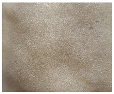 | 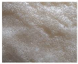 | 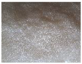 |  | 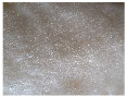 |
| Fr0 (kN) | Frr (kN) | Fr0.05 (kN) | Fr0.5 (kN) | FrB (kN) | |
|---|---|---|---|---|---|
| Guidelines WTWiO/ requirements Id—101 | 161.20 | >200.00 | >300.00 | --- | >450.00 |
| Test results of the reference railway sleeper | 211.20 | 351.20 | 391.20 | 688.71 | |
| Test results of the railway sleepers with tubes filled with PU | 211.20 | 331.20 | 381.20 | 690.86 |
| Fr0 (kN) | Frr (kN) | Fr0.05 (kN) | Fr0.5 (kN) | FrB (kN) | |
|---|---|---|---|---|---|
| Guidelines WTWiO/ requirements Id—101 | 161.20 | >243.00 | >356.40 | ||
| Test results of the reference railway sleeper | 201.20 | 321.20 | 421.10 | 481.20 | |
| Test results of the railway sleepers with tubes filled with PU | 201.20 | 291.20 | 431.20 | 491.20 | |
| Fc0 (kN) | Fcr (kN) | Fc0.5 (kN) | FcB (kN) | |
|---|---|---|---|---|
| Guidelines WTWiO/ requirements Id—101 | 27.61 | >30.00 | --- | >65.00 |
| Test results of the reference railway sleeper | 37.61 | 62.61 | 85.61 | |
| Test results of the railway sleepers with tubes filled with PU | 32.61 | 52.61 | 83.86 |
Disclaimer/Publisher’s Note: The statements, opinions and data contained in all publications are solely those of the individual author(s) and contributor(s) and not of MDPI and/or the editor(s). MDPI and/or the editor(s) disclaim responsibility for any injury to people or property resulting from any ideas, methods, instructions or products referred to in the content. |
© 2024 by the authors. Licensee MDPI, Basel, Switzerland. This article is an open access article distributed under the terms and conditions of the Creative Commons Attribution (CC BY) license (https://creativecommons.org/licenses/by/4.0/).
Share and Cite
Dudek, M.; Stryszewska, T. Self-Healing of Cracks in Cementitious Materials as a Method of Improving the Durability of Pre-Stressed Concrete Railway Sleepers. Materials 2024, 17, 760. https://doi.org/10.3390/ma17030760
Dudek M, Stryszewska T. Self-Healing of Cracks in Cementitious Materials as a Method of Improving the Durability of Pre-Stressed Concrete Railway Sleepers. Materials. 2024; 17(3):760. https://doi.org/10.3390/ma17030760
Chicago/Turabian StyleDudek, Marta, and Teresa Stryszewska. 2024. "Self-Healing of Cracks in Cementitious Materials as a Method of Improving the Durability of Pre-Stressed Concrete Railway Sleepers" Materials 17, no. 3: 760. https://doi.org/10.3390/ma17030760