Review

Advancements and Challenges in High-Capacity Ni-Rich Cathode Materials for Lithium-Ion Batteries

by
Mehdi Ahangari
,
Benedek Szalai
,
Josue Lujan
,
Meng Zhou
* and
Hongmei Luo
*
Department of Chemical and Materials Engineering, New Mexico State University, Las Cruces, NM 88003, USA
*
Authors to whom correspondence should be addressed.
Materials 2024, 17(4), 801; https://doi.org/10.3390/ma17040801
Submission received: 11 January 2024 / Revised: 5 February 2024 / Accepted: 5 February 2024 / Published: 7 February 2024

Abstract

:
Nowadays, lithium-ion batteries are undoubtedly known as the most promising rechargeable batteries. However, these batteries face some big challenges, like not having enough energy and not lasting long enough, that should be addressed. Ternary Ni-rich Li[NixCoyMnz]O2 and Li[NixCoyAlz]O2 cathode materials stand as the ideal candidate for a cathode active material to achieve high capacity and energy density, low manufacturing cost, and high operating voltage. However, capacity gain from Ni enrichment is nullified by the concurrent fast capacity fading because of issues such as gas evolution, microcracks propagation and pulverization, phase transition, electrolyte decomposition, cation mixing, and dissolution of transition metals at high operating voltage, which hinders their commercialization. In order to tackle these problems, researchers conducted many strategies, including elemental doping, surface coating, and particle engineering. This review paper mainly talks about origins of problems and their mechanisms leading to electrochemical performance deterioration for Ni-rich cathode materials and modification approaches to address the problems.

1. Introduction

In recent decades, the urgent global issues of ever-increasing fossil fuel demand and the alarming threat of global warming have spurred the development of renewable and green energy sources [1]. Within this array of sustainable energy options—for example, hydroelectric, solar, tide, or wind, which all contribute to the global energy needs—rechargeable lithium-ion batteries (LIBs) have prominently emerged as the most sought-after for numerous practical applications, decisively spearheading the electrification of vehicles. This preference arises from their distinctive blend of characteristics, including their lightweight design, impressive power output, substantial energy capacity (ranging from 250 to 693 Wh L−1 and 100 to 265 Wh kg−1), relatively long service life, desirable rate capability, safety features, and minimal environmental impact. Currently, LIBs have achieved widespread success in small-scale portable consumer electronic devices such as cellular phones and laptop computers [2,3]. However, when it comes to utilization of the current state-of-the-art LIBs in more substantial applications, such as passenger electric vehicles (EVs), hybrid electric vehicles, and large-scale energy storage systems, there are formidable challenges and requirements (as detailed in Table 1) that must be meticulously addressed to compete with traditional internal combustion engine vehicles and receive wider consumer acceptance. These challenges encompass the imperative to meet demanding criteria, such as fast charging and rating capabilities, elevated energy, power density for starting, accelerating, and uphill driving, cost-effectiveness, battery safety under harsh conditions at elevated temperatures, and prolonged lifespan [4]. One way to reduce costs is to utilize high gravimetric and volumetric energy density materials, thereby requiring a smaller number of needed materials. In addition to driving range, charging time is also central to customer experience [5,6,7,8,9,10].
The electrochemical characteristics of LIBs are primarily governed by the properties of their cathode materials. While every component of the battery system plays a vital role in achieving optimal performance and continues to be the focus of extensive research, a notable technical bottleneck in LIBs technology pertains to the limited capacity of cathode materials, typically falling below 270 mAh g−1. This inferior capacity stands in contrast to the more robust capacity of graphite, SnO2, Sn, and Si anode materials, which can reach up to 350, 782, 994, and 4200 mAh g−1, respectively [12]. In order to resolve the capacity shortfall exhibited by cathode materials, immense efforts have been directed on research and development endeavors aimed at creating new materials and refining existing materials that combine high-capacity and high-voltage. Cathode materials are typically categorized into the three most prominent classes: (1) Layered oxide LiMO2 (M = Mn, Co, and Ni) structure, (2) Spinel-framework LiM2O4 (M = Mn, Co, and Ni) structure, and (3) Olivine LiMPO4 (M = Fe, Mn, Co, and Ni) structure [13]. These categories exhibit varying actual capacities, typically falling within the range of 120 mAh g−1 to 210 mAh g−1 [14,15,16]. Among the various materials presently available explored as potential candidates for battery cathodes, layered transition metal oxides (LTMOs) have emerged as particularly promising options. Layered oxide materials (for example LiCoO2 and LiNixCoyMnzO2) with a layered lattice α-NaFeO2 hexagonal structure and R-3m space group play a crucial role in facilitating the reversible (de)intercalation of lithium ions. In this structure, lithium ions and TM cations are placed within octahedral 3a and 3b sites, respectively, while oxygen anions occupy the octahedral 6c sites, showing a cubic close-packed arrangement (as depicted in Figure 1) [17].
The evolution of Ni-rich cathode materials traces its roots to the constrained development of LiCoO2 electrodes. Despite the excellent performance of LiCoO2, limitations such as practical delivery of only 50% of the theoretical capacity (140 mAh g−1), high cost, and the material’s toxic property, hinder its application in EVs. As a response, rigorous research endeavors have been undertaken to replace Co with alternative elements such as Ni and Mn in cathode hosts. However, the absence of Co in the layered oxide structure often results in structural instability at low-temperature operations and lower electronic conductivity [19,20]. N. Zhang et al. [21] reported that Co helps Ni and Li ordering, and in Co absence, more Ni and Li ion-exchange sites are possible. Also, Mn provides structural stability, as its oxidation state is +4 throughout electrochemical cycling [22]. Consequently, by taking partial advantage of the high capacity of LiNiO2, the layered character of LiCoO2, and the low cost and thermal stability of LiMnO2, LiNixCoyMnzO2 (NCM) cathode materials have appeared as viable contenders to substitute the traditional LiCoO2 cathode, addressing some of the inherent challenges associated with Co-based formulations [23,24,25]. Ni-rich layered oxide cathode materials (x > 0.5) have attracted great interest as the leading candidates in this domain. This enthusiasm is primarily fueled by their exceptional attributes, including a superior actual capacity exceeding 170 mAh g−1, a volume change by less than 2% during Li insertion/extraction, and a higher average operating cutoff potential surpassing 3.4 V [26,27,28,29]. While Ni-rich cathode materials have received great attention for their remarkable attributes, such as high capacity and energy density (exceeding 600 Wh kg−1), they are susceptible to a range of significant drawbacks. These issues include premature capacity degradation, severe structural and thermal instability, limited calendar life, electrolyte decomposition, intrinsic low-rate capability, rapid voltage decay leading to sluggish Li+ ion transport dynamics, and safety concerns. These intrinsic defects have posed significant obstacles to their widespread commercialization, particularly in the context of EVs [30,31,32,33,34]. In this review, we delve into the main mechanisms contributing to the failure of Ni-rich cathode materials in LIBs. By exploring these mechanisms in depth, we shed light on key strategies aimed at enhancing both the electrochemical and thermal properties of these materials.

2. Origin of Problems

The broad applications of Ni-rich cathode materials in the industry have faced significant challenges, primarily stemming from two issues: performance degradation and safety concerns. C. Yoon et al. [35] conducted a study highlighting that an escalation in Ni concentration within NCM cathode materials resulted in a notable decline in capacity retention. According to their research, the increase in Ni content in NCM cathode materials correlated with an elevated discharge capacity, ranging from 160 mAh g−1 in NCM111 to surpassing 240 mAh g−1 in LiNiO2. However, it is essential to highlight that capacity retention experienced a decrease, diminishing from 97% for NCM111 to 70% for LiNiO2. Another investigation by G. Nam et al. [36] indicated an augmentation in Ni content in layered oxides, accompanied by sacrifices in electrochemical performance and thermal stabilities due to the weaker Ni−O bonds destabilizing the crystal structure and increasing the anisotropic volume change upon Li-extraction/insertion, leading to a significant increase in microcrack propagation (refer to Figure 2). In Ni-rich active materials, key challenges fall into two categories: crystal structure-driven degradation, and instability of the electrode material interface near the surface. One major issue contributing to structural degradation is Li/Ni cation mixing which appears particularly in NCM materials with a Ni content more than 80%. This mixing leads to various deteriorations in the cathode material, such as pulverization, phase transition, and microcrack propagation, which makes it difficult to reach high capacity retention in cycling and rating performance. Regarding electrode-electrolyte reaction, electrolyte decomposition and gas evolution are significant consequences, posing thermal instability and safety hazards, especially in EVs. These problems will be thoroughly discussed in this section, providing valuable insight for researchers studying cathode materials for LIBs.

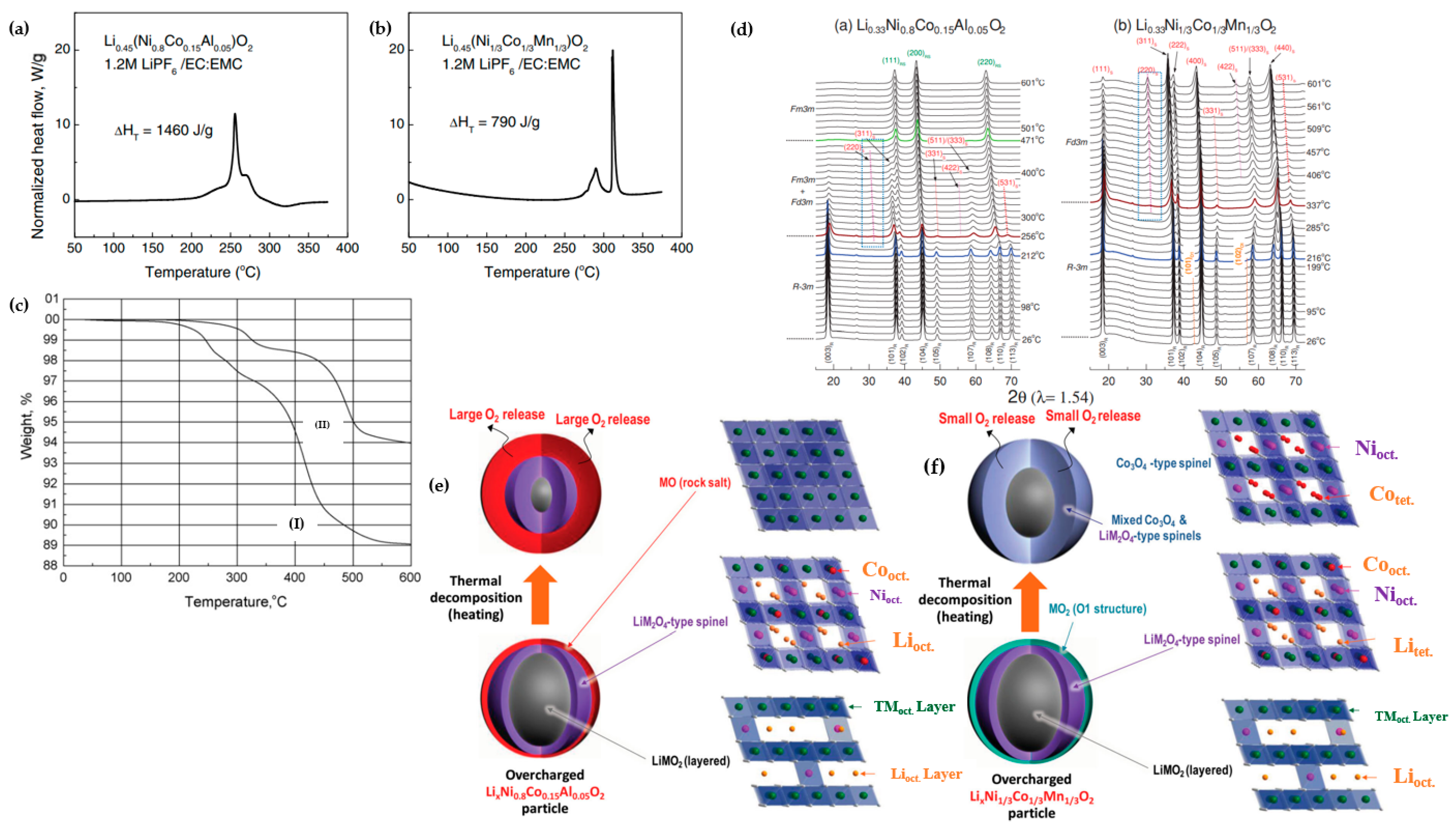
2.1. Understanding the Structural Instability

The cathodes of LIBs function through the reversible insertion and extraction of Li ions. This process is expected to transpire without inducing any significant permanent alterations to the crystal structure, as these cathodes need to withstand hundreds to thousands of charging and discharging cycles. In Ni-enriched cathode materials, the coexistence of mixed-valent Ni2+ and Ni3+ leads to partial Li/Ni structural disordering. Li/Ni cation mixing degrades the capacity of Ni-rich cathode materials and hinders the mobility of both Li and Ni ions (Figure 3a). The exchange between Ni and Li occurs during the synthesis process and cycling in LTMO structures. In these structures, Ni2+ preferentially occupies the interlayer Li 3b site over Ni3+, as Ni2+ and Li+ have similar sizes (0.69 Å and 0.76 Å, respectively) and a lower energy barrier for Ni2+ ions’ migration from their native 3b to Li+ 3a sites. From an ionic model perspective, the layer structure of LiNiO2 is expressed as [Ni3+]3a−[O2−]6c−[Li+]3b−[O2−]6c. Ni substitution in the Li 3b layer accompanies a change in Ni valence to maintain the electroneutrality principle, and is represented as [Ni2+]3a−[O2−]6c−[Ni2+]3b−[O2−]6c [37]. This promotes Li+/Ni2+ exchange, with a higher probability compared to the lower likelihood of such exchange for Co3+ and Mn4+.
The explanation for the structural instability induced by the exchange of Li and Ni can be elucidated as follows. As shown in Figure 3b, Li ions diffuse within the layered oxide structure through two pathways: The first involves Li ions moving from one octahedral site to the next octahedral site by hopping directly through the oxygen dumbbell directly, termed oxygen dumbbell hopping (ODH), with an activation barrier ranging from 0.75 to 0.91 eV. The second pathway entails Li ions diffusing from one octahedral site to the next octahedral site by hopping through a divacancy left by Li diffusion to an intermediate tetrahedral site surrounded by TMs, known as tetrahedral site hopping (TSH). The corresponding energy barrier for TSH ranges from 0.36 to 0.54 eV. These values are influenced not only by the electrostatic interaction between Li ions in the activated state and the TM cations but also by the strain effect, which encompasses the size of the saddle point for the oxygen dumbbell in ODH and the size of the tetrahedral site for TSH [38,39].
Figure 3. (a) The α-NaFeO2 type structure of layered NCM materials, featuring one pair of Li/Ni exchange. Reprinted from Ref. [38] with permission from American Chemical Society, and (b) A schematic representation is provided, elucidating the Li ion diffusion pathways through ODH and TSH. Green, red, and grey dots stand for TM ions, oxygen, and Li ions, respectively [40].
Materials 17 00801 g003
The presence of anti-site Ni2+ hampers Li ion diffusion in the Li-layer through three mechanisms: Firstly, as Li ion migration in LTMO2 occurs via 2D diffusion within the Li layer, the presence of anti-site Ni2+ disrupts the Li ion diffusion path. Secondly, the higher charge of anti-site Ni2+ should result in stronger electrostatic repulsion of migrating Li ions, consequently leading to lower Li ion mobility. Thirdly, the activation energy of both ODH and TSH diffusion is closely associated with the strain effect, determined by the c-lattice parameter (Li slab space). Due to the stronger interaction of O−Ni2+−O compared to that of O−Li+−O, the presence of anti-site Ni2+ reduces the Li slab space, leading to a higher activation barrier for lithium diffusion [38]. The microscopic mechanisms can be explained in the following ways: (1) When Ni ions with valence states of 2+, 3+, and 4+ are replaced with an Li ion, the local coulombic interaction of the corresponding TM ions changes, and the network of super-exchange interactions among the TM ions is also disrupted due to the absence of localized d-orbital electrons in the anti-site Li ions. Thus, both the coulombic interaction and super-exchange interaction contribute to the distortion force, resulting in anisotropic stress within the bulk structure [38,41,42,43]. (2) During electrochemical cycling, the anti-site Ni ions would gradually migrate to the particle surface due to the low energy barrier for Ni2+ migration (∼0.25 eV). This migration process results in Ni depletion in the bulk, leading to structural instability, and consequently, cathode voltage and capacity fade [44].
Lin et al. [45] provided evidence of the occurrence of lattice distortion in NCM811 during cycling, a phenomenon that led to the propagation of microcracks and subsequent capacity decay. The researchers underscored that the generation of intragranular cracks originating from the bulk of primary particles was accountable for the degradation in electrochemical performance observed in NCM811 (Figure 4a). In their findings, they detailed the development of a premature intragranular crack within the NCM811 primary particle. As shown in Figure 4b, this crack exhibited a length of 50 nm along the (003) plane, identified as the preferential direction for Li/Ni anti-site formation. Notably, the primary particle underwent a phase transformation from a layered structure to a rock-salt structure, extending to 440 nm (Figure 4c,d), indicative of the growth of the transformed structure region. The structural evolution was elucidated by the reduction of Ni ions to a lower state and the involvement of oxygen in redox reactions. This resulted in the formation of additional oxygen vacancies and a lowered migration barrier for TM cations in the Li layer, leading to the aggravation of rock-salt domain [46,47]. Consequently, Li+ sites were occupied by Ni2+. With an increase in the cycling number, an augmented occurrence of Li/Ni anti-site defects at the crack edge and the aggregation of Ni ions in the Li ions diffusion channel was observed, confirmed by EDS mapping shown in Figure 4e. This led to an elevation in the columbic repulsion of cations due to the higher charge state of Ni2+ compared to Li+, coupled with increased lattice distortion by tensile strain due to the expansion of d-spacing of the (003) plane. As the cycling continued, the tensile stress in the deformation region surpassed the tensile limit of the transformed structure, resulting in the fracture of the distorted lattice (Figure 4f). Notably, the fragility of the rock-salt phase compared to the layered phase played a crucial role in the fracture mechanism, leading to lattice rupture along the (003) plane.
Li/Ni lattice disordering induces partial interference disruption in the (003) plane, resulting in a reduction of the intensity of the (003) peak. Concurrently, the constructive interference of peaks in the (104) plane increases, leading to a decrease in the I(003)/I(104) ratio. Based on XRD analysis, the increase in Ni content did not change the crystal structure of materials (hexagonal α-NaFeO2), except for the I(003)/I(104) ratio, which decreased in higher Ni concentration materials. It is worth mentioning that the I(003)/I(104) ratio is indirectly a sign of Li/Ni cation mixing in the lithium layer and a ratio of more than 1.2 signifies a well-ordered structure. Table 2 provides I(003)/I(104) ratio measurements for a range of NCM cathode materials.
Destabilization of mechanical integrity in cathodes is attributed to the large and nonuniform lattice contraction, intensified by the abrupt H2 → H3 phase transition. This phenomenon leads to the formation of numerous microcracks, particularly noticeable with an increased Ni fraction. In Ni-enriched cathode materials, structural degradation is characterized by a transition from the layered phase (R-3m) to a spinel-like phase (Fd-3m) and a rock-salt phase (Fm-3m) [49,50]. In these cathode materials with x ≥ 0.8, a sequence of phase transitions, including the transition from the layered structure (H1) to a monoclinic phase (M) and two hexagonal phases (H2 and H3), takes place. The phase transition from H2 to H3, occurring above 4.15 V, has been identified as a significant contributor to rapid capacity fading in NCM and NCA materials, resulting in an abrupt shrinkage of approximately 0.3 Å in the c-direction. During discharge, the transition from H3 to H2 causes an equal expansion in the lattice. As this abrupt anisotropic volume change repeats during cycling, the structural stability of the cathode is gradually compromised, ultimately leading to capacity fading [51,52]. Differential capacity vs. voltage profiles (dQ dV−1) for NCM materials with different Ni molar ratios confirm that phase transitions occur at higher Ni fractions, where the NCM811 curve deviates significantly from the corresponding ones for NCM111 and NCM622 (Figure 5). Up to 3.8 V, there is a peak at around 3.7 V during charging for all samples. For higher potential, the curve for NCM811 exhibits sharp peaks due to phase transition from M → H2 at around 3.85 V, and H2 → H3 at around 4.15 V. As cycling progresses, NCM111 demonstrates the most stable structure compared to Ni-rich samples. The absence of phase transition H2 → H3 in lower Ni concentration materials reflects the good reversibility and stability of the host structure [48]. During this phase transition, TMs migrate to vacant Li sites, accompanied by changes in lattice constants and volume with each charge–discharge cycle, leading to the accumulation of local stress concentrations within particle boundaries, ultimately resulting in crack formation. The cracks propagate through the cathode particle, allowing electrolyte solution infiltration. Upon contact with the exposed surfaces of the cracked cathode, the electrolyte solution triggers further deterioration of the structural and electrochemical properties. This deterioration is exacerbated by the reaction with highly unstable reactive Ni4+ (resulting from the reduction of Ni4+ to Ni2+, accompanies by O2 release) and the continuous accumulation of a NiO-like impurity layer [53].
Kim et al. [53] investigated the influence of Ni enrichment on the volume, lattice parameters, and microstructure of NixCo(1−x)/2Mn(1−x)/2 (x = 1, 0.98, 0.96, 0.94, 0.92, and 0.90). As shown in Figure 6a, the a-axis lattice parameter consistently decreased with the NCM composition, up to 2%. In contrast, the c-axis parameter initially expanded and then abruptly contracted beyond 4.2 V due to the H2 → H3 phase transition. The contraction of the a-lattice parameter was limited to about 2%, while the reduction for the c-axis parameter was more significant, resulting in highly anisotropic volume contraction. Figure 6a illustrates a pronounced contraction in the c-axis parameter for LiNiO2 compared to NCM90 (−7.9% and −5.7%, respectively). The unit cell volume displayed a similar trend, diminishing beyond 4.2 V, with increased volume changes as the Ni fraction rose, measuring −7.8% for NCM90 and −10% for LNO (Figure 6b). In Figure 6c, the ∆c and ∆V curves indicated that the primary cause of volume contraction in cathodes with higher Ni fractions was the reduction along the c-direction during the H2 → H3 phase transition. This reduction induced local stress concentrations at the boundaries of primary particles, serving as sites for crack nucleation. Cross-sectional SEM images of two samples, NCM92 and NCM96, distinctly revealed mechanical damage induced by the H2 → H3 phase transition during cell cycling. Microcracks propagated to the surface of NCM96, whereas in the case of NCM92 cathodes, microcrack propagation was arrested before reaching the particle surface due to lower volume changes (Figure 6d). The scanning spreading resistance microscopy (SSRM) technique was employed to determine that the electronically dead region (near-zero electronic conductivity) of NCM96 was fully charged to 4.3 V after the first and 100 cycles. Dark regions were observed, indicating electronically inactive areas due to electrolyte penetration and surface degradation, accentuated by microcrack propagation (Figure 6e).
The mechanism of the phase transition in Ni-enriched materials can be explained by the level of removal of Li from insertion oxides or SOC through various mechanisms. Initially, lithium removal occurs randomly, but as vacancies accumulate, the remaining Li ions may undergo an ordering transition. In most oxides, Li ionizes to Li+ during removal, creating electronic holes in the host material. This introduction of electronic holes can trigger phase transitions through various pathways. If, at a specific Li composition, the material exhibits insulating or semi-conducting behavior, Li removal can induce a transition to a metallic state once a sufficient number of mobile holes (electrons) are generated in the host. The shift in valence of ions within the host material may alter the short-range interaction between them, either through size changes or shifts from ionic to more covalent bonding. This evolution in short-range interaction, coupled with the change in electrostatic energy resulting from shifts in valence and the removal of ions, can lead to structural modifications in the host [55]. For example, in the case of NCM811, substantial delithiation (charging) resulted in the lattice parameters a and b of LixNCM811 shrinking for 1.00 > x > 0.25, followed by a slight expansion for 0.25 > x. Meanwhile, the c-lattice parameter initially increased for 1.00 > x > 0.50 and then decreased for 0.25 > x [56]. The microcrack propagation due to volume changes in cathode materials, which is more pronounced particularly in terms of density and width in Ni-rich cathode materials, could serve as channels for electrolyte penetration, exposing the particle interior to deleterious electrolyte reactions.
G. W. Nam et al. [36] investigated the effect of level of SOC in structural degradation for Li[Ni1−x−yCoxAly]O2 cathodes with compositions (1 − x − y = 0.8, 0.88, and 0.95). Based on their research, NCA80 retained a substantial fraction of the H2 phase even though it was charged to 4.3 V, while the NCA88 and NCA95 H2 → H3 phase transition was completed at lower potential and at higher acceleration rate, which did not allow the mechanical strain to dissipate and led to localized strain concentration, from which microcracks nucleated along the grain boundaries. The areal fraction was 5% for NCA80, 14.0% for NCA88, and 25.7% for NCA95 after charging to 4.3 V, and the length and density of cracks were visibly increased. It was concluded from these measurements that NCA95 fully charged to 4.3 V experienced pulverization into clumps of constituent primary particle due to a high anisotropic volume change, and it was one of the main culprits for its cycling deterioration. Figure 7a,b explain the reason behind different capacity deterioration behaviors in NCA compositions. When NCA electrodes were charged and discharged, the microcracks were not completely closed, showing irreversible microstructure evolution, especially for NCA95. The severity of microcracking in the NCA88 and NCA95 was significant enough to permit electrolyte penetration, rendering the particle susceptible to electrolyte attack and resulting in an accelerated rate of capacity fading due to the reaction with Ni4+ species and the formation of NiO-like rock-salt phase on the cathode surface [57]. Park et al. [58] conducted a comprehensive investigation aimed at elucidating the factors contributing to capacity fading in NCA95, NCA88, and NCA80 materials. These materials underwent cycling under various conditions, including the upper range (3.76–4.3 V) and lower depths of discharge (DOD) at 60% (2.7–4.0 V) and 100% DOD (2.7–4.3 V). The results, illustrated in Figure 7c, revealed a more pronounced capacity retention decline at the upper DOD (65.6%) compared to other conditions. Analysis of the dQ dV−1 curves for NCA95 (Figure 7d–f) highlighted the significant influence of DOD levels on capacity retention. Specifically, the redox peaks corresponding to the H2 → H3 phase transition exhibited a faster decay in height during cycling at the upper 60% DOD than at 100% DOD. Conversely, the redox peaks associated with the H1 → M phase transition at the lower 60% DOD remained relatively stable, indicating the host structure’s robustness in this DOD range. Figure 7g depicted the volume change of NCA95 during cycling, revealing the highest value for cycling at 100% DOD, conventionally associated with microcrack propagation in particles. Conversely, the areal fraction of microcracks at the upper DOD was twice that at 100% DOD, as can be seen in Figure 7h–j. These findings emphasized the critical influence of DOD width and limit on microcrack resistance. Extending the investigation to NCA88 and NCA80 samples, cross-sectional SEM images (Figure 7k–n) after 100 cycles at the upper DOD confirmed that materials with a higher 80% Ni fraction experienced notable impacts on cycling performance due to DOD limit and width. The authors concluded that the primary cause of severe microcrack propagation at the upper DOD was attributed to the insufficient relief of stress generated by the H2 → H3 phase transition at 3.76 V, necessitating additional lithiation. The thickness of the NiO-like rock-salt phase is highly dependent on the composition of cathode materials. According to transmission electron microscopy (TEM) images (Figure 8a,b) provided by Park et al. [59], surface damage for Ni0.9Co0.05Mn0.05 (NCM90) fully discharged after 1000 cycles appeared as residual microcracks through which the electrolyte can infiltrate, and were discernible in the cathode particle, in contrast to hairline cracks in NCM811. Simultaneously, the thickness of the damaged layer formed on the exterior surfaces and near microcracks attributed to the rock-salt impurity and reactivity of the cathode with the electrolyte was higher for the NCM90 than NCM811 particle, at 20 and 3 nm, respectively (Figure 8c,d). The increased thickness of the rock-salt impurity, stemming from microcrack propagation and electrolyte infiltration, has the potential to elevate the charge transfer resistance associated with Li ion diffusion. This phenomenon can contribute to increased polarization and kinetic losses in capacity, particularly at high C-rates.

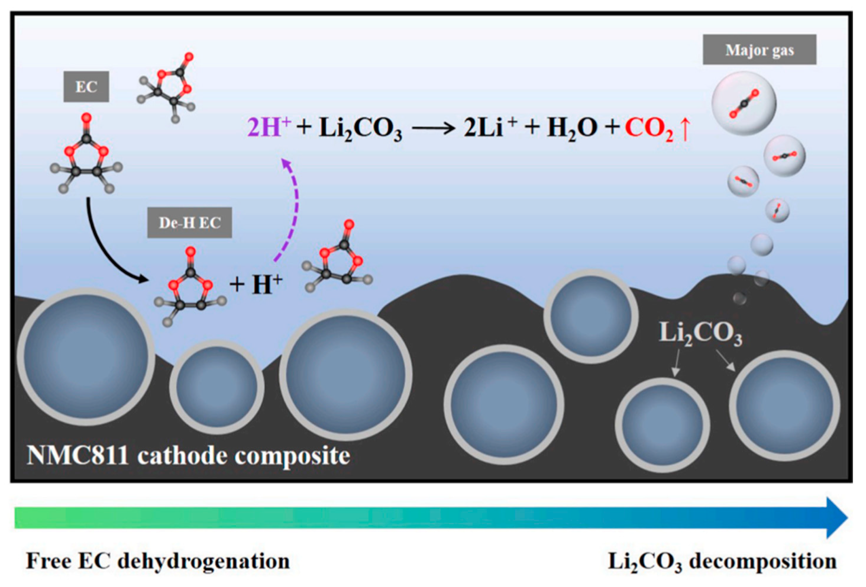
2.2. Electrode-Electrolyte Interface Instability

Surface electrode reactions with electrolytes are a significant factor contributing to capacity fading in Ni-rich cathode materials. Dissolution of transition metals, especially Ni and Mn, resulting from electrode–electrolyte interactions, affects both the cathode and anode materials in LIBs and eventually leads to electrochemical performance degradation by capacity fading and impedance increase [60,61,62,63,64]. S. J. Wachs et al. [65] conducted online monitoring to assess the dissolution of transition metals in NCM811. The researchers observed a significant increase in the concentration of transition metals in the electrolyte over time, particularly at high operating cutoff voltage. This phenomenon intensified with an extended duration of electrode polarization and through multiple charge-discharge cycles. A similar observation was made for NCM111, where the dissolution of transition metals, especially Mn, was detected at a high cutoff voltage [66]. D. Ko et al. [67] explored the correlation between cell impedance and the dissolution of transition metals in Li1.0Ni0.87Co0.09Mn0.04O2 cathode materials. Their investigation suggested that the hydrofluoric acid (HF), resulting from the interaction of a polyfluoroanion-based salt in the electrolyte with trace amounts of water or the breakdown of the organic electrolyte, ultimately contributed to the dissolution of transition metals. Consequently, the presence of H+ ions in the electrolyte instigated an attack on the electrode surface, leading to transition metal dissolution. This inference indirectly underscores that particles exhibiting greater microcracks are particularly prone to capacity deterioration, elucidating the adverse impact of microcrack generation and propagation on cathode materials. The backscattered electron image in Figure 9a illustrated the graphite surface after 500 cycles, with white areas indicating the deposition of elements heavier than carbon, such as transition metals. The electron probe microanalysis spectrum (Figure 9b) verified the presence of Ni on the anode surface. Notably, Co and Mn, due to their low concentrations, were undetected on the anode surface, contrasting with the clear presence of Ni (Figure 9c–f). The ion chromatograms graph in Figure 9g revealed that transition metals leaching from the cathode initiated from the second cycle reached concentrations of 2.56, 0.43, and 0.06 ppm for Ni, Co, and Mn, respectively. This leaching led to either deposition on the anode surface or the formation of transition-metal-containing polymerized organic matter in the electrolyte. J. A Gilbert et al. [68] suggested a model for mechanism cell impedance increase in NCM523/Gr where transition metals dissolve in the electrolyte and migrate to the SEI layer on the graphite, which changes its properties and traps more lithium. The explanation for the change in the SEI layer was provided, and Figure 9h can be helpful for better understanding. The capacity fading in high upper cutoff voltages is divided into three stages. In stage I, growth of SEI is a diffusion-controlled process in cutoff voltages lower than 4.3 V; however, when cutoff voltage increases above 4.30 V, a dramatic changeover occurs due to deterioration in an unpredictable, stochastic manner, and in the process, it loses a fraction of transition metals as ions. These ions subsequently migrate toward the negative electrode and become incorporated into SEI. After a relatively short induction period (stage I), deposition of these ions causes rapid growth of SEI with a rate that significantly exceeds the typical diffusion-controlled rates (stage II). Once this SEI grows sufficiently thick, a diffusion-controlled growth resumes at a new, higher rate (stage-III). In this state, further stress fracture of the oxide grains largely ceases due to the depletion of suitable sites. The alternative explanation is that oxide fracture continues, but it does not result in rapid SEI growth. The SEI coating becomes so thick that deposition of transition metals ions on its top does not result in more reduction of the material, as these deposited ions become separated from the reactive surface.
The safety and thermal abuse tolerance attributes of LIBs are serious concerns, particularly in EVs and large-scale applications. Within ternary Ni-based active material systems thermal stability is contingent upon the Ni concentration. At highly delithiated states, NCM and NCA cathode materials cause the reduction of Ni4+ during heating to release oxygen, initiating reactions with flammable electrolytes and leading to thermal runaway. Throughout the charging and overcharging cycling, the migration of Li+ ions from the bulk to the surface occurs, creating a concentration gradient between the core and the surface, resulting in non-uniform Li distribution within the particle. Determined by the lithium concentration in LixMO2, the material decomposes into layered, spinel, and rock-salt structures, accompanied by the release of oxygen. The relationship between O2 release reactions and the extent of delithiation in LixNiO2 can be understood by examining Reactions (1) and (2) [69,70]:
LixNiO2 (layered) = (1 − x)LiNi2O4 (spinel) + (2x − 1)LiNiO2 (layered), 0.5 < x < 1,
LixNiO2 (layered) = xLiNi2O4 (spinel) + (1 − 2x)NiO (rock salt) + ((1 − 2x)/2)O2, 0.5 > x
Bak et al. [71] delineated a specific path of phase transitions correlated with oxygen evolution in charged NixMnyCoz (x:y:z = 4:3:3, 5:3:2, 6:2:2, and 8:1:1) as a function of heating temperature. The authors verified that phase transition in NCM cathodes went from a layered structure at room temperature to a disordered LiMn2O4-type spinel at temperatures above 150 °C (depending on NCM chemistry). A subsequent transition to a new spinel structure—assigned as a M3O4-type spinel (such as Co3O4 with Fd-3m space group)—and a rock-salt structure occurred at elevated temperatures. The primary distinction between the two spinel structures lay in cation occupations, particularly at the 8a tetrahedral sites. In the first spinel structure, Li occupies the 8a tetrahedral sites, while in the latter, transition metal cations migrate to these sites. Notably, the formation of the M3O4-type spinel delayed the formation of the rock-salt structure to a higher temperature, resulting in improved thermal stability [72]. As illustrated in Figure 10a, the phase transition to spinel structures occurred at lower temperatures, with a slight increase in Ni, indicating fewer transition metal migrations to 8a tetrahedral sites in NCM samples with less than 50% Ni. It is evident that the rock-salt structure formed at 365 °C and 550 °C in NCM811 and NCM622, respectively, while no rock-salt formation was observed for the other two samples up to 600 °C. Interestingly, O2 release aligned with phase transitions in all samples. Considering O2 release and phase transition, Figure 10b confirmed that in higher Ni content, the onset and range of temperature for O2 release were lower and narrower, respectively. Figure 10c explicitly elucidates the mechanism of phase transition in charged NCM during heating. Initially, transition metal cations occupied the octahedral layer, while Li+ ions were situated in alternate layers of octahedral sites. The first phase transition from layered to disordered occurred as transition metal ions migrated through favorable tetrahedral sites due to a lower energy barrier [73,74]. In this step, Li ions occupied tetrahedral sites, and a LiMn2O4-type spinel was formed. At high temperatures, a phase transition to a M3O4-type spinel structure transpired due to partial transition metal occupation in 8a tetrahedral sites. Due to the high stability and different electronic configurations of Co2+ and the instability of Ni2+ in tetrahedral sites, Ni ions preferentially occupied octahedral sites [75]. This explanation underscores the role of the Ni:Co:Mn molar ratio in the thermal stability of NCM cathodes. With lower Co concentration in NCM811, and consequently rapid Co cation migration to tetrahedral sites, the LiMn2O4-type spinel phase transition occurred rapidly at lower temperatures, and the temperature range for the thermally stable M3O4-type spinel type was narrower. It was suggested that NCM532 was the optimized sample from the thermal stability perspective and higher Mn content in the surface effectively increased thermal stability behavior of NCM materials. As explained earlier, the presence of NiO with a rock-salt structure at the cathode surface results in an increase in impedance during cycling, leading to degradation in the cycle capacity and thermal stability of the battery [71,76]. L. Wu et al. [76] conducted thermodynamic principle calculations based on oxidation and enthalpy reactions (Reaction (3) and Equation (1)) to elucidate the preferential formation of a rock-salt structure on the particle surface in Ni-rich cathodes:
2MO2 (layered) = 2MO (rock-salt) + O2,
ΔH = 2E (MO) + E(O2) + 2E (MO2)
A negative enthalpy indicates that the decomposition of MO2 to rock-salt MO with the release of O2 is exothermic, signifying that the MO structure is more stable. In contrast, for positive enthalpy, MO2 is more stable than MO. The average reaction enthalpy is −0.8 eV and 1 eV per O2 for Ni0.8Co0.2O2 and Ni1/3Co1/3Mn1/3O2, respectively. This indicates that it is thermodynamically stable to form rock-salt in Ni-rich cathodes, and the MO structure is energetically favorable. It is noteworthy that the energy required to decompose MnO2, CoO2, and NiO2 to rock-salt is approximately 3 eV/O2, 1.7 eV/O2, and −1.5 eV/O2, respectively. These values clarify why Ni-enriched cathodes, such as LiNiO2, are thermally unstable compared to NCM111. Therefore, to enhance the thermal stability of Ni-based materials, it is suggested to increase Mn concentration at the surface of particles and Ni in the bulk.
Structural transformations during the heat treatment, including R-3m → Fd-3m and Fd-3m → Fm-3m, were observed in delithiated NCM111 and Ni0.8Co0.15Al0.05, where O2 release and thermal decomposition occurred at a lower temperature for NCA compared to NCM111. Differential scanning calorimetry (DSC) showed exothermic peaks (Figure 11a,b) for both cathodes and electrolyte reaction, while NCM111 had higher onset temperature (beyond 300 °C) and lower heat generation, at 790 J g−1 compared to NCA (250 °C and 1460 J g−1) [77]. TGA substantiated the release of O2 at elevated temperatures for both cathodes, albeit with varying quantities. The thermogravimetric analysis (TGA) profiles (Figure 11c) depicted alterations in the weight of delithiated samples, indicating O2 loss from the lattice structure. The structural instability of NCA is evident, leading to O2 release at lower temperatures and a higher mass loss compared to NCM111—11% and 6% at 600 °C, respectively [78]. Time-resolved XRD (TR-XRD) is a powerful technique to afford researchers a better understanding of structural changes in active materials. TR-XRD patterns of overcharged NCM111 and Ni0.8Co0.15Al0.05 revealed that, in accordance with DSC and TGA profiles, the starting and completion points of phase transition are at 216 °C and 212 °C, and 337 °C and 256 °C, respectively. By heating up to 400 °C, another spinel phase was observed for NCA, while there was nothing for NCM111. As mentioned before, the formation of an M3O4-type spinel structure pushes formation of the rock-salt structure [72].
Organic carbonates, particularly ethylene carbonate (EC), and various linear carbonates, such as dimethyl carbonate (DMC), ethyl methyl carbonate (EMC), and diethyl carbonate (DEC), serve as the primary electrolyte components in LIBs [79]. The cathode surface of charged Ni-rich compositions exhibits a higher propensity for releasing reactive oxygen compared to other compositions, posing a significant safety risk. The released oxygen can potentially react violently with the flammable electrolytes within the battery, thereby risking a catastrophic explosion [80,81,82]. Furthermore, significant CO and CO2 gas formation ensues due to the decomposition of the electrolyte, reactions with impurities in the cell, or the release of gases trapped inside the particle. This phenomenon induces an increase in internal pressure, leading to mechanical stress within the electrodes and localized fractures. Notably, this occurrence was observed at lower cell potentials, approximately around 4.2 V (vs graphite), for NCM811, whereas it became apparent at 4.6 V for both NCM111 and 622 [83,84,85].
Upon lithium extraction in NCM materials, the c-parameter increases until roughly 2/3 of the lithium is removed. This increase is attributed to repulsive interactions of negatively charged oxygen layers upon the removal of positive Li ions. O2 evolution from NCM cathode materials correlates with the SOC (Li removal), indicating an increased instability at high degrees of delithiation. Generally, O2 evolution initiates at a critical SOC of about 80% for all layered active materials, irrespective of the potential at which this SOC is reached. However, Ni-rich materials reach the critical SOC at lower potentials due to their flatter potential profile. Subsequent Li removal at higher SOC results in a decreasing c-parameter, linked to increasing covalency between the metal and oxygen. This covalency corresponds to a decrease in the oxygen anion charge density, exemplified by the oxidation of lattice oxygen anions. Upon reaching the critical SOC of about 80%, the evolution of singlet oxygen is a chemical reaction of the electrode material, directly or indirectly caused by Li deficiency, leading to the loss of lattice oxygen as enough lithium is removed to destabilize the crystal structure. The H2 → H3 phase transition occurred in high levels of SOC at about 4.2 V; Li/Li+ is hypothesized to contribute to the shrinkage of the c-parameter for NCM811, and this phenomenon could result from decreasing repulsion between the oxygen layers caused by the oxidation of oxygen anions, ultimately leading to O2 release [54,86]. The O2 release is the catalyst for the generation of CO and CO2 within battery cells. CO2, a widely recognized byproduct, arises from the irreversible oxidation of carbonate solvents employed in battery electrolytes. Illustrated in Figure 12a, the potential for EC oxidation primarily resides in the two carbon atoms bound to hydrogen, as the carbonyl-carbon is already in its maximum oxidation state. The underlying mechanism initiates an electrophilic attack on the carbon by the O2 molecule, leading to the formation of a peroxo group carrying the proton initially bound to the carbon. This relatively unstable peroxo group undergoes immediate decomposition, resulting in the formation of a carbonyl group and the release of a water molecule. Subsequent decomposition of this molecule has the potential to yield CO, CO2, and formaldehyde. Reaction (4) encapsulating this process is represented as follows [54]:
EC + 2O2 (lattice) = 2CO2 + CO + 2H2O
O2 release is responsible for the generation of CO and CO2 in battery cells due to reaction with other organic carbonates. CO and CO2 gassing with a reduced ratio compared to EC were observed in the reaction of EMC and reactive oxygen release from NCM811 by W. M. Dose et al. [87]. EMC decomposition pathways to ethanol, CO2, and CO were proposed, considering its chemical and electrochemical instability in the presence of reactive lattice oxygen [87]. The proposed pathways for EMC decomposition to ethanol and the production of CO2 and CO are illustrated in Figure 12b, and is represented as Reaction (5). Considering the chemical and electrochemical instability of ethanol in the presence of reactive lattice oxygen, multiple pathways for oxidation of ethanol to acetaldehyde and either peroxide or protons are possible, as shown in Figure 12c [87].
EMC + O2 (lattice) = EtOH + CO2 + CO + H2O
Furthermore, water produced by the decomposition of EC and EMC contributes to further degradation. The reaction of nucleophilic attack by water with aldehydes may lead to acetal formation (Figure 12d). Additionally, LiPF6 decomposition is more likely in the concomitant presence of water and protons, leading to capacity fading and promoting higher concentrations of acidity and proticity that can migrate to the negative surface and degrade the solid electrolyte interface layer (Figure 12e) [88]. DMC is highly prone to hydrolyzation compared to EC. The intermediate products of DMC hydrolysis, formic acid and lithium methyl carbonate (LMC), undergo further chemical oxidation, forming formic acid, water, and CO2 (Figure 12f) [89,90].
Figure 12. (a) Proposed mechanism for the oxidation of EC with reactive oxygen released from the NCM structure and yielding CO2, CO, and H2O. Reprinted from Ref. [54] with permission from ECS. (b) Hypothesized mechanism illustrating the chemical oxidation of EMC and the production of CO2, CO, and H2O, (c) comparative analysis of chemical and electrochemical oxidation routes for the conversion of alcohols to aldehydes, (d) illustration of nucleophilic attack on aldehydes by water or alcohols, resulting in the formation of acetals, (e) visualization of the decomposition process of LiPF6 salt. Reprinted from Ref. [87] with permission from American Chemical Society. (f) Proposed reaction scheme depicting the chemical oxidation of DMC leading to the formation of formic acid, CO2, and Water. Reprinted from Ref. [90] with permission from the American Chemical Society.
Materials 17 00801 g012
Excess Li is typically used in Ni-rich cathode materials to decrease Li/Ni cation mixing, aiding in obtaining a well-ordered layer structure. However, Li2O remains at the surface, and LiOH and Li2CO3 impurities form easily during preparation and storage due to the slow and spontaneous reduction of Ni3+ to Ni2+. The presence of residual lithium compounds is unfavorable, as they cause unwanted side reactions through oxidative decomposition of LiOH and Li2CO3 at high voltages, resulting in irreversible capacity. The formation of Li2CO3 is presumed to take place via Reaction (6). In the case of Li(NiCoAl)O2 electrode materials, these compounds are prone to reaction with CO2 and moisture in the air [91,92,93,94,95].
Li(NiCoAl)O2 + 1/4xO2 + 1/2xCO2 = Li1−x(NiCoAl)O2 + 1/2xLi2CO3
The performance of active materials deteriorates, as LiOH increases the pH during electrode processing, causing gelation [96]. Additionally, Li2CO3 causes gas generation and cell swelling, potentially leading to safety issues in LIBs [97]. In a worse scenario, acidic HF forms as a result of the reaction between LiOH and LiPF6 in the electrolyte. This leads to transition metal dissolution at the charged state, water and CO2 gas evolution, formation of an insulating surface layer, and phase transition to a spinel structure [92,98,99,100]. CO2 outgassing by Li2CO3 decomposition may occur through possible pathways, including an electrochemical process in which Li2CO3 can decompose near its standard potential, E° = 3.82 V vs. Li/Li+, with Reaction (7). Although Kaufman et al. [101] claimed that that the electrochemical decomposition of Li2CO3 did not necessarily generate oxygen gas, the production of a reactive oxygen species is possible, and these species can directly or indirectly participate in electrolyte degradation processes [102,103].
2Li2CO3 = 4Li+ + 4e + 2CO2 + O2
It is also suggested that an increase in free EC concentration near the oxide cathode surface, easily adsorbed due to its higher dielectric constant compared to commonly used linear alkyl carbonate, facilitates the decomposition of Li2CO3 (Reactions (8) and (9)), as illustrated in Figure 13 [104].
EC (free) = De–HEC + H+ + e,
Li2CO3 + 2H+ = 2Li+ + H2O(l) + CO2(g)

3. Strategies and Countermeasures

Extensive research has been undertaken to enhance Ni-rich cathode materials performance in response to the growing demand for batteries with higher energy density. Common strategies employed for this purpose include elemental substitution, surface treatment, compositional adjustments, as well as the utilization of single crystals and concentration gradient structures. These methods are widely adopted to address the associated challenges and requirements effectively.

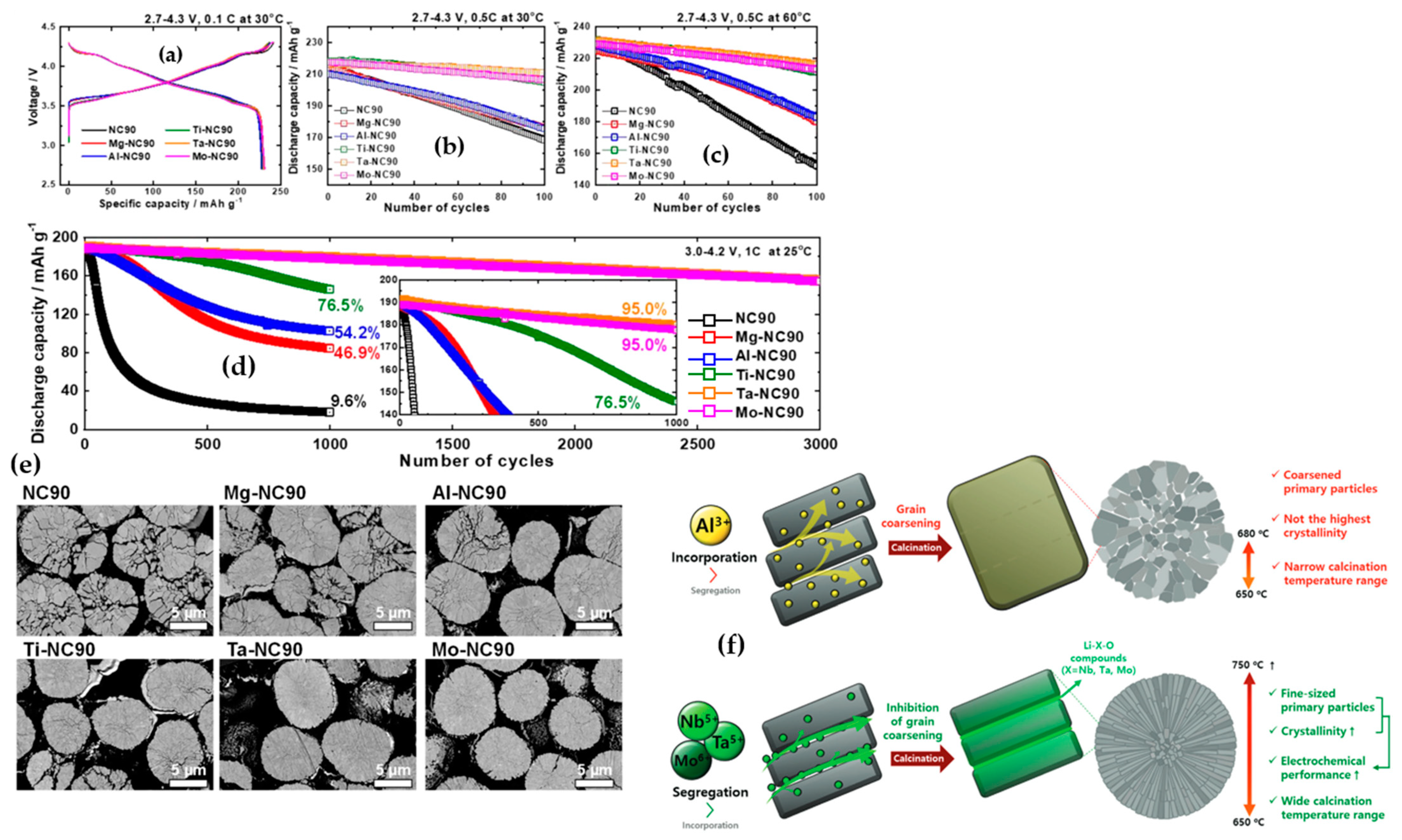
3.1. Elemental Doping

The incorporation of cation and anion doping has emerged as a prominent strategy to enhance the structural stability of Ni-enriched layered oxides [105,106]. This approach proves pivotal in improving the cycling performance of cathode materials by substituting unstable elements with inactive materials. It effectively hinders microcrack propagation within primary particles through the pillaring effect of cationic species, while stabilizing the oxygen octahedral site through anionic doping [107,108]. As an example, Mg emerged as a promising cation element with the potential to serve as an inert stabilizer, leading to enhanced performance in NCM622 cathode materials by mitigating structural deterioration. The introduction of Mg at concentrations of 1%, 3%, and 5% resulted in a reduction of Li/Ni cation intermixing by 1.58%, 1.77%, and 3.20%, respectively, compared to the 5.18% observed in undoped NCM. When Mg ions partially substituted for Ni in Mg-doped NCM, the unit cell parameters a and c decreased in magnitude, while the c/a ratios increased. This change typically signified the development of a layered material structure. The reduction in unit cell dimensions a and c was attributed to the incorporation of Mg2+ ions into both the Li layer and the transition metal layer. This incorporation led to a decrease in the overall content of Ni2+ ions residing within the Li layer. This phenomenon is comprehensible because the diminished presence of Ni2+ ions in the structure of Mg-doped powders resulted in a slight reduction in lattice parameters. Furthermore, it is noteworthy that the bond dissociation energy of Mg-O (∆Hf298 = 394 kJ mol−1) surpasses that of Ni-O (∆Hf298 = 391 kJ mol−1). Therefore, the introduction of Mg2+ ions into the host structure contributed to the enhancement of structural stability [109]. Anionic dopants, like F, have the capacity to occupy oxygen sites without compromising the capacity and energy density of the active materials. Among these anionic dopants, fluorine exhibits the highest electronegativity and establishes a remarkably stable structure due to the formidable bonds formed between transition metals and fluorine. Furthermore, the enhanced electrochemical performance of cathode materials doped with fluorine may be attributed to their shielding effect against HF production, which can arise during the decomposition of the liquid electrolyte [110,111,112]. Sung-Beom Kim et al. [113] employed a solid-state reaction method to synthesize F-doped NCM811. The pristine material exhibited a discharge capacity of 97.9 mAh g−1 after 100 cycles at a rate of 100 mA g−1, within the voltage range of 2.8–4.3 V. In contrast, the discharge capacities of LiNi0.8Co0.1Mn0.1O2−xFx, with x values of 0.02, 0.04, 0.06, and 0.08, were measured at 107.8, 133.2, 169.6, and 154.5 mAh g−1, respectively. Furthermore, assessing the capacity retention of various samples, including NCM-bare, NCMF-2, NCMF-4, NCMF-6, and NCMF-8 after 100 cycles, revealed retention percentages of 60.7%, 66.2%, 78.8%, 96.8%, and 89.5%, respectively. A diverse array of elements has been successfully employed as cation and anion dopants for transition metals and oxygen sites, aiming to enhance the electrochemical performance of Ni-rich cathode materials. Notable examples include Mo [114,115], Al [116,117], B [118], Nb [119,120,121], K [122], Na [123], Mg [109], Ti [124,125,126,127,128,129,130], PO43- [131], and F [113,132,133]. It is worth mentioning that doping Ni-rich cathode materials with cations of varying valence states engenders distinct mechanisms that contribute to performance enhancement. Figure 14a–d provides a visual representation of the electrochemical effects resulting from a 1% molar elemental doping with diverse valence states on LiNi0.91Co0.09O2 active material [134]. Notably, all doped materials, irrespective of low valence (Mg2+ and Al3+) or high valence (Ti4+, Ta5+, and Mo6+) states, exhibited superior electrochemical performance compared to the undoped counterpart in initial cycles, regardless of cycling rate and temperature. While samples doped with low valence states displayed satisfactory performance over extended cycles, such as 1000 cycles, capacity retention significantly decreased to 54.2% and 46.9% for Al and Mg-doped samples, respectively. In contrast, Ta- and Mo-doped samples maintained capacity retention even after 3000 cycles. Structural evaluations of samples, depicted in cross-sectional SEM images (Figure 14e) of cathodes cycled up to 1000 cycles, revealed that undoped NC90 exhibited severe intergranular cracks and disintegration into individual grains. Conversely, Mg and Al-doped samples showed incipient microcrack propagation, while Ta and Mo-doped samples retained particle coherency with minimal signs of microcrack nucleation and propagation, aligning with their exceptional cycling stabilities. These observations suggest diverse mechanisms contributing to the enhancement of doped samples.
Park et al. [135] have proposed mechanisms for improvement through cation doping with different valence states (Figure 14f). The authors investigated the effects of a 1% molar doping of Al3+, Nb5+, Ta5+, and Mo6+ in LiNiO2. They suggested that cations with low valence states, such as Al3+, participated in the bulk and acted as pillars to improve structural stability and electrochemical performance. Regarding high valence cations, such as Mo6+, Nb5+, and Ta5+, these elements not only participated in the bulk structure, but also reacted with Li resources and Li-X-O compounds forming and segregating at grain boundaries, inhibiting grain boundary migration, and preserving the size of primary particles. For instance, Al 1% molar doping in LiNiO2 resulted in LiAlO2 formation at 650 °C, disappearing at 680 °C. In contrast, compounds such as LiNbO3 appeared at low temperatures, and at higher calcination temperatures, the insoluble Li3NbO4 phase were segregated in the grain boundaries. Consequently, if doping elements persisted as Li-X-O compounds during high-temperature calcination, they coated the grain boundary, inhibiting boundary migration and suppressing primary particle coarsening. For elements like Al and Mg with low valence states, it was suggested that higher doping molar concentrations (3%) could be beneficial for grain boundary reinforcement. In a study by Hüger et al. [136], it was revealed that compounds like LiNbO3 and LiTaO3 exhibit higher Li diffusivity, or in other words, had a higher Li insertion/extraction rate (about 1 × 10⁻¹⁸ and 8 × 10⁻¹⁹ m2 s−1, respectively) compared to other compounds such as LiAlO2 and LiGaO2 (about 4 × 10⁻²¹ and 1 × 10⁻²¹ m2 s−1, respectively). Furthermore, the bond dissociation energy of Nb-O and Ta-O is nearly twice (∆Hf298 = 753 and 805 kJ mol−1, respectively) that of Mg-O and Ni-O, thereby enhancing structural stability. The published works in recent years on the doping of Ni-rich cathode materials are summarized in Table 3.

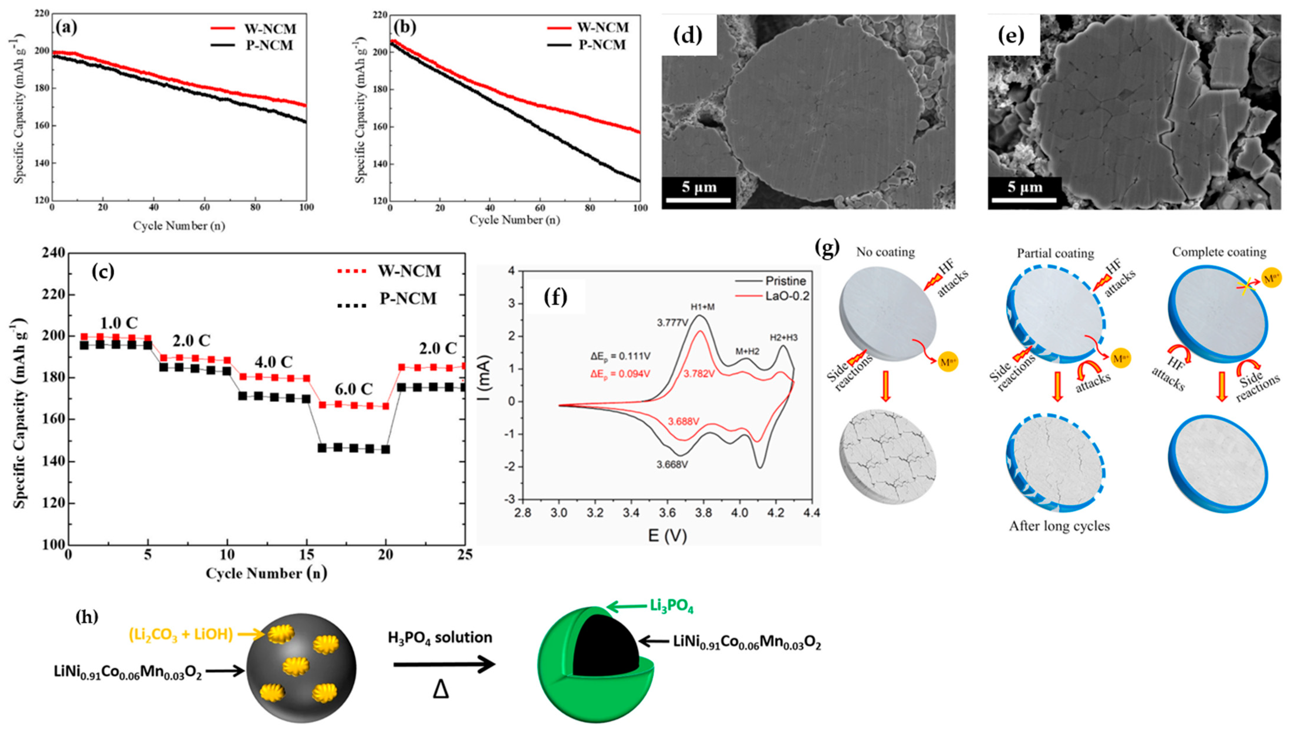
3.2. Surface Coating

Surface treatment represents a foremost strategy to mitigate interfacial side reactions between cathode materials surface and electrolytes, with the aim of enhancing the retention of oxide ion vacancies within the crystal lattice post-initial charge. This approach concurrently addresses challenges such as the suppression of electrolyte decomposition, the mitigation of cathode-electrolyte interphase formation, the preservation of low microstrain for improved structural integrity and crystallinity during cycling, and the sequestration of HF from the electrolyte [154,155,156,157,158]. In the context of Ni-rich materials, a coating which is generally composed of nanoparticles and typically ranging from 5–20 nm can be broadly classified into three categories: oxides, phosphates, and fluorides. Among these, metal oxide coatings, including Al2O3 [159], Li4Ti5O12 [160], ZrO2 [161,162], Li2WO4 [163], and Li2ZrO3 [164] have emerged as widely adopted choices to address the limitations of Ni-rich materials. Shim et al. [165] specifically applied an acidic WO3 coating to NCM811 particles, leveraging its intercalation host properties attributed to its well-defined cubic ReO3-type structure and high resistance against HF attack. As depicted in Figure 15a,b, the WO3 coating significantly enhanced the cycling performance of NCM811 within the 3–4.3 V range, and notably, under challenging conditions spanning a voltage range of 3–4.6 V. The capacity retention of the pristine active material at upper cutoff voltages of 4.3 V and 4.6V was 82% and 64.44%, respectively, while for the WO3-coated NCM811, the corresponding values were 85.8% and 76.46%, respectively. In terms of rate capability performance (Figure 15c), the coated sample exhibited superior performance attributed to expedited Li ion and electron kinetics, stemming from enhanced structural stability and reduced resistance. This improvement was further attributed to the suppression of side reactions between the cathode material and electrolyte. Moreover, Figure 15d,e illustrates the absence of discernible microcracks along grain boundaries in NCM protected by a 2.14 nm thick WO3 coating. In contrast, the untreated NCM, subjected to cycling-induced expansion and shrinkage, exhibited electrolyte infiltration into the interior, leading to structural collapse. This observation underscored the effectiveness of the WO3 coating in preserving the structural integrity of NCM during cycling. The incorporation of a La2O3 coating as a protective layer has proven highly effective in augmenting the electrochemical performance of the Ni0.91Co0.06Mn0.03 electrode in LIB [166]. Notably, the capacity retention of the cathode after 100 cycles at 0.5C demonstrated a substantial improvement, with a retention rate of 68.1% for the pristine NCM, whereas the La2O3-coated material exhibited superior retention at 87.2%. The cyclic voltammetry plots (Figure 15f) of both pristine and coated samples revealed significant improvements by coating deposition on NCM material. First, the intensity peak related to phase transformation H2 → H3 that is in charge of particle pulverization and capacity fading decreased significantly. Secondly, the oxidation-reduction gap (ΔE = Eoxidation − Ereduction), which serves as a determinant of electrode polarization, reduced from 0.111 V to 0.094 V [165]. A TiO2 coating was employed to provide comprehensive protection for NCM811 cathode active materials, capitalizing on its structural stability and chemical inertness against the electrolyte at high voltages [167]. Q. Fan et al. [167] reported that the application of a continuous TiO2 nano-coating layer on NCM811 not only resulted in a higher specific discharge capacity, but also significantly improved cycling performance, with 72.2% capacity retention for the coated sample and 45.7% for the bare sample. This improvement was attributed to the reduction in side reactions at the electrode and electrolyte interface, particularly at high upper cut-off voltages. The exceptional barrier properties of the TiO2 coating led to a reduction in electrolyte consumption and the formation of a thick passivation solid electrolyte film. This reduction helped alleviate polarization at the material interface, preventing the inevitable damage resulting from direct contact between the active material and the electrolyte. Figure 15g illustrated a schematic representation of the protective mechanism of TiO2, emphasizing the significance of an intact coating for active materials. This depiction underscores that the development of a partial coating may result in the isolation failure of particles, potentially leading to the collapse of secondary particles. Phosphate coatings have emerged as highly protective coatings for matrix materials, acclaimed for their exceptional thermal and electrochemical stability. This stability arises from the robust P=O bond, with a bond energy of 5.64 eV and the formation of strong covalent bonds between polyanions and metal ions, rendering them resistant to chemical attacks [168,169,170,171]. Among phosphate coatings, the Li3PO4 coating stands out as a prominent choice for Ni-rich active materials due to its rapid Li+ conductivity and high chemical stability [172]. The wet-coating method, utilizing an aqueous solution of NH4H2PO4 or phosphoric acid, has been widely employed to extensively create Li3PO4 coatings on active materials, enabling a substantial reduction of lithium-based surface impurities (LiOH and Li2CO3) and the suppression of detrimental side reactions during both storage and cycling [173,174]. T. Sattar et al. [175] coated Li3PO4 onto layered oxide Ni0.91Co0.06Mn0.03 active material by transforming Li residual compounds into the coating (Figure 15h). The superior electrochemical rating and cycling performance of the coated samples were attributed to the removal of lithium residual compounds and the isolation of particles, preventing direct contact with the electrolyte and excessive growth of the solid electrolyte interface layer. Additionally, the higher dissociation energy bond of P=O compared to transition metal–oxygen bonds contributed to better electrochemical performance, with capacity retention rates of 68.1% for pristine NCM and 82.4% for the surface-modified sample. In the context of EV industries, where thermal stability is crucial, Ni0.8Co0.15Al0.05 cathode materials, employed in Tesla’s Model S and X, have gained prominence [176]. A Li3PO4 coating developed on Ni0.815Co0.15Al0.035 active material has been shown to decrease heat generation during cycling. A study conducted by Tang et al. [177] confirmed through DSC profiles that the Li3PO4-modified samples generated less heat (525 J g−1) compared to the pristine sample (757 J g−1), highlighting the efficacy of the coating in suppressing surface side reactions with the organic electrolyte. The entire process of reaction between Li residual compounds and phosphoric acid can be expressed through the following Reactions (10)–(12) [178,179]:
3Li2O + 2H3PO4 = 2Li3PO4 + 3H2O,
3LiOH + H3PO4 = Li3PO4 + 3H2O,
3Li2CO3 + 2H3PO4 = 2Li3PO4 + 3H2O + 3CO2
Fluorides exhibit lower Gibbs energy compared to oxides, indicating their heightened stability in comparison to oxide counterparts. The utilization of metal fluorides as protective coatings has been extensively investigated to address challenges associated with electrode side parasitic reactions with the electrolyte and HF etching. Among the various fluorine coatings, LiF is frequently employed for Ni-rich active materials. A thermodynamically stable lithium fluoride coating, characterized by superior Li ion conductivity compared to other fluorides, has been typically achieved through the mixing of NH4F and NH4HF2 with the original cathode materials [180,181]. H. Kim et al. [182] treated Ni0.85Co0.12Al0.03 cathode material with NH4HF2 and reported that this treatment helped to remove Li residual compounds from the particles’ surface and additionally, both cycling performance and gas evolution behavior were enhanced significantly in the modified sample.
The published works in recent years on the coating development of Ni-rich cathode materials are summarized in Table 4.

3.3. Structural Engineering

The innovative approach to developing functional layered oxide materials involves creating a comprehensive concentration gradient structure. This strategy utilizes a high-capacity Ni-rich core in conjunction with a chemically stable Co, Mn-rich surface to prevent undesired Ni4+ reduction on the material’s surface. In a typical cathode with a full concentration gradient, the concentration of Ni gradually decreases from the particle’s center to its outer surface, while the concentrations of Co and Mn increase [198]. Hou et al. [199] synthesized a full concentration gradient (FCG) NCM622 with LiNi0.8Co0.2O2 for the inner composition, and LiNi0.4Co0.2Mn0.4O2 for the outer composition. Reports indicated that the FCG-NCM622 cathode exhibited superior capacity retention at both room temperature and 55 °C. Moreover, DSC analysis confirmed the enhanced thermal stability of the structurally modified NCM622 compared to the normal sample. The exothermic peak observed at 282.7 °C for FCG-NCM622 and 266.2 °C for NCM622 indicated better thermal stability for the former. The generated heat was 692 J g−1 for FCG-NCM622 and 969 J g−1 for NCM622, attributed to the presence of Mn on the outer surface of the active material. Recently, a combination of FCG and coating-doping modifications has been employed to improve the thermal and electrochemical performance of Ni-enriched cathode materials [200,201]. Liao et al. [202] utilized dual modification for NCM material, incorporating both a concentration gradient and a protective Al2O3 coating. Figure 16a–c demonstrates that this dual modification significantly enhanced electrochemical performance, resulting in lower voltage decay over cycling compared to a normal cathode. This improvement was attributed to the reduced reaction of the cathode material with the electrolyte, and higher structural stability. The capacity retention for coated CG-NCM after 100 cycles was approximately 88%, outperforming CG (80%) and normal NCM (62.6%) as shown in Figure 16d. The impact of dual modification became more evident in cycling at higher temperatures (55 °C), as illustrated in Figure 16e. In terms of thermal stability, DSC profiles (Figure 16f) confirmed that both coated CG and CG samples exhibit a higher onset temperature for the exothermic reaction compared to the normal sample, indicating the effectiveness of both modifications. Park et al. [203] explored the electrochemical and thermal characteristics of a concentration gradient Ni0.865Co0.120Al0.015 cathode material. Although conventional NCA demonstrated a slightly higher initial discharge capacity at 0.1C in the operating potential range of 2.7–4.3 V compared to CG NCA (225 and 222 mAh g−1, respectively), the capacity retention of the CG electrode at 0.5C, both at room temperature and 60 °C, was notably superior to that of the standard sample. Moreover, differential scanning calorimetry (DSC) measurements on charged samples at 4.3 V revealed an exothermic peak at 192 °C with a heat generation of 1789 J g−1 for conventionally synthesized NCA, whereas for CG NCA, it was observed at 202 °C with a lower heat generation of 1409 J g−1, indicating enhanced thermal stability of the structurally modified NCA. Xu et al. [204] successfully synthesized a concentration gradient cathode material comprising Ni0.7Co0.13Mn0.17 with NCM811 composition at the core and NCM523 at the outer surface (Figure 17a–e). The initial charge–discharge profile (Figure 17f) of NCM523, NCM811, and the CG NCM indicated that the CG sample exhibited a lower discharge capacity compared to NCM811, attributed to its lower Ni content on the surface. Additionally, the plateau at around 4.2 V was shorter for NCM523 and CG compared to NCM811. Moreover, the H2 → H3 phase transition, recognized as the primary reason for volume change and subsequent capacity fading in Ni-rich electrodes, was pronounced for NCM811 compared to the CG cathode material (Figure 17g). The rate capability of the CG electrode outperformed that of NCM811 and NCM523 counterparts, delivering much higher capacity at high discharge rates (Figure 17h). Cycling profiles of the samples at 1C (Figure 17i) revealed that NCM811 experienced catastrophic capacity retention, while the performance of CG was highly similar to that of NCM523. These results suggest that utilizing the CG cathode offers benefits for both NCM523 in terms of capacity retention, and for NCM811 in terms of high capacity delivery.

4. Conclusions and Perspectives

Lithium-ion batteries are indispensable for meeting the surging demand for renewable energy solutions, offering high energy density, extended cycle life, and safety. Among materials for cathode in LIBs, Ni-enriched cathode materials stand out for their remarkable capacity and energy density, positioning them as promising contenders for future battery applications.
This review delineates the key hurdles hindering the widespread integration of Ni-rich cathode materials in electric vehicles (EVs). Structural instability and side reactions pose significant challenges, categorized into phase transitions, microcrack formation, cation mixing, and gas release. Various strategies, including elemental doping and surface coatings, are explored for enhancing battery lifespan and safety. Notably, the concentration gradient method emerges as a novel approach to bolster the performance of Ni-rich electrodes. However, further research is imperative, particularly in comprehending capacity fading mechanisms and optimizing modification techniques. Continuous investigation is essential to propel Ni-rich cathode materials towards widespread adoption in EVs and large-scale energy storage systems.

Author Contributions

Conceptualization, M.A.; methodology, J.L.; writing—original draft M.A.; writing—review and editing, B.S.; analysis and supervision, H.L. and M.Z. All authors have read and agreed to the published version of the manuscript.

Funding

The research was funded by National Science Foundations: NSF—OIA—2119688, NSF—MRI—2215982 and NSF—MRI—2216473.

Institutional Review Board Statement

Not applicable.

Informed Consent Statement

Not applicable.

Data Availability Statement

No new data were created or analyzed in this study. Data sharing is not applicable to this article.

Conflicts of Interest

The authors declare no conflicts of interest.

References

  1. Koo, J.K.; Choi, H.; Seo, J.K.; Hwang, S.M.; Lee, J.; Kim, Y.J. Microstructure engineering of nickel-rich oxide/carbon composite cathodes for fast charging of lithium-ion batteries. Ceram. Int. 2022, 48, 31859–31865. [Google Scholar] [CrossRef]
  2. Rudnicka, E.; Jakobczyk, P.; Lewandowski, A. Thermodynamic and kinetic limits of Li-ion battery operation. J. Energy Storage 2022, 55, 105747. [Google Scholar] [CrossRef]
  3. Entwistle, T.; Sanchez-Perez, E.; Murray, G.J. Co-precipitation synthesis of nickel-rich cathodes for Li-ion batteries. Energy Rep. 2022, 8, 67–73. [Google Scholar] [CrossRef]
  4. Chen, Z.; Danilov, D.L.; Rajimakers, L.H.J. Overpotential analysis of graphite-based Li-ion batteries seen from a porous electrode modeling perspective. J. Power Sources 2021, 509, 230345. [Google Scholar] [CrossRef]
  5. Zheng, H.; Li, J.; Song, X.; Liu, L.; Battaglia, V.S. A comprehensive understanding of electrode thickness effects on the electrochemical performances of Li-ion battery cathodes. Electrochim. Acta 2012, 71, 258–265. [Google Scholar] [CrossRef]
  6. Xie, Y.; Jin, Y.; Xiang, L. Li-rich layered oxides: Structure, capacity and voltage fading mechanisms and solving strategies. Particuology 2022, 61, 1–10. [Google Scholar] [CrossRef]
  7. Gamble, F.; Osiecki, J.H.; Cais, M.; Pisharody, R.; Disalvo, F.J.; Geballe, T.H. Intercalation complexes of Lewis bases and layered sulfides: A large class of new superconductors. J. Sci. 1971, 174, 493–497. [Google Scholar] [CrossRef] [PubMed]
  8. Tang, Z.; Wang, S.; Liao, J.; Wang, S.; He, X.; Pan, B.; He, H.; Chen, C. Facilitating lithium-ion diffusion in layered cathode materials by introducing Li+/Ni2+ antisite defects for high-rate Li-ion batteries. Res. J. 2019, 2019, 2198906. [Google Scholar] [CrossRef]
  9. Huang, D.; Engtrakul, C.; Nanayakkara, S.; Mulder, D.W.; Han, S.D.; Zhou, M.; Luo, H.; Tenent, R.C. Understanding degradation at the lithium-ion battery cathode/electrolyte interface: Connecting transition-metal dissolution mechanisms to electrolyte composition. ACS Appl. Mater. Interfaces 2021, 13, 11930–11939. [Google Scholar] [CrossRef] [PubMed]
  10. Deng, J.; Bae, C.; Denlinger, A.; Miller, T. Electric vehicles batteries: Requirements and challenges. Joule 2020, 4, 511–515. [Google Scholar] [CrossRef]
  11. Masias, A.; Marcicki, J.; Paxton, W.A. Opportunities and challenges of lithium ion batteries in automotive applications. ACS Energy Lett. 2021, 6, 621–630. [Google Scholar] [CrossRef]
  12. Jiang, M.; Qian Zhang, Q.; Wu, X.; Chen, Z.; Danilov, D.L.; Eichel, R.; Notte, P.H.L. Synthesis of Ni-rich layered-oxide nanomaterials with enhanced Li-ion diffusion pathways as high-rate cathodes for Li-ion batteries. ACS Appl. Energy Mater. 2020, 3, 6583–6590. [Google Scholar] [CrossRef]
  13. Manthiram, A. An outlook on lithium ion battery technology. ACS Cent. Sci. 2017, 3, 1063–1069. [Google Scholar]
  14. Zaghib, K.; Mauger, A.; Julien, C.M. Olivine-based cathode materials In Rechargeable Batteries. Green Energy Technol. 2015, 25–65. [Google Scholar] [CrossRef]
  15. Julien, C.M.; Mauger, A.; Zaghib, K.; Groult, H. Comparative issues of cathode materials for Li-ion batteries. Inorganics 2014, 2, 132–154. [Google Scholar] [CrossRef]
  16. Shen, Y.; Wang, L.; Jizhou Jiang, J.; Duo Wang, D.; Zhang, D.; Yin, D.; Wang, D.L.; Zhang, X.; Huang, G.; Cheng, Y. Stabilization of high-voltage layered oxide cathode by multi-electron rare earth oxide. Chem. Eng. J. 2023, 454, 140249. [Google Scholar] [CrossRef]
  17. Yang, W. Oxygen release and oxygen redox. Nat. Energy. 2018, 3, 619–620. [Google Scholar] [CrossRef]
  18. Garcia, J.C.; Bareño, J.; Yan, J.; Chen, G.; Hauser, A.; Croy, J.R.; Iddir, H. Surface structure, morphology, and stability of Li(Ni1/3Mn1/3Co1/3)O2 cathode material. J. Phys. Chem. C 2017, 121, 8290–8299. [Google Scholar] [CrossRef]
  19. Ryu, H.H.; Sun, H.H.; Myung, S.T.; Chong, S.; Yoon, C.S.; Sun, Y.K. Reducing cobalt from lithium-ion batteries for the electric vehicle era. Energy Environ. Sci. 2021, 14, 844–852. [Google Scholar] [CrossRef]
  20. Kim, M.H.; Shin, H.S.; Shin, D.; Sun, Y.K. Synthesis and electrochemical properties of Li[Ni0.8Co0.1Mn0.1]O2 and Li[Ni0.8Co0.2]O2 via co-precipitation. J. Power Sources 2006, 159, 1328–1333. [Google Scholar] [CrossRef]
  21. Zhang, N.; Li, J.; Li, H.; Liu, A.; Huang, Q.; Ma, L.; Li, Y.; Dahn, J.R. Structural, Electrochemical, and Thermal Properties of Nickel-Rich LiNixMnyCozO2 Materials. Chem. Mater. 2018, 30, 8852–8860. [Google Scholar] [CrossRef]
  22. Xiao, J.; Chernova, N.A.; Whittingham, M.S. Layered mixed transition metal oxide cathodes with reduced cobalt content for lithium ion batteries. Chem. Mater. 2008, 20, 7454–7464. [Google Scholar] [CrossRef]
  23. Tian, C.; Lin, F.; Doeff, M.M. Electrochemical characteristics of layered transition metal oxide cathode materials for lithium ion batteries: Surface, bulk behavior, and thermal properties. Acc. Chem. Res. 2017, 51, 89–96. [Google Scholar] [CrossRef]
  24. Aryal, S.; Durham, J.L.; Lipson, A.L.; Pupek, K.Z.; Kahvecioglu, O. Roles of Mn and Co in Ni-rich layered oxide cathodes synthesized utilizing a Taylor Vortex Reactor. Electrochim. Acta. 2021, 391, 138929. [Google Scholar] [CrossRef]
  25. Liang, C.; Kong, F.; Longo, R.C.; Santosh, K.C.; Kim, J.S.; Jeon, S.H.; Choi, S.A.; Cho, K. Unraveling the origin of instability in Ni-rich LiNi1-2xCoxMnxO2 (NCM) cathode materials. J. Phys. Chem. C 2016, 120, 6383–6393. [Google Scholar] [CrossRef]
  26. Whittingham, M.S. Lithium batteries and cathode materials. Chem. Rev. 2004, 104, 4271–4302. [Google Scholar] [CrossRef]
  27. Belharouak, I.; Sun, Y.K.; Liu, J.; Amine, K. Li(Ni1/3Co1/3Mn1/3)O2 as a suitable cathode for high power applications. J. Power Sources 2003, 123, 247–252. [Google Scholar] [CrossRef]
  28. Choi, J.; Manthiram, A. Role of chemical and structural stabilities on the electrochemical properties of layered LiNi1/3Mn1/3Co1/3O2 cathodes. J. Electrochem. Soc. 2005, 152, A1714. [Google Scholar] [CrossRef]
  29. Li, F.; Liu, Z.; Shen, J.; Xu, X.; Zeng, L.; Zhang, B.; Zhu, H.; Liu, Q.; Liu, J.; Zhu, M. A nanorod-like Ni-rich layered cathode with enhanced Li+ diffusion pathways for high-performance lithium-ion batteries. J. Mater. Chem. A 2021, 9, 2830–2839. [Google Scholar] [CrossRef]
  30. Zhuang, D.; Bazant, M.Z. Theory of layered-oxide cathode degradation in Li-ion batteries by oxidation-induced cation disorder. J. Electrochem. Soc. 2022, 169, 100536. [Google Scholar] [CrossRef]
  31. Evertz, M.; Horsthemke, F.; Kasnatscheew, J.; Börner, M.; Winter, M.; Nowak, S. Unraveling transition metal dissolution of Li1.04Ni1/3Co1/3Mn1/3O2 (NCM 111) in lithium ion full cells by using the total reflection X-ray fluorescence technique. J. Power Sources 2016, 329, 364–371. [Google Scholar] [CrossRef]
  32. Kim, T.; Ono, L.K.; Fleck, N.; Raga, S.R.; Qi, Y. Transition metal speciation as a degradation mechanism with the formation of a solid-electrolyte interphase (SEI) in Ni-rich transition metal oxide cathodes. J. Mater. Chem. A. 2018, 6, 14449–14463. [Google Scholar] [CrossRef]
  33. Kim, H.R.; Woo, S.W.; Kim, J.H.; Cho, W.; Kim, Y.K. Capacity fading behavior of Ni-rich layered cathode materials in Li-ion full cells. J. Electroanal. Chem. 2016, 782, 168–173. [Google Scholar] [CrossRef]
  34. Cui, J.; Ding, X.; Luo, D.; Xie, H.; Zhang, Z.; Zhang, B.; Tan, F.; Liu, C.; Lin, Z. Effect of cationic uniformity in precursors on Li/Ni mixing of Ni-rich layered cathodes. Energy Fuels 2021, 35, 1842–1850. [Google Scholar] [CrossRef]
  35. Yoon, C.S.; Park, K.P.; Kim, U.H.; Kang, K.H.; Ryu, H.H.; Sun, Y.K. High-Energy Ni-Rich Li[NixCoyMn1–x–y]O2 Cathodes via Compositional Partitioning for Next-Generation Electric Vehicles. Chem. Mater. 2017, 29, 10436–10445. [Google Scholar] [CrossRef]
  36. Nam, G.W.; Park, N.Y.; Park, K.J.; Yang, J.; Liu, J.; Yoon, C.S.; Sun, Y.K. Capacity fading of Ni-rich NCA cathodes: Effect of microcracking extent. ACS Energy Lett. 2019, 4, 2995–3001. [Google Scholar] [CrossRef]
  37. Arai, H.; Okada, S.; Ohtsuka, H.; Ichimura, M.; Yamaki, J. Characterization and cathode performance of Li1−xNi1+xO2 prepared with the excess lithium method. Solid. State Ion. 1995, 80, 261–269. [Google Scholar] [CrossRef]
  38. Zheng, J.; Ye, Y.; Liu, T.; Xiao, Y.; Wang, C.; Wang, F.; Pan, F. Ni/Li disordering in layered transition metal oxide: Electrochemical impact, origin, and control. Acc. Chem. Res. 2019, 52, 2201–2209. [Google Scholar] [CrossRef]
  39. Wei, Y.; Zheng, J.; Cui, S.; Song, X.; Su, Y.; Deng, W.; Wu, Z.; Wang, X.; Wang, W.; Rao, M.; et al. Kinetics tuning of Li-ion diffusion in layered Li(NixMnyCoz)O2. J. Am. Chem. Soc. 2015, 137, 8364–8367. [Google Scholar] [CrossRef]
  40. Salgado, R.M.; Danzi, F.; Oliveira, J.E.; El-Azab, A.; Camanho, P.P.; Braga, M.H. The Latest Trends in Electric Vehicles Batteries. Molecules 2021, 26, 3188. [Google Scholar] [CrossRef]
  41. Yu, H.; Qian, Y.; Otani, M.; Tang, D.; Guo, S.; Zhue, Y.; Zhou, H. Study of the lithium/nickel ions exchange in the layered LiNi0.42Mn0.42Co0.16O2 cathode material for lithium ion batteries: Experimental and first-principles calculations. Energy Environ. Sci. 2014, 7, 1068–1078. [Google Scholar] [CrossRef]
  42. Zheng, J.; Teng, G.; Chao Xin, C.; Zhuo, Z.; Liu, J.; Li, Q.; Hu, Z.; Xu, M.; Yan, S.; Yang, W.; et al. Role of superexchange interaction on tuning of Ni/Li disordering in layered Li(NixMnyCoz)O2. J. Phys. Chem. Lett. 2017, 8, 5537–5542. [Google Scholar] [CrossRef]
  43. Kanamori, J. Superexchange interaction and symmetry properties of electron orbitals. J. Phys. Chem. Solids 1959, 10, 87–98. [Google Scholar] [CrossRef]
  44. Yan, P.; Zheng, J.; Lv, D.; Wei, Y.; Zheng, J.; Wang, Z.; Kuppan, S.; Yu, J.; Luo, L.; Edwards, D.; et al. Atomic-resolution visualization of distinctive chemical mixing behavior of Ni, Co, and Mn with Li in layered lithium transition-metal oxide cathode materials. Chem. Mater. 2015, 27, 5393–5401. [Google Scholar] [CrossRef]
  45. Lin, Q.; Guan, W.; Zhou, J.; Meng, J.; Huang, W.; Chen, T.; Gao, Q.; Wei, X.; Zeng, Y.; Li, J.; et al. Ni–Li anti-site defect induced intragranular cracking in Ni-rich layer-structured cathode. Nano Energy 2020, 76, 105021. [Google Scholar] [CrossRef]
  46. Zheng, J.; Gu, M.; Xiao, J.; Zuo, P.; Wang, C.; Zhang, J.G. Corrosion/fragmentation of layered composite cathode and related capacity/voltage fading during cycling process. Nano Lett. 2013, 13, 3824–3830. [Google Scholar] [CrossRef] [PubMed]
  47. Yang, C.; Shao, R.; Wang, Q.; Zhou, T.; Lu, J.; Jiang, N.; Gao, P.; Liu, W.; Yu, Y.; Zhou, H. Bulk and surface degradation in layered Ni-rich cathode for Li ions batteries: Defect proliferation via chain reaction mechanism. En. Stor. Mater. 2021, 35, 62–69. [Google Scholar] [CrossRef]
  48. Noh, H.J.; Youn, S.; Yoon, C.S.; Sun, Y.K. Comparison of the structural and electrochemical properties of layered Li[NixCoyMnz]O2 (x= 1/3, 0.5, 0.6, 0.7, 0.8 and 0.85) cathode material for lithium-ion batteries. J. Power Sources 2013, 233, 121–130. [Google Scholar] [CrossRef]
  49. Zeng, D.; Cabana, J.; Bréger, J.; Yoon, W.S.; Grey, C.P. Cation Ordering in Li[NixMnxCo(1–2x)]O2 Layered Cathode Materials: A Nuclear Magnetic Resonance (NMR), Pair Distribution Function, X-ray Absorption Spectroscopy, and Electrochemical Study. Chem. Mater. 2007, 19, 6277–6289. [Google Scholar] [CrossRef]
  50. Hwang, S.; Kim, S.M.; Bak, S.M.; Cho, B.W.; Chung, K.Y.; Lee, J.Y.; Chang, W.; Eric, A. Stac. Investigating local degradation and thermal stability of charged nickel-based cathode materials through real-time electron microscopy. ACS Appl. Mater. Interfaces 2014, 6, 15140–15147. [Google Scholar] [CrossRef]
  51. Yoon, C.S.; Jun, D.W.; Myung, S.T.; Sun, Y.K. Structural stability of LiNiO2 cycled above 4.2 V. ACS Energy Lett. 2017, 2, 1150–1155. [Google Scholar] [CrossRef]
  52. Ohzuku, T.; Ueda, A.; Nagayama, M. Electrochemistry and structural chemistry of LiNiO2 (R3m) for 4 volt secondary lithium cells. J. Electrochem. Soc. 1993, 140, 1862. [Google Scholar] [CrossRef]
  53. Kim, J.H.; Ryu, H.H.; Kim, S.J.; Yoon, C.S.; Sun, Y.K. Degradation mechanism of highly Ni-rich Li[NixCoyMn1–x–y]O2 cathodes with x> 0.9. ACS Appl. Mater. Interfaces 2019, 11, 30936–30942. [Google Scholar] [CrossRef]
  54. Jung, R.; Metzger, M.; Maglia, F.; Stinner, C.; Gasteiger, H.A. Oxygen release and its effect on the cycling stability of LiNixMnyCozO2 (NMC) cathode materials for Li-ion batteries. J. Electrochem. Soc. 2017, 164, A1361. [Google Scholar] [CrossRef]
  55. Ceder, G.; Van der Ven, A. Phase diagrams of lithium transition metal oxides: Investigations from first principles. Electrochim. Acta 1999, 45, 131–150. [Google Scholar] [CrossRef]
  56. Kuo, L.Y.; Guillon, O.; Kaghazchi, P. Origin of Structural Phase Transitions in Ni-Rich LixNi0.8Co0.1Mn0.1O2 with Lithiation/Delithiation: A First-Principles Study. ACS Sustain. Chem. Eng. 2021, 9, 7437–7446. [Google Scholar] [CrossRef]
  57. Zhang, Y.; Liu, J.; Cheng, F. Concentration-Gradient LiNi0.85Co0.12Al0.03O2 Cathode Assembled with Primary Particles for Rechargeable Lithium-Ion Batteries. Energy Fuels 2021, 35, 13474–13482. [Google Scholar] [CrossRef]
  58. Park, K.J.; Hwang, J.Y.; Ryu, H.H.; Maglia, F.; Kim, S.J.; Lamp, P.; Yoon, C.S.; Sun, Y.K. Degradation mechanism of Ni-enriched NCA cathode for lithium batteries: Are microcracks really critical? ACS Energy Lett. 2019, 4, 1394–1400. [Google Scholar] [CrossRef]
  59. Park, N.Y.; Park, G.T.; Kim, S.B.; Jung, W.; Park, B.C.; Sun, Y.K. Degradation mechanism of Ni-rich cathode materials: Focusing on particle interior. ACS Energy Lett. 2022, 7, 2362–2369. [Google Scholar] [CrossRef]
  60. Terada, Y.; Nishiwaki, Y.; Nakai, I.; Nishikaw, F. Study of Mn dissolution from LiMn2O4 spinel electrodes using in situ total reflection X-ray fluorescence analysis and fluorescence XAFS technique. J. Power Sources 2001, 97, 420–422. [Google Scholar] [CrossRef]
  61. Tsunekawa, H.; Tanimoto, S.; Marubayashi, R.; Fujita, M.; Kifune, K.; Sano, M. Capacity fading of graphite electrodes due to the deposition of manganese ions on them in Li-ion batteries. J. Electrochem. Soc. 2002, 149, A1326. [Google Scholar] [CrossRef]
  62. Jang, D.H.; Shin, Y.J.; Oh, S.M. Dissolution of spinel oxides and capacity losses in 4 V li/lixMn2O4 cells. J. Electrochem. Soc. 1996, 143, 2204. [Google Scholar] [CrossRef]
  63. Solchenbach, S.; Hong, G.; Freiberg, A.T.S.; Jung, R.; Gasteiger, H.A. Electrolyte and SEI decomposition reactions of transition metal ions investigated by on-line electrochemical mass spectrometry. J. Electrochem. Soc. 2018, 165, A3304–A3312. [Google Scholar] [CrossRef]
  64. Wandt, J.; Freiberg, A.; Thomas, R.; Gorlin, Y.; Siebel, A.; Jung, R.; Gasteigera, H.A.; Tromp, M. Transition metal dissolution and deposition in Li-ion batteries investigated by operando X-ray absorption spectroscopy. J. Mater. Chem. A. 2016, 4, 18300–18305. [Google Scholar] [CrossRef]
  65. Wachs, S.J.; Behling, C.; Ranninger, J.; Möller, J.; Mayrhofer, K.J.J.; Berkes, B.B. Online monitoring of transition-metal dissolution from a high-Ni-content cathode material. ACS Appl. Mater. Interfaces 2021, 13, 33075–33082. [Google Scholar] [CrossRef] [PubMed]
  66. Zheng, H.; Sun, Q.; Liu, G.; Song, X.; Battaglia, V.S. Correlation between dissolution behavior and electrochemical cycling performance for LiNi1/3Co1/3Mn1/3O2-based cells. J. Power Sources 2012, 207, 134–140. [Google Scholar] [CrossRef]
  67. Ko, D.S.; Park, J.H.; Park, S.; Ham, Y.N.; Ahn, S.J.; Park, J.H.; Han, H.N.; Lee, E.; Jeon, W.S.; Jung, C. Microstructural visualization of compositional changes induced by transition metal dissolution in Ni-rich layered cathode materials by high-resolution particle analysis. Nano Energy 2019, 56, 434–442. [Google Scholar] [CrossRef]
  68. Gilbert, J.A.; Shkrob, I.A.; Abraham, D.P. Transition metal dissolution, ion migration, electrocatalytic reduction and capacity loss in lithium-ion full cells. J. Electrochem. Soc. 2017, 164, A389. [Google Scholar] [CrossRef]
  69. Konishi, H.; Yuasa, T.; Yoshikawa, M. Thermal stability of Li1−yNixMn(1−x)/2Co(1− x)/2O2 layer-structured cathode materials used in Li-Ion batteries. J. Power Sources 2011, 196, 6884–6888. [Google Scholar] [CrossRef]
  70. Lee, K.K.; Yoon, W.S.; Kim, K.B.; Lee, K.Y.; Hong, S.T. Thermal behavior and the decomposition mechanism of electrochemically delithiated Li1−xNiO2. J. Power Sources 2001, 97, 321–325. [Google Scholar] [CrossRef]
  71. Bak, S.M.; Hu, E.; Zhou, Y.; Yu, X.; Senanayake, S.D.; Cho, S.J.; Kim, K.B.; Chung, K.Y.; Yang, X.Q.; Nam, K.W. Structural changes and thermal stability of charged LiNixMnyCozO2 cathode materials studied by combined in situ time-resolved XRD and mass spectroscopy. ACS Appl. Mater. Interfaces 2014, 6, 22594–22601. [Google Scholar] [CrossRef]
  72. Nam, K.W.; Bak, S.M.; Hu, E.; Yu, X.; Zhou, Y.; Wang, X.; Wu, L.; Zhu, Y.; Chung, K.Y.; Yang, X.Q. Combining in situ synchrotron X-ray diffraction and absorption techniques with transmission electron microscopy to study the origin of thermal instability in overcharged cathode materials for lithium-ion batteries. Adv. Funct. Mater. 2013, 23, 1047–1063. [Google Scholar] [CrossRef]
  73. Yabuuchi, N.; Kim, Y.T.; Li, H.H.; Shao-Hor, S. Thermal instability of cycled LixNi0.5Mn0.5O2 electrodes: An in situ synchrotron X-ray powder diffraction study. Chem. Mater. 2008, 20, 4936–4951. [Google Scholar] [CrossRef]
  74. Reed, J.; Ceder, G. Role of electronic structure in the susceptibility of metastable transition-metal oxide structures to transformation. Chem. Rev. 2004, 104, 4513–4534. [Google Scholar] [CrossRef] [PubMed]
  75. Bak, S.M.; Nam, K.W.; Chang, W.; Yu, X.; Hu, E.; Hwang, S.; Stach, E.A.; Kim, K.B.; Chung, K.Y.; Yang, X.Q. Correlating structural changes and gas evolution during the thermal decomposition of charged LixNi0.8Co0.15Al0.05O2 cathode materials. Chem. Mater. 2013, 25, 337–351. [Google Scholar] [CrossRef]
  76. Wu, L.; Nam, K.W.; Wang, X.; Zhou, Y.; Zheng, J.C.; Yang, X.Q.; Zhu, Y. Structural origin of overcharge-induced thermal instability of Ni-containing layered-cathodes for high-energy-density lithium batteries. Chem. Mater. 2011, 23, 3953–3960. [Google Scholar] [CrossRef]
  77. Belharouak, I.; Lu, W.; Vissers, D.; Amine, K. Safety characteristics of Li(Ni0.8Co0.15Al0.05)O2 and Li(Ni1/3Co1/3Mn1/3)O2. Electrochem. Commun. 2006, 8, 329–335. [Google Scholar] [CrossRef]
  78. Belharouak, I.; Lu, W.; Liu, J.; Vissers, D.; Amine, K. Thermal behavior of delithiated Li(Ni0.8Co0.15Al0.05)O2 and Li1.1(Ni1/3Co1/3Mn1/3)0.9O2 powders. J. Power Sources 2007, 174, 905–909. [Google Scholar] [CrossRef]
  79. Seo, D.M.; Chalasani, D.; Parimalam, B.S.; Kadam, R.; Nie, M.; Lucht, B.L. Reduction reactions of carbonate solvents for lithium ion batteries. ECS Electrochem. Lett. 2014, 3, A91. [Google Scholar] [CrossRef]
  80. Hwang, S.; Kim, S.M.; Bak, S.M.; Kim, S.Y.; Cho, B.W.; Chung, K.Y.; Lee, J.Y.; Stach, E.A.; Chang, W.U. sing real-time electron microscopy to explore the effects of transition-metal composition on the local thermal stability in charged LixNiyMnzCo1–y–zO2 cathode materials. Chem. Mater. 2015, 27, 3927–3935. [Google Scholar] [CrossRef]
  81. Tan, K.; Reddy, M.V.; Rao, G.V.S.; Chowdari, B.V.R. Effect of AlPO4-coating on cathodic behavior of Li(Ni0.8Co0.2)O2. J. Power Sources 2005, 141, 129–142. [Google Scholar] [CrossRef]
  82. Li, S.; Liu, Z.; Yang, L.; Shen, X.; Liu, Q.; Hu, Z.; Kong, Q.; Ma, J.; Li, J.; Lin, H.J.; et al. Anionic redox reaction and structural evolution of Ni-rich layered oxide cathode material. Nano Energy 2022, 98, 107335. [Google Scholar] [CrossRef]
  83. Seo, J.H.; Park, J.; Plett, G.; Sastry, A.M. Gas-evolution induced volume fraction changes and their effect on the performance degradation of Li-ion batteries. Electrochem. Solid-State Lett. 2010, 13, A135. [Google Scholar] [CrossRef]
  84. Kaufman, L.A.; Huang, T.-Y.; Lee, D.; McCloskey, B.D. Particle Surface Cracking Is Correlated with Gas Evolution in High-Ni Li-Ion Cathode Materials. ACS Appl. Mater. Interfaces 2022, 14, 39959–39964. [Google Scholar] [CrossRef] [PubMed]
  85. Heenan, T.M.; Wade, A.; Tan, C.; Parker, J.E.; Matras, D.; Leach, A.S.; Robinson, J.B.; Llewellyn, A.; Dimitrijevic, A.; Jervis, R.; et al. Identifying the origins of microstructural defects such as cracking within Ni-rich NMC811 cathode particles for lithium-ion batteries. Adv. Energy Mater. 2020, 10, 2002655. [Google Scholar] [CrossRef]
  86. Wandt, J.; Freiberg, A.T.S.; Ogrodnik, A.; Gasteiger, H.A. Singlet oxygen evolution from layered transition metal oxide cathode materials and its implications for lithium-ion batteries. Mater. Today 2018, 21, 825–833. [Google Scholar] [CrossRef]
  87. Dose, W.M.; Temprano, I.; Allen, J.P.; Björklund, E.; O’Keefe, C.A.; Li, W.; Mehdi, B.L.; Weatherup, R.S.; Volder, M.F.L.D.; Grey, C.P. Electrolyte reactivity at the charged Ni-rich cathode interface and degradation in Li-ion batteries. ACS Appl. Mater. Interfaces 2022, 14, 13206–13222. [Google Scholar] [CrossRef]
  88. Heiskanen, S.K.; Laszczynski, N.; Lucht, B.L. Perspective—Surface reactions of electrolyte with LiNixCoyMnzO2 cathodes for lithium ion batteries. J. Electrochem. Soc. 2020, 167, 100519. [Google Scholar] [CrossRef]
  89. Rinkel, B.L.; Vivek, J.P.; Garcia-Araez, N.; Grey, C.P. Two electrolyte decomposition pathways at nickel-rich cathode surfaces in lithium-ion batteries. Energy Environ. Sci. 2022, 15, 3416–3438. [Google Scholar] [CrossRef]
  90. Rinkel, B.L.; Hall, D.S.; Temprano, I.; Grey, C.P. Electrolyte oxidation pathways in lithium-ion batteries. J. Am. Chem. Soc. 2020, 142, 15058–15074. [Google Scholar] [CrossRef] [PubMed]
  91. Cho, D.H.; Jo, C.H.; Cho, W.; Kim, Y.J.; Yashiro, H.; Sun, Y.K.; Myung, S.T. Effect of residual lithium compounds on layer Ni-rich Li[Ni0.7Mn0.3]O2. J. Electrochem. Soc. 2014, 161, A920. [Google Scholar] [CrossRef]
  92. Park, J.H.; Choi, B.; Kang, Y.-S.; Park, S.Y.; Yun, D.J.; Park, I.; Shim, J.H.; Park, J.H.; Han, H.N.; Park, K. Effect of residual lithium rearrangement on Ni-rich layered oxide cathodes for lithium-ion batteries. Energy Technol. 2018, 6, 1361–1369. [Google Scholar] [CrossRef]
  93. Eom, J.; Kim, M.G.; Cho, J. Storage characteristics of LiNi0.8Co0.1+xMn0.1−xO2 (x = 0, 0.03, and 0.06) cathode materials for lithium batteries. J. Electrochem. Soc. 2008, 155, A239. [Google Scholar] [CrossRef]
  94. Zhuang, G.V.; Chen, G.; Shim, J.; Song, X.; Ross, P.N.; Richardson, T.J. Li2CO3 in LiNi0.8Co0.15Al0.05O2 cathodes and its effects on capacity and power. J. Power Sources 2004, 134, 293–297. [Google Scholar] [CrossRef]
  95. Matsumoto, K.; Kuzuo, R.; Takeya, K.; Yamanaka, A. Effects of CO2 in air on Li deintercalation from LiNi1−x−yCoxAlyO2. J. Power Sources 1999, 81, 558–561. [Google Scholar] [CrossRef]
  96. Li, W.; Lucht, B.L. Lithium-ion batteries: Thermal reactions of electrolyte with the surface of metal oxide cathode particles. J. Electrochem. Soc. 2006, 153, A1617. [Google Scholar] [CrossRef]
  97. Bai, X.; Li, W.; Zhuang, W.; Lu, S.; Su, Z. Synthesis of Ni–rich LiNi0.83Co0.12Mn0.05O2 cathode materials with low residual lithium content without washing. Solid. State Ion. 2020, 355, 115418. [Google Scholar] [CrossRef]
  98. Xiong, X.; Wang, Z.; Yue, P.; Guo, H.; Wu, F.; Wang, J.; Li, X. Washing effects on electrochemical performance and storage characteristics of LiNi0.8Co0.1Mn0.1O2 as cathode material for lithium-ion batteries. J. Power Sources 2013, 222, 318–325. [Google Scholar] [CrossRef]
  99. Xu, S.; Du, C.; Xu, X.; Han, G.; Zuo, P.; Cheng, X.; Ma, Y.; Yin, G. A mild surface washing method using protonated polyaniline for Ni-rich LiNi0.8Co0.1Mn0.1O2 material of lithium-ion batteries. Electrochim. Acta 2017, 248, 534–540. [Google Scholar] [CrossRef]
  100. Kim, Y. Mechanism of gas evolution from the cathode of lithium-ion batteries at the initial stage of high-temperature storage. J. Mater. Sci. 2013, 48, 8547–8551. [Google Scholar] [CrossRef]
  101. Kaufman, L.A.; McCloskey, B.D. Surface lithium carbonate influences electrolyte degradation via reactive oxygen attack in lithium-excess cathode materials. Chem. Mater. 2021, 33, 4170–4176. [Google Scholar] [CrossRef]
  102. Mahne, N.; Renfrew, S.E.; McCloskey, B.D.; Freunberger, S.A. Electrochemical oxidation of lithium carbonate generates singlet oxygen. Angew. Chem. Int. Ed. 2018, 57, 5529–5533. [Google Scholar] [CrossRef] [PubMed]
  103. Hatsukade, T.; Schiele, A.; Hartmann, P.; Brezesinski, T.; Janek, J. Origin of carbon dioxide evolved during cycling of nickel-rich layered NCM cathodes. ACS Appl. Mater. Interfaces 2018, 10, 38892–38899. [Google Scholar] [CrossRef]
  104. Song, M.; Lee, D.; Kim, J.; Heo, Y.; Nam, C.; Ko, D.; Lim, J. Chemical decomposition pathway of residual lithium carbonate of Li-ion battery cathodes. J. Power Sources 2023, 560, 232699. [Google Scholar] [CrossRef]
  105. Levartovsky, Y.; Wu, X.; Erk, C.; Maiti, S.; Grinblat, J.; Talianker, M.; Aurbach, D. Enhancement of structural, electrochemical, and thermal properties of Ni-rich LiNi0.85Co0.1Mn0.05O2 cathode materials for Li-ion batteries by Al and Ti doping. Batter. Supercaps 2021, 4, 221–231. [Google Scholar] [CrossRef]
  106. Hua, W.; Zhang, J.; Zheng, Z.; Liu, W.; Peng, X.; Guo, X.D.; Zhong, B.; Wang, Y.J.; Wang, X. Na-doped Ni-rich LiNi0.5Co0.2Mn0.3O2 cathode material with both high rate capability and high tap density for lithium-ion batteries. Dalton Trans. 2014, 43, 14824–14832. [Google Scholar] [CrossRef] [PubMed]
  107. Kang, K.; Meng, Y.S.; Bréger, J.; Grey, C.P.; Ceder, G. Electrodes with high power and high capacity for rechargeable lithium batteries. Science 2006, 311, 977–980. [Google Scholar] [CrossRef]
  108. Rajkamal, A.; Kim, H. Formation of pillar-ions in the Li layer decreasing the Li/Ni disorder and improving the structural stability of cation-doped Ni-rich LiNi0.8Co0.1Mn0.1O2: A first-principles verification. ACS Appl. Energy Mater. 2021, 4, 14068–14079. [Google Scholar] [CrossRef]
  109. Huang, Z.; Wang, Z.; Zheng, X.; Guo, H.; Li, X.; Jing, Q.; Yang, Z. Effect of Mg doping on the structural and electrochemical performance of LiNi0.6Co0.2Mn0.2O2 cathode materials. Electrochim. Acta 2015, 182, 795–802. [Google Scholar] [CrossRef]
  110. Liu, K.; Zhang, Q.; Dai, S.; Li, W.; Liu, X.; Ding, F.; Zhang, J. Synergistic effect of F–doping and LiF coating on improving the high-voltage cycling stability and rate capacity of LiNi0.5Co0.2Mn0.3O2 cathode materials for lithium-ion batteries. ACS Appl. Mater. Interfaces 2018, 10, 34153–34162. [Google Scholar] [CrossRef]
  111. Zhou, S.; Wang, G.; Tang, W.; Xiao, Y.; Yan, K. Enhanced rate performance and high potential as well as decreased strain of LiNi0.6Co0.2Mn0.2O2 by facile fluorine modification. Electrochim. Acta 2018, 261, 565–577. [Google Scholar] [CrossRef]
  112. Chen, Z.; Xu, M.; Zhu, H.; Xie, T.; Wang, W.; Zhao, Q. Enhanced electrochemical performance of polyacene coated LiMn2O3.95F0.05 for lithium-ion batteries. Appl. Surf. Sci. 2013, 286, 177–183. [Google Scholar] [CrossRef]
  113. Kim, S.B.; Kim, H.; Park, D.H.; Kim, J.H.; Shin, J.H.; Jang, J.S.; Moon, S.H.; Choi, J.H.; Park, K.W. Li-ion diffusivity and electrochemical performance of Ni-rich cathode material doped with fluoride ions. J. Power Sources 2021, 506, 230219. [Google Scholar] [CrossRef]
  114. Su, Y.; Yang, Y.; Chen, L.; Lu, Y.; Bao, L.; Chen, G.; Yang, Z.; Zhang, Q.; Wang, J.; Chen, R.; et al. Improving the cycling stability of Ni-rich cathode materials by fabricating surface rock salt phase. Electrochim. Acta 2018, 292, 217–226. [Google Scholar] [CrossRef]
  115. Susai, F.A.; Bano, A.; Maiti, S.; Grinblat, J.; Chakraborty, A.; Sclar, H.; Kravchuk, T.; Kondrakov, A.; Tkachev, M.; Talianker, M.; et al. Stabilizing Ni-rich high energy cathodes for advanced lithium-ion batteries: The case of LiNi0.9Co0.1O2. J. Mater. Chem. A 2023, 11, 12958–12972. [Google Scholar] [CrossRef]
  116. Zhao, W.; Zou, L.; Jia, H.; Zheng, J.; Wang, D.; Song, J.; Hong, C.; Liu, R.; Xu, W.; Yang, Y.; et al. Optimized Al doping improves both interphase stability and bulk structural integrity of Ni-rich NMC cathode materials. ACS Appl. Energy Mater. 2020, 3, 3369–3377. [Google Scholar] [CrossRef]
  117. Jeong, M.; Kim, H.; Lee, W.; Ahn, S.J.; Lee, E.; Yoon, W.S. Stabilizing effects of Al-doping on Ni-rich LiNi0.80Co0.15Mn0.05O2 cathode for Li rechargeable batteries. J. Power Sources 2020, 474, 228592. [Google Scholar] [CrossRef]
  118. Liu, Y.; Fan, X.; Luo, B.; Zhao, Z.; Shen, J.; Liu, Z.; Xiao, Z.; Zhang, B.; Zhang, J.; Ming, L.; et al. Understanding the enhancement effect of boron doping on the electrochemical performance of single-crystalline Ni-rich cathode materials. J. Colloid. Interface Sci. 2021, 604, 776–784. [Google Scholar] [CrossRef]
  119. Chu, M.; Huang, Z.; Zhang, T.; Wang, R.; Shao, T.; Wang, C.; Zhu, W.; He, L.; Chen, J.; Zhao, W.; et al. Enhancing the electrochemical performance and structural stability of Ni-rich layered cathode materials via dual-site doping. ACS Appl. Mater. Interfaces 2021, 13, 19950–19958. [Google Scholar] [CrossRef]
  120. Xin, F.; Goel, A.; Chen, X.; Zhou, H.; Bai, J.; Liu, S.; Wang, F.; Zhou, G.; Whittingham, M.S. Electrochemical characterization and microstructure evolution of Ni-rich layered cathode materials by niobium coating/substitution. Chem. Mater. 2022, 34, 7858–7866. [Google Scholar] [CrossRef]
  121. Li, J.; Zhang, M.; Zhang, D.; Yan, Y.; Li, Z. An effective doping strategy to improve the cyclic stability and rate capability of Ni-rich LiNi0.8Co0.1Mn0.1O2 cathode. Chem. Eng. J. 2020, 402, 126195. [Google Scholar] [CrossRef]
  122. Zhang, H.; Wang, X.; Naveed, A.; Zeng, T.; Zhang, X.; Shi, H.; Su, M.; Dou, A.; Zhou, Y.; Liu, Y. Comparison of structural and electrochemical properties of LiNi0.8Co0.15Al0.05O2 with Li site doping by different cations. Appl. Surf. Sci. 2022, 599, 153933. [Google Scholar] [CrossRef]
  123. Huang, Z.; Wang, Z.; Jing, Q.; Guo, H.; Li, X.; Yang, Z. Investigation on the effect of Na doping on structure and Li-ion kinetics of layered LiNi0.6Co0.2Mn0.2O2 cathode material. Electrochim. Acta 2016, 192, 120–126. [Google Scholar] [CrossRef]
  124. Liu, D.; Liu, S.; Zhang, C.; You, L.; Huang, T.; Yu, A. Revealing the effect of Ti doping on significantly enhancing cyclic performance at a high cutoff voltage for Ni-rich LiNi0.8Co0.15Al0.05O2 cathode. ACS Sustain. Chem. Eng. 2019, 7, 10661–10669. [Google Scholar] [CrossRef]
  125. Zhang, H.; Wu, K.; Li, N.; Deng, X.; Jiao, J.; Zhao, E.; Yin, W.; Wang, B.; Zhao, J.; Xiao, X. Enhancing Thermal and High-Voltage Cycling Stability of Ni-Rich Layered Cathodes through a Ti-Doping-Induced Surface-Disordered Structure. ACS Appl. Energy Mater. 2022, 5, 12673–12681. [Google Scholar] [CrossRef]
  126. Sun, H.; Cao, Z.; Wang, T.; Lin, R.; Li, Y.; Liu, X.; Zhang, L.; Lin, F.; Huang, Y.; Luo, W. Enabling high rate performance of Ni-rich layered oxide cathode by uniform titanium doping. Mater. Today Energy 2019, 13, 145–151. [Google Scholar] [CrossRef]
  127. Kim, J.H.; Kim, H.; Kim, W.J.; Kim, Y.C.; Jung, J.Y.; Rhee, D.Y.; Song, J.H.; Cho, W.; Park, M.S. Incorporation of titanium into Ni-rich layered cathode materials for lithium-ion batteries. ACS Appl. Energy Mater. 2020, 3, 12204–12211. [Google Scholar] [CrossRef]
  128. Wu, F.; Liu, N.; Chen, L.; Su, Y.; Tan, G.; Bao, L.; Zhang, Q.; Lu, Y.; Wang, J.; Chen, S.; et al. Improving the reversibility of the H2-H3 phase transitions for layered Ni-rich oxide cathode towards retarded structural transition and enhanced cycle stability. Nano Energy 2019, 59, 50–57. [Google Scholar] [CrossRef]
  129. Steiner, J.D.; Cheng, H.; Walsh, J.; Zhang, Y.; Zydlewski, B.; Mu, L.; Xu, Z.; Rahman, M.M.; Sun, H.; Michel, F.M.; et al. Targeted surface doping with reversible local environment improves oxygen stability at the electrochemical interfaces of nickel-rich cathode materials. ACS Appl. Mater. Interfaces 2019, 11, 37885–37891. [Google Scholar] [CrossRef]
  130. Kasim, M.F.; Wan Azizan, W.A.H.; Elong, K.A.; Kamarudin, N.; Yaakob, M.K.; Badar, N. Enhancing the structural stability and capacity retention of Ni-rich LiNi0.7Co0.3O2 cathode materials via Ti doping for rechargeable Li-ion batteries: Experimental and computational approaches. J. Alloys Compd. 2021, 888, 161559. [Google Scholar] [CrossRef]
  131. Qiu, L.; Xiang, W.; Tian, W.; Xu, C.L.; Li, Y.C.; Wu, Z.G.; Chen, T.R.; Jia, K.; Wang, D.; He, F.R.; et al. Polyanion and cation co-doping stabilized Ni-rich Ni–Co–Al material as cathode with enhanced electrochemical performance for Li-ion battery. Nano Energy 2019, 63, 103818. [Google Scholar] [CrossRef]
  132. Li, C.; Kan, W.H.; Xie, H.; Jiang, Y.; Zhao, Z.; Zhu, C.; Xia, Y.; Zhang, J.; Xu, K.; Mu, D.; et al. Inducing Favorable Cation Antisite by Doping Halogen in Ni-Rich Layered Cathode with Ultrahigh Stability. Adv. Sci. 2019, 6, 1801406. [Google Scholar] [CrossRef] [PubMed]
  133. Kim, U.H.; Park, G.T.; Conlin, P.; Ashburn, N.; Cho, K.; Yu, Y.S.; Shapiro, D.A.; Maglia, F.; Kim, S.J.; Lamp, P.; et al. Cation ordered Ni-rich layered cathode for ultra-long battery life. Energy Environ. Sci. 2021, 14, 1573–1583. [Google Scholar] [CrossRef]
  134. Sun, H.H.; Kim, U.H.; Park, J.H.; Park, S.W.; Seo, D.H.; Heller, A.; Mullins, C.B.; Yoon, C.S.; Sun, Y.K. Transition metal-doped Ni-rich layered cathode materials for durable Li-ion batteries. Nat. Commun. 2021, 12, 6552. [Google Scholar] [CrossRef] [PubMed]
  135. Park, N.Y.; Kim, S.B.; Kim, M.C.; Han, S.M.; Kim, D.H.; Kim, M.S.; Sun, Y.K. Mechanism of Doping with High-Valence Elements for Developing Ni-Rich Cathode Materials. Adv. Energy Mater. 2023, 13, 2301530. [Google Scholar] [CrossRef]
  136. Hüger, E.; Riedel, L.; Zhu, J.; Stahn, J.; Heitjans, P.; Schmidt, H. Lithium Niobate for Fast Cycling in Li-ion Batteries: Review and New Experimental Results. Batteries 2023, 9, 244. [Google Scholar] [CrossRef]
  137. Kim, U.H.; Lee, S.B.; Ryu, J.H.; Yoon, C.S.; Sun, Y.K. Optimization of Ni-rich Li[Ni0.92−xCo0.04Mn0.04Alx]O2 cathodes for high energy density lithium-ion batteries. J. Power Sources 2023, 564, 232850. [Google Scholar] [CrossRef]
  138. Do, S.J.; Santhoshkumar, P.; Kang, S.H.; Prasanna, K.; Jo, Y.N.; Lee, C.W. Al-doped Li[Ni0.78Co0.1Mn0.1Al0.02]O2 for high performance of lithium ion batteries. Ceram. Int. 2019, 45, 6972–6977. [Google Scholar] [CrossRef]
  139. Zhang, D.; Liu, Y.; Wu, L.; Feng, L.; Jin, S.; Zhang, R.; Jin, M. Effect of Ti ion doping on electrochemical performance of Ni-rich LiNi0.8Co0.1Mn0.1O2 cathode material. Electrochim. Acta 2019, 328, 135086. [Google Scholar] [CrossRef]
  140. Wu, L.; Tang, X.; Chen, X.; Rong, Z.; Dang, W.; Wang, Y.; Li, X.; Huang, L.; Zhang, Y. Improvement of electrochemical reversibility of the Ni-Rich cathode material by gallium doping. J. Power Sources 2020, 445, 227337. [Google Scholar] [CrossRef]
  141. Lu, Y.; Jin, H.; Mo, Y.; Qu, Y.; Du, B.; Chen, Y. Synthesis and characterization of Cu-doped LiNi0.6Co0.2Mn0.2O2 materials for Li-ion batteries. J. Alloys Compd. 2020, 844, 156180. [Google Scholar] [CrossRef]
  142. Wu, T.; Wang, G.; Liu, B.; Huang, Q.; Su, Y.; Wu, F.; Kelly, R.M. The role of Cu impurity on the structure and electrochemical performance of Ni-rich cathode material for lithium-ion batteries. J. Power Sources 2021, 494, 229774. [Google Scholar] [CrossRef]
  143. Chen, M.; Zhao, E.; Chen, D.; Wu, M.; Han, S.; Huang, Q.; Yang, L.; Xiao, X.; Hu, Z. Decreasing Li/Ni disorder and improving the electrochemical performances of Ni-rich LiNi0.8Co0.1Mn0.1O2 by Ca doping. Inorg. Chem. 2017, 56, 8355–8362. [Google Scholar] [CrossRef]
  144. Jung, C.H.; Li, Q.; Kim, D.H.; Eum, D.; Ko, D.; Choi, J.; Lee, J.; Kim, K.H.; Kang, K.; Yang, W.; et al. Revisiting the role of Zr doping in Ni-rich layered cathodes for lithium-ion batteries. J. Mater. Chem. A 2021, 9, 17415–17424. [Google Scholar] [CrossRef]
  145. Gomez-Martin, A.; Reissig, F.; Frankenstein, L.; Heidbüchel, M.; Winter, M.; Placke, T.; Schmuch, R. Magnesium substitution in Ni-rich NMC layered cathodes for high-energy lithium-ion batteries. Adv. Energy Mater. 2022, 12, 2103045. [Google Scholar] [CrossRef]
  146. Chu, B.; Liu, S.; You, L.; Liu, D.; Huang, T.; Li, Y.; Yu, A. Enhancing the cycling stability of Ni-rich LiNi0.6Co0.2Mn0.2O2 cathode at a high cutoff voltage with Ta doping. ACS Sustain. Chem. Eng. 2020, 8, 3082–3090. [Google Scholar] [CrossRef]
  147. Sattar, T.; Lee, S.H.; Jin, B.S.; Kim, H.S. Influence of Mo addition on the structural and electrochemical performance of Ni-rich cathode material for lithium-ion batteries. Sci. Rep. 2020, 10, 8562. [Google Scholar] [CrossRef]
  148. He, T.; Chen, L.; Su, Y.; Lu, Y.; Bao, L.; Chen, G.; Zhang, Q.; Chen, S.; Wu, F. The effects of alkali metal ions with different ionic radii substituting in Li sites on the electrochemical properties of Ni-Rich cathode materials. J. Power Sources 2019, 441, 227195. [Google Scholar] [CrossRef]
  149. Yue, P.; Wang, Z.; Wang, J.; Guo, H.; Xiong, X.; Li, X. Effect of fluorine on the electrochemical performance of spherical LiNi0.8Co0.1Mn0.1O2 cathode materials via a low temperature method. Powder Technol. 2013, 237, 623–626. [Google Scholar] [CrossRef]
  150. Yao, W.; Liu, Y.; Li, D.; Zhang, Q.; Zhong, S.; Cheng, H.; Yan, Z. Synergistically enhanced electrochemical performance of Ni-rich cathode materials for lithium-ion batteries by K and Ti Co-modification. J. Phys. Chem. C 2020, 124, 2346–2356. [Google Scholar] [CrossRef]
  151. Qiu, Z.; Zhang, Y.; Liu, Z.; Gao, Y.; Liu, J.; Zeng, Q. Stabilizing Ni-Rich LiNi0.92Co0.06Al0.02O2 Cathodes by Boracic Polyanion and Tungsten Cation Co-Doping for High-Energy Lithium-Ion Batteries. ChemElectroChem 2020, 7, 3811–3817. [Google Scholar] [CrossRef]
  152. Chen, T.; Li, X.; Wang, H.; Yan, X.; Wang, L.; Deng, B.; Ge, W.; Qu, M. The effect of gradient boracic polyanion-doping on structure, morphology, and cycling performance of Ni-rich LiNi0.8Co0.15Al0.05O2 cathode material. J. Power Sources 2018, 374, 1–11. [Google Scholar] [CrossRef]
  153. Zhang, Y.; Ren, T.; Zhang, J.; Duan, J.; Li, X.; Zhou, Z.; Dong, P.; Wang, D. The role of boracic polyanion substitution on structure and high voltage electrochemical performance of Ni-Rich cathode materials for lithium ion batteries. J. Alloys Compd. 2019, 805, 1288–1296. [Google Scholar] [CrossRef]
  154. Wu, Y.; Manthiram, A. Impact of surface modifications on the layered solid solution cathodes in (1− z) Li[Li1/3Mn2/3]O2−(z) Li[Mn0.5−yNi0.5−yCo2y]O2. Solid. State Ion. 2009, 180, 50–56. [Google Scholar] [CrossRef]
  155. Ying, J.; Wan, C.; Jiang, C. Surface treatment of LiNi0.8Co0.2O2 cathode material for lithium secondary batteries. J. Power Sources 2001, 102, 162–166. [Google Scholar] [CrossRef]
  156. Liu, J.; Manthiram, A. Improved electrochemical performance of the 5 V spinel cathode LiMn1.5Ni0.42Zn0.08O4 by surface modification. J. Electrochem. Soc. 2008, 156, A66. [Google Scholar] [CrossRef]
  157. Kannan, A.; Manthiram, A. Surface/chemically modified LiMn2O4 cathodes for lithium-ion batteries. Electrochem. Solid-State Lett. 2002, 5, A167. [Google Scholar] [CrossRef]
  158. Sun, Y.K.; Hong, K.J.; Prakash, J.; Amine, K. Electrochemical performance of nano-sized ZnO-coated LiNi0.5Mn1.5O4 spinel as 5 V materials at elevated temperatures. Electrochem. Commun. 2002, 4, 344–348. [Google Scholar] [CrossRef]
  159. Karayaylali, P.; Tatara, R.; Zhang, Y.; Chan, K.L.; Yu, Y.; Giordano, L.; Maglia, F.; Jung, R.; Lund, I.; Shao-Horn, Y. Coating-dependent electrode-electrolyte interface for Ni-rich positive electrodes in Li-Ion batteries. J. Electrochem. Soc. 2019, 166, A1022. [Google Scholar] [CrossRef]
  160. Xu, Y.D.; Xiang, W.; Wu, Z.G.; Xu, C.L.; Li, Y.C.; Guo, X.D.; Lv, G.P.; Peng, X.; Zhong, B.H. Improving cycling performance and rate capability of Ni-rich LiNi0.8Co0.1Mn0.1O2 cathode materials by Li4Ti5O12 coating. Electrochim. Acta 2018, 268, 358–365. [Google Scholar] [CrossRef]
  161. Ho, V.C.; Jeong, S.; Yim, T.; Mun, J. Crucial role of thioacetamide for ZrO2 coating on the fragile surface of Ni-rich layered cathode in lithium ion batteries. J. Power Sources 2020, 450, 227625. [Google Scholar] [CrossRef]
  162. Schipper, F.; Bouzaglo, H.; Dixit, M.; Erickson, E.M.; Weigel, T.; Talianker, M.; Grinblat, J.; Burstein, L.; Schmidt, M.; Lampert, J.; et al. From surface ZrO2 coating to bulk Zr doping by high temperature annealing of nickel-rich lithiated oxides and their enhanced electrochemical performance in lithium ion batteries. Adv. Energy Mater. 2018, 8, 1701682. [Google Scholar] [CrossRef]
  163. Sim, S.-J.; Lee, S.-H.; Jin, B.-S.; Kim, H.-S. Effects of lithium tungsten oxide coating on LiNi0.90Co0.05Mn0.05O2 cathode material for lithium-ion batteries. J. Power Sources 2021, 481, 229037. [Google Scholar] [CrossRef]
  164. Song, B.; Li, W.; Oh, S.-M.; Manthiram, A. Long-life nickel-rich layered oxide cathodes with a uniform Li2ZrO3 surface coating for lithium-ion batteries. ACS Appl. Mater. Interfaces 2017, 9, 9718–9725. [Google Scholar] [CrossRef] [PubMed]
  165. Shim, T.Y.; Yoo, Y.W.; Hwang, D.Y.; Lee, S.H. Highly improved structural stability and electrochemical properties of Ni-rich NCM cathode materials. Ceram. Int. 2023, 49, 12138–12143. [Google Scholar] [CrossRef]
  166. Sattar, T.; Sim, S.J.; Jin, B.S.; Kim, H.S. Improving the cycle stability and rate performance of LiNi0.91Co0.06Mn0.03O2 Ni-rich cathode material by La2O3 coating for lithium-ion batteries. Curr. Appl. Phys. 2022, 36, 176–182. [Google Scholar] [CrossRef]
  167. Fan, Q.; Lin, K.; Yang, S.; Guan, S.; Chen, J.; Feng, S.; Liu, J.; Liu, L.; Li, J.; Shi, Z. Constructing effective TiO2 nano-coating for high-voltage Ni-rich cathode materials for lithium-ion batteries by precise kinetic control. J. Power Sources 2020, 477, 228745. [Google Scholar] [CrossRef]
  168. Cho, J.; Kim, Y.W.; Kim, B.; Lee, J.G.; Park, B. A breakthrough in the safety of lithium secondary batteries by coating the cathode material with AlPO4 nanoparticles. Angew. Chem. 2003, 115, 1656–1659. [Google Scholar] [CrossRef]
  169. Rastogi, P.K.; Kim, Y.W. Effects of an inorganic coating on the structure and magnetic properties of a 1 wt.% silicon steel. J. Appl. Phys. 1985, 57, 4223–4225. [Google Scholar] [CrossRef]
  170. Wang, X.; Wu, Q.; Li, S.; Tong, Z.; Wang, D.; Zhuang, H.L.; Wang, X.; Lu, Y. Lithium-Aluminum-Phosphate coating enables stable 4.6 V cycling performance of LiCoO2 at room temperature and beyond. Energy Storage Mater. 2021, 37, 67–76. [Google Scholar] [CrossRef]
  171. Cho, S.W.; Kim, G.O.; Ryu, K.S. Sulfur anion doping and surface modification with LiNiPO4 of a Li[Co0.1Ni0.15Li0.2Mn0.55]O2 cathode material for Li-ion batteries. Solid. State Ion. 2012, 206, 84–90. [Google Scholar] [CrossRef]
  172. Zhang, W.; Liang, L.; Zhao, F.; Liu, Y.; Hou, L.; Yuan, C. Ni-rich LiNi0.8Co0.1Mn0.1O2 coated with Li-ion conductive Li3PO4 as competitive cathodes for high-energy-density lithium-ion batteries. Electrochim. Acta 2020, 340, 135871. [Google Scholar] [CrossRef]
  173. Jo, C.H.; Cho, D.H.; Noh, H.J.; Yashiro, H.; Sun, Y.K.; Myung, S.T. An effective method to reduce residual lithium compounds on Ni-rich Li[Ni0.6Co0.2Mn0.2]O2 active material using a phosphoric acid-derived Li3PO4 nanolayer. Nano Res. 2015, 8, 1464–1479. [Google Scholar] [CrossRef]
  174. Park, K.; Park, J.H.; Choi, B.; Kim, J.H.; Hong, S.G.; Han, H.N. Metal phosphate-coated Ni-rich layered oxide positive electrode materials for Li-ion batteries: Improved electrochemical performance and decreased Li residuals content. Electrochim. Acta 2017, 257, 217–223. [Google Scholar] [CrossRef]
  175. Sattar, T.; Sim, S.J.; Jin, B.S.; Kim, H.S. Dual function Li-reactive coating from residual lithium on Ni-rich NCM cathode material for Lithium-ion batteries. Sci. Rep. 2021, 11, 18590. [Google Scholar] [CrossRef]
  176. Hua, W.; Zhang, J.; Wang, S.; Cheng, Y.; Li, H.; Tseng, J.; Wu, Z.; Shen, C.H.; Dolotko, O.; Liu, H.; et al. Long-Range Cationic Disordering Induces two Distinct Degradation Pathways in Co-Free Ni-Rich Layered Cathodes. Angew. Chem. Int. Ed. 2023, 62, e202214880. [Google Scholar] [CrossRef]
  177. Tang, Z.F.; Wu, R.; Huang, P.F.; Wang, Q.S.; Chen, C.H. Improving the electrochemical performance of Ni-rich cathode material LiNi0.815Co0.15Al0.035O2 by removing the lithium residues and forming Li3PO4 coating layer. J. Alloys Compd. 2017, 693, 1157–1163. [Google Scholar] [CrossRef]
  178. Xiong, X.; Ding, D.; Bu, Y.; Wang, Z.; Huang, B.; Guo, H.; Li, X. Enhanced electrochemical properties of a LiNiO2-based cathode material by removing lithium residues with (NH4)2HPO4. J. Mater. Chem. A 2014, 2, 11691–11696. [Google Scholar] [CrossRef]
  179. Zou, P.; Lin, Z.; Fan, M.; Wang, F.; Liu, Y.; Xiong, X. Facile and efficient fabrication of Li3PO4-coated Ni-rich cathode for high-performance lithium-ion battery. Appl. Surf. Sci. 2020, 504, 144506. [Google Scholar] [CrossRef]
  180. Huang, J.; Du, K.; Peng, Z.; Cao, Y.; Xue, Z.; Duan, J.; Wang, F.; Liu, Y.; Hu, G. Enhanced High-Temperature Electrochemical Performance of Layered Nickel-Rich Cathodes for Lithium-Ion Batteries after LiF Surface Modification. ChemElectroChem 2019, 6, 5428–5432. [Google Scholar] [CrossRef]
  181. Sun, X.G.; Jafta, C.J.; Tan, S.; Borisevich, A.; Gupta, R.B.; Paranthaman, M.P. Facile surface coatings for performance improvement of NMC811 battery cathode material. J. Electrochem. Soc. 2022, 169, 020565. [Google Scholar] [CrossRef]
  182. Kim, H.; Lee, K.; Kim, S.; Kim, Y. Fluorination of free lithium residues on the surface of lithium nickel cobalt aluminum oxide cathode materials for lithium-ion batteries. Mater. Des. 2016, 100, 175–179. [Google Scholar] [CrossRef]
  183. Yang, G.; Pan, K.; Yan, Z.; Yang, S.; Peng, F.; Liang, J.; Lai, F.; Wang, H.; Zhang, X.; Li, Q. Fully coating of Mg3B2O6 in nonaqueous solution on Ni-rich LiNi0.8Co0.1Mn0.1O2 secondary particles to improve cycling stability of lithium-ion batteries. Chem. Eng. J. 2023, 452, 139405. [Google Scholar] [CrossRef]
  184. Huang, Y.; Yao, X.; Hu, X.; Han, Q.; Wang, S.; Ding, L.X.; Wang, H. Surface coating with Li-Ti-O to improve the electrochemical performance of Ni-rich cathode material. Appl. Surf. Sci. 2019, 489, 913–921. [Google Scholar] [CrossRef]
  185. Kong, J.Z.; Chen, Y.; Cao, Y.Q.; Wang, Q.Z.; Li, A.D.; Li, H.; Zhou, F. Enhanced electrochemical performance of Ni-rich LiNi0.6Co0.2Mn0.2O2 coated by molecular layer deposition-derived dual-functional C-Al2O3 composite coating. J. Alloys Compd. 2019, 799, 89–98. [Google Scholar] [CrossRef]
  186. Qian, R.; Liu, Y.; Cheng, T.; Li, P.; Chen, R.; Lyu, Y.; Guo, B. Enhanced surface chemical and structural stability of Ni-rich cathode materials by synchronous lithium-ion conductor coating for lithium-ion batteries. ACS Appl. Mater. Interfaces 2020, 12, 13813–13823. [Google Scholar] [CrossRef] [PubMed]
  187. Du, M.; Yang, P.; He, W.; Bie, S.; Zhao, H.; Yin, J.; Zou, Z.; Liu, J. Enhanced high-voltage cycling stability of Ni-rich LiNi0.8Co0.1Mn0.1O2 cathode coated with Li2O–2B2O3. J. Alloys Compd. 2019, 805, 991–998. [Google Scholar] [CrossRef]
  188. Liu, S.; Su, J.; Zhang, C.; Chen, X.; Zhao, J.; Huang, T.; Wu, J.; Yu, A. Understanding the effects of surface modification on improving the high-voltage performance of Ni-rich cathode materials. Mater. Today Energy 2018, 10, 40–47. [Google Scholar] [CrossRef]
  189. Wang, F.; Luo, Y.; Liu, P.; Balogun, M.-S.; Deng, J.; Wang, Z. Improved cycling performance and high rate capacity of LiNi0.8Co0.1Mn0.1O2 cathode achieved by Al(PO3)3 modification via dry coating ball milling. Coatings 2022, 12, 319. [Google Scholar] [CrossRef]
  190. Zhong, Z.; Chen, L.; Zhu, C.; Ren, W.; Kong, L.; Wan, Y. Nano LiFePO4 coated Ni-rich composite as cathode for lithium-ion batteries with high thermal stability and excellent cycling performance. J. Power Sources 2020, 464, 228235. [Google Scholar] [CrossRef]
  191. Zhu, J.; Li, Y.; Xue, L.; Chen, Y.; Lei, T.; Deng, S.; Cao, G. Enhanced electrochemical performance of Li3PO4 modified Li[Ni0.8Co0.1Mn0.1]O2 cathode material via lithium-reactive coating. J. Alloys Compd. 2019, 773, 112–120. [Google Scholar] [CrossRef]
  192. Song, H.J.; Oh, S.H.; Lee, Y.; Kim, J.; Yim, T. Dually modified cathode-electrolyte interphases layers by calcium phosphate on the surface of nickel-rich layered oxide cathode for lithium-ion batteries. J. Power Sources 2021, 483, 229218. [Google Scholar] [CrossRef]
  193. Wang, D.; Yan, Q.; Li, M.; Gao, H.; Tian, J.; Shan, Z.; Wang, N.; Luo, J.; Zhou, M.; Chen, Z. Boosting the cycling stability of Ni-rich layered oxide cathode by dry coating of ultrastable Li3V2(PO4)3 nanoparticles. Nanoscale 2021, 13, 2811–2819. [Google Scholar] [CrossRef]
  194. Xiong, X.; Wang, Z.; Yin, X.; Guo, H.; Li, X. A modified LiF coating process to enhance the electrochemical performance characteristics of LiNi0.8Co0.1Mn0.1O2 cathode materials. Mater. Lett. 2013, 110, 4–9. [Google Scholar] [CrossRef]
  195. Lee, S.H.; Yoon, C.S.; Amine, K.; Sun, Y.K. Improvement of long-term cycling performance of Li[Ni0.8Co0.15Al0.05]O2 by AlF3 coating. J. Power Sources 2013, 234, 201–207. [Google Scholar] [CrossRef]
  196. Dai, S.; Yan, G.; Wang, L.; Luo, L.; Li, Y.; Yang, Y.; Liu, H.; Liu, Y.; Yuan, M. Enhanced electrochemical performance and thermal properties of Ni-rich LiNi0.8Co0.1Mn0.1O2 cathode material via CaF2 coating. J. Electroanal. Chem. 2019, 847, 113197. [Google Scholar] [CrossRef]
  197. Li, J.; Wang, J.; Lu, X.; Jiang, H.; Zhang, Q.; Wang, B.; Lai, C. Enhancing high-potential stability of Ni-rich LiNi0.8Co0.1Mn0.1O2 cathode with PrF3 coating. Ceram. Int. 2021, 47, 6341–6351. [Google Scholar] [CrossRef]
  198. Lim, B.B.; Yoon, S.J.; Park, K.J.; Yoon, C.S.; Kim, S.J.; Lee, J.J.; Sun, Y.K. Advanced concentration gradient cathode material with two-slope for high-energy and safe lithium batteries. Adv. Funct. Mater. 2015, 25, 4673–4680. [Google Scholar] [CrossRef]
  199. Hou, P.; Zhang, L.; Gao, X. A high-energy, full concentration-gradient cathode material with excellent cycle and thermal stability for lithium ion batteries. J. Mater. Chem. A 2014, 2, 17130–17138. [Google Scholar] [CrossRef]
  200. Mohanty, D.; Dahlberg, K.; King, D.M.; David, L.A.; Sefat, A.S.; Wood, D.L.; Daniel, C.; Dhar, S.; Mahajan, V.; Lee, M.; et al. Modification of Ni-rich FCG NMC and NCA cathodes by atomic layer deposition: Preventing surface phase transitions for high-voltage lithium-ion batteries. Sci. Rep. 2016, 6, 26532. [Google Scholar] [CrossRef] [PubMed]
  201. Kim, U.H.; Myung, S.T.; Yoon, C.S.; Sun, Y.K. Extending the battery life using an Al-doped Li[Ni0.76Co0.09Mn0.15]O2 cathode with concentration gradients for lithium-ion batteries. ACS Energy Lett. 2017, 2, 1848–1854. [Google Scholar] [CrossRef]
  202. Liao, J.Y.; Manthiram, A. Surface-modified concentration-gradient Ni-rich layered oxide cathodes for high-energy lithium-ion batteries. J. Power Sources 2015, 282, 429–436. [Google Scholar] [CrossRef]
  203. Park, K.J.; Choi, M.J.; Maglia, F.; Kim, S.J.; Kim, K.H.; Yoon, C.S.; Sun, Y.K. High-Capacity Concentration Gradient Li[Ni0.865Co0.120Al0.015]O2 Cathode for Lithium-Ion Batteries. Adv. Energy Mater. 2018, 8, 1703612. [Google Scholar] [CrossRef]
  204. Xu, X.; Xiang, L.; Wang, L.; Jian, J.; Du, C.; He, X.; Huo, H.; Cheng, X.; Yin, G. Progressive concentration gradient nickel-rich oxide cathode material for high-energy and long-life lithium-ion batteries. J. Mater. Chem. A 2019, 7, 7728–7735. [Google Scholar] [CrossRef]
Figure 1. (a) Schematic view of the bulk structure of NCM111 with R-3m space group, and (b) illustration depicting the ion-ordering in NCM111 TM layers. Reprinted from Ref. [18] with permission from the American Chemical Society.
Materials 17 00801 g001
Figure 2. Illustration depicting the relationship among specific capacity, capacity retention, microcrack propagation, and thermal stability in Ni-enriched NCA and LNO cathodes. Reprinted from Ref. [36] with permission from the American Chemical Society.
Materials 17 00801 g002
Figure 4. (a) Cycling performance of NCM811 at a rate of 0.1 C, (b,c) low-magnification STEM-HAADF images illustrating the progression of intragranular crack development in cycled NCM811, (d) STEM-HAADF images at atomic resolution taken on a cycled NCM811 cathode in a <010> zone projection, (e) quantitative atomic percentage of Ni in the white line region (marked with red balls) and the normal bulk region (indicated by blue balls), and (f) High-resolution STEM-HAADF image displaying lattice distortion in the white line region. Reprinted from Ref. [45] with permission from Elsevier.
Materials 17 00801 g004
Figure 5. Differential capacity against cell voltage at 0.1 C-Rate (3rd Cycle), highlighting peaks aligned with distinct phase transitions (H1, H2, H3, and M). Reprinted from Ref. [54] with permission from ECS.
Materials 17 00801 g005
Figure 6. Comparative analysis of (a) a and c-axis, (b) unit cell volume variations in Li[NixCo(1−x)/2Mn(1−x)/2]O2 cathodes with varying Ni fractions (x = 0.9, 0.92, 0.94, 0.96, 0.98, and 1.0), (c) investigation into the maximum contraction along the c-axis and unit cell volume during charging, correlating with the Ni fraction in the cathodes, (d) cross-sectional SEM images depicting the structural evolution of Li[NixCo(1−x)/2Mn(1−x)/2]O2 cathode materials at (x = 0.92 and 0.96) during the 1st and 100th charged states, and (e) SSRM images illustrating the evolution of an NCM96 particle following the 1st and 100th complete charging cycles. Reprinted from Ref. [53] with permission from the American Chemical Society.
Materials 17 00801 g006
Figure 7. (a) Comparative long-term cycling performance evaluation of NCA80, NCA88, and NCA95 cathodes in pouch-type full-cells with graphite as the anode, (b) comparison of cross-sectional SEM images showcasing the NCA80, NCA88, and NCA95 cathodes at different SOC levels. These include charged states at 3.7, 3.9, 4.1, and 4.3 V, as well as subsequent discharged states at 4.1, 3.9, 3.7, and 2.7 V during the initial cycle. Reprinted from Ref. [36] with permission from the American Chemical Society, (c) performance of NCA95 cathodes during cycles, subjected to charging and discharging across varied DOD ranges, graphs illustrating dQ dV1 curves for NCA95 cathodes undergoing cycling at (d) 60% lower DOD, (e) 60% upper DOD, and (f) 100% DOD over multiple cycles, (g) variations in unit cell volume during the charging process of NCA95 cathodes at various DOD ranges, SEM images depicting cross-sectional views of NCA95 cathodes following 100 cycles: (h) 60% lower DOD, (i) 60% upper DOD, and (j) 100% DOD, SEM cross-sectional images capturing the initial cycle of NCA80 and NCA88 cathodes: (k) NCA80 charged to 4.3 V, (l) NCA80 charged to 4.3 V and discharged to 3.71 V, (m) NCA88 charged to 4.3 V, and (n) NCA88 charged to 4.3 V and discharged to 3.73 V. Reprinted from Ref. [58] with permission from the American Chemical Society.
Materials 17 00801 g007
Figure 8. Dark-field STEM images depicting fully discharged states of (a) NCM811 and (b) NCM90 cathodes after 1000 cycles. The yellow dashed squares in the images represent magnified TEM images and high-resolution TEM images. FFT patterns from regions I and II are provided for the (c) NCM811, and (d) NCM90 cathodes. Reprinted from Ref. [59] with permission from the American Chemical Society.
Materials 17 00801 g008
Figure 9. Examination of the anode surface following 500 cycles through EPMA analysis. (a) Backscattered electron image, (b) EPMA spectrum. Elemental mappings for (c) carbon, (d) Ni, (e) Co, and (f) Mn, with inset color scales illustrating atomic percentages. (g) Ion chromatograms depict the dissolved NCM cathode (standard, black line) and electrolytes post zero (red line), two (blue line), and 500 (pink line) cycles. The inset graph illustrates the full-range scaled chromatogram. Reprinted from Ref. [67] with permission from Elsevier, and (h) chronology of events leading to capacity loss: a reconstructed sequence. Reprinted from Ref. [68] with permission from ECS.
Materials 17 00801 g009
Figure 10. (a) Simultaneous collection of mass spectroscopy profiles for oxygen during TR-XRD measurements, along with the corresponding temperature region depicting phase transitions for NCM samples (lower panel), (b) an illustrative schematic depicting the phase stability map of charged NCM cathode materials during heating, and (c) schematic illustration depicting phase transition and potential migration paths of transition metal cations in charged NCM cathode materials during thermal decomposition: (I) in charged NCM cathode, TM and Li cations occupy octahedral and alternate octahedral sites, respectively, (II) phase transition from layered to spinel structure and migration of some TM cations to the Li octahedral sites, (III) displacement of Li ions from their original sites to the adjacent tetrahedral sites in first phase transition, and (IV) most of the octahedral sites are occupied by TM cations and M3O4-type spinel structure is reached. Reprinted from Ref. [71] with permission from the American Chemical Society.
Materials 17 00801 g010
Figure 11. (a,b) DSC profiles illustrating the characteristics of Li0.45(Ni0.8Co0.15Al0.05)O2 and Li0.55(Ni1/3Co1/3Mn1/3)O2 powders, with a 1.2 M LiPF6/EC:EMC (3:7 wt%) electrolyte. Reprinted from Ref. [77] with permission from Elsevier (c) TGA under a purified air atmosphere reveals the delithiation behavior of (a) Li0.45(Ni0.8Co0.15Al0.05)O2 and (b) Li0.55(Ni1/3Co1/3Mn1/3)O2 cathodes. Reprinted from Ref. [78] with permission from Elsevier. (d) TR-XRD patterns captured during the heating process up to 600 °C for overcharged cathodes: (I) Li0.33(Ni0.8Co0.15Al0.05)O2 and (II) Li0.33(Ni1/3Co1/3Mn1/3)O2. The cathode samples, subjected to overcharging, were sealed in quartz capillaries, and heated from 25 to 600 °C for 4 h during the TR-XRD measurement, with a heating rate of 2.4 °C min1, (e) structural changes during the thermal decomposition of overcharged LixNi0.8Co0.15Al0.05O2 cathode, presented schematically, and (f) illustration depicting the mechanism of thermal decomposition during heating in an overcharged LixNi1/3Co1/3Mn1/3O2 cathode. Reprinted from Ref. [72] with permission from John Wiley and Sons.
Materials 17 00801 g011
Figure 13. Proposed mechanism detailing the chemical decomposition of Li2CO3 triggered by the dehydrogenation of free EC within an ethylene carbonate-based electrolyte. Reprinted from Ref. [104] with permission from Elsevier.
Materials 17 00801 g013
Figure 14. Performance evaluation of cathodes (NC90, Mg-NC90, Al-NC90, Ti-NC90, Ta-NC90, and Mo-NC90) in pouch-type full cells, (a) showcasing first charge–discharge cycle curves at 0.1C and 30 °C, (b,c) cycling at 0.5C over 100 cycles at both 30 °C and 60 °C, and (d) extended cycling at 1C and 25 °C within the voltage range of 3.0–4.2 V vs. graphite; (e) presents cross-sectional images of recovered cathodes after 1000 cycles at 100% DOD, discharged state of 2.7 V. Reprinted from Ref. [134] with permission from Springer Nature. (f) Distinctions in the mechanisms and impacts of low-valence (Al) and high-valence (Nb, Ta, and Mo) dopants, encompassing their incorporation into the bulk material and the coating of grain boundaries. Reprinted from Ref. [135] with permission from John Wiley and Sons.
Materials 17 00801 g014
Figure 15. Cyclabilities of pristine and WO3-coated NCM at a voltage of (a) 3.0–4.3 V and (b) 3.0–4.6 V at 0.5C, (c) rate capabilities of pristine and WO3-coated NCM. FE-SEM images after 100 cycling for (d) WO3 coated NCM and (e) pristine NCM. Reprinted from Ref. [165] with permission from Elsevier. (f) Cyclic voltammetry curves for pristine and LaO-0.2. Reprinted from Ref. [166] with permission from Elsevier. (g) Mechanism for the protective action of TiO2 nano-coating on Ni-rich cathode materials. Reprinted from Ref. [167] with permission from Elsevier. (h) Schematic illustration depicting the transformation of residual lithium into a Li3PO4 coating. Reprinted from Ref. [175] with permission from Springer Nature.
Materials 17 00801 g015
Figure 16. Charge discharge curves for (a) normal, (b) CG, and (c) CG-Al2O3 electrodes within the voltage range of 2.7 to 4.5 V at room temperature, comparative cycling performances (C/5) for the three cathodes at (d) room temperature and (e) 55 °C, and (f) DSC traces illustrating the heat flow during the reaction of the electrolyte with CC, CG, and CG-Al2O3 electrodes when charged to 4 V. Reprinted from Ref. [202] with permission from Elsevier.
Materials 17 00801 g016
Figure 17. (a) Illustration depicting the distribution of transition metals within the concentration CG NCM particle, (b) profiles showing the calculated transition metal compositions over time, and (c) from the particle’s core to its surface. (d) EDS line scanning analysis conducted across the precursor particle (the yellow line denotes the scanning path), (e) comparative analysis of the measured composition profiles with the calculated outcomes. Electrochemical performance of CG NCM, NCM523, and NCM811 cells within the voltage range of 3.0–4.3 V: (f) initial charge–discharge profiles at a 0.1C rate, (g) differential capacity curves for the initial charge–discharge cycle, (h) rate capability assessed at different charge-discharge current densities, and (i) cycling performance evaluated at a 1C rate. Reprinted from Ref. [204] with permission from the Royal Society of Chemistry.
Materials 17 00801 g017
Table 1. Primary criteria and obstacles encountered in EVs battery development. Reprinted from Ref. [10] with permission from Elsevier.
Battery AttributesMain RequirementsMain Challenges
Energy density>750 Wh L−1 and >350 Wh kg−1 for cellsDifficult to find one battery technology that meets all aspects; Tradeoffs must be managed effectively.
Cost<$100 per kWh for cells
Fast charge and power80% ∆SOC * in 15 min
Life15 years
PerformanceMinimum impact by environment
SafetyNo fire/flame/rupture/explosion
Temperature range−30 to 52 °C [11]
* SOC stands for State of Charge.
Table 2. I(003)/I(104) ratio for NixCoyMnz cathode materials with varying Ni content (x = 1/3, 0.5, 0.6, 0.7, 0.8 and 0.85). Reprinted from Ref. [48] with permission from Elsevier.
Layered Oxide Cathode Material CompositionI(003)/I(104)
Li[Ni1/3Co1/3Mn1/3]O21.35
Li[Ni0.5Co0.2Mn0.3]O21.32
Li[Ni0.6Co0.2Mn0.2]O21.26
Li[Ni0.7Co0.15Mn0.15]O21.20
Li[Ni0.8Co0.1Mn0.1]O21.19
Li[Ni0.85Co0.075Mn0.075]O21.18
Table 3. Electrochemical performance of Ni-rich cathode materials before and after doping.
ResearchersDoping ElementCompositionTesting ConditionsPristine Material [mAh g−1]Doped Material [mAh g−1]
Kim et al. [137]AlNi0.92Co0.04Mn0.042.7–4.3 V RT *
0.5C
215 (initial) 174 (100 cycles)202 (initial) 187 (100 cycles)
Do et al. [138]AlNi0.8Co0.1Mn0.13.0–4.3 V RT
1C
172.4 (initial) 120 (100 cycles)171.71 (initial) 163 (100 cycles)
Chu et al. [119]NbNi0.8Co0.1Mn0.12.7–4.5 V RT
2C
163.5 (initial) 97.3 (200 cycles)202.8 (initial) 164.1 (200 cycles)
Zhang et al. [139]TiNi0.8Co0.1Mn0.12.8–4.3 V RT
1C
147.41 (initial) 96.23 (150 cycles)165.6 (initial) 127.53 (150 cycles)
Wu et al. [140]GaNi0.8Co0.1Mn0.12.8–4.5 V RT
1C
205 (initial) 130 (100 cycles)183 (initial) 174 (100 cycles)
Lu et al. [141]CuNi0.6Co0.2Mn0.22.7–4.4 V RT
5C
130.5 (initial) 80.91 (350 cycles)140.8 (initial) 108.7 (350 cycles)
Wu et al. [142]CuNi0.8Co0.1Mn0.12.8–4.3 V RT
1C
145.8 (initial) 127 (100 cycles)187.9 (initial) 169.4 (100 cycles)
Chen et al. [143]CaNi0.8Co0.1Mn0.13.0–4.3 V RT
0.2C
130 (initial) 86 (50 cycles)150 (initial) 122 (50 cycles)
Jung et al. [144]ZrNi0.92Co0.04Mn0.042.5–4.4 V RT
0.3C
230.1 (initial at 0.1C) 140 (100 cycles)225.2 (initial) 178 (100 cycles)
Gomez-Martin et al. [145]MgNi0.8Co0.1Mn0.12.8–4.2 V RT
0.33C
195 (initial) 157 (200 cycles)175 (initial) 140 (600 cycles)
Chu et al. [146]TaNi0.6Co0.2Mn0.23.0–4.5 V RT
1C
180 (initial) 144 (100 cycles)177 (initial) 152 (100 cycles)
Sattar et al. [147]MoNi0.84Co0.11Mn0.053.0–4.5 V RT
0.5C
209 (initial) 87 (80 cycles)222 (initial) 172.72 (100 cycles)
He et al. [148]NaNi0.8Co0.1Mn0.12.8–4.3 V RT
1C
173.9 (initial) 162.07 (200 cycles)173.6 (initial) 168.04 (200 cycles)
Yue et al. [149]FNi0.8Co0.1Mn0.12.8–4.3 V RT
2C
178 (initial) 140 (100 cycles)164 (initial) 158 (100 cycles)
Yao et al. [150]K and TiNi0.8Co0.1Mn0.12.75–4.2 V RT
0.2C
195.91 (initial) 166.14 (100 cycles)193 (initial) 184.72 (100 cycles)
Qiu et al. [151]W and BO3−3Ni0.92Co0.06Al0.022.8–4.3 V RT
1C
202.3 (initial) 107.2 (100 cycles)199.3 (initial) 170.6 (100 cycles)
Chen et al. [152]BO3−3 and BO5−4Ni0.8Co0.15Al0.052.8–4.3 V RT
2C
168.8 (initial) 125.8 (200 cycles)160.4 (initial) 155.1 (200 cycles)
Zhang et al. [153]BO3−3 and BO5−4Ni0.6Co0.2Mn0.22.8–4.5 V RT
1C
178.2 (initial) 105.4 (100 cycles)182.2 (initial) 138.6 (100 cycles)
* RT stands for Room Temperature.
Table 4. Electrochemical performance of Ni-rich cathode materials before and after coating.
ResearchersCoatingCompositionTesting ConditionsPristine Material [mAh g−1]Coated Material [mAh g−1]
Yang et al. [183]Mg3B2O6Ni0.8Co0.1Mn0.12.7–4.5 V RT *
1C
204.3 (initial) 108.8 (400 cycles)200 (initial) 160.6 (400 cycles)
Huang et al. [184]LiTiO2Ni0.8Co0.1Mn0.12.8–4.4 V RT
0.5C
182.6 (initial) 144.26 (100 cycles)184.5 (initial) 163.47 (100 cycles)
Kong et al. [185]C-Al2O3Ni0.6Co0.2Mn0.23.0–4.5 V RT
1C
163 (initial) 133 (100 cycles)199.58 (initial) 186.6 (100 cycles)
Qian et al. [186]Li2SiO3Ni0.9Co0.05Mn0.052.7–4.3 V RT
2C
169.27 (initial) 134.4 (100 cycles)177.9 (initial) 156.9 (100 cycles)
Du et al. [187]Li2O-2B2O3Ni0.8Co0.1Mn0.12.75–4.5 V RT
1C
189.1 (initial) 96.0 (100 cycles)192.0 (initial) 157.7 (100 cycles)
Liu et al. [188]La2Zr2O3Ni0.6Co0.2Mn0.23.0–4.5 V RT
1C
177.17 (initial) 131.1 (200 cycles)176.63 (initial) 146.6 (200 cycles)
Wang et al. [189]AlPO4Ni0.8Co0.1Mn0.12.8–4.5 V RT
1C
178.3 (initial) 122.5 (200 cycles)178.1 (initial) 167.2 (200 cycles)
Zhong et al. [190]LiFePO4Ni0.82Co0.12Mn0.063.0–4.2 V RT
1C
198.25 (initial) 132 (100 cycles)193.98 (initial) 171 (100 cycles)
Zhu et al. [191]Li3PO4Ni0.8Co0.1Mn0.13.0–4.4 V RT
1C
194.89 (initial) 167.8 (100 cycles)193.85 (initial) 179.5 (100 cycles)
Song et al. [192]Ca3(PO4)2Ni0.8Co0.1Mn0.13.0–4.3 V 45 °C
1C
210.28 (initial) 83.9 (150 cycles)213.8 (initial) 155 (150 cycles)
Wang et al. [193]Li3V2(PO4)3Ni0.6Co0.2Mn0.23.0–4.3 V RT
2C
153.7 (initial) 103.9 (200 cycles)149.6 (initial) 127.1 (200 cycles)
Xiong et al. [194]LiFNi0.8Co0.1Mn0.12.8–4.3 V RT
2C
171 (initial) 122.78 (200 cycles)169 (initial) 138.92 (200 cycles)
Lee et al. [195]AlF3Ni0.8Co0.15Al0.052.7–4.3 V 55 °C
0.5C
197 (initial) 155.827 (200 cycles)200 (initial) 174.8 (200 cycles)
Dai et al. [196]CaF2Ni0.8Co0.1Mn0.12.7–4.3 V RT
1C
150.4 (initial) 119.0 (200 cycles)148.2 (initial) 126.5 (200 cycles)
Li et al. [197]PrF3Ni0.8Co0.1Mn0.12.8–4.3 V RT
1C
197.4 (initial) 138.7 (100 cycles)187.2 (initial) 161.5 (100 cycles)
* RT stands for Room Temperature.
Disclaimer/Publisher’s Note: The statements, opinions and data contained in all publications are solely those of the individual author(s) and contributor(s) and not of MDPI and/or the editor(s). MDPI and/or the editor(s) disclaim responsibility for any injury to people or property resulting from any ideas, methods, instructions or products referred to in the content.

