
Experimental Study on Water-Plugging Performance of Grouted Concrete Crack

 ,
,
Abstract
:1. Introduction
2. Experimental Apparatus, Materials and Scheme
2.1. Experimental Apparatus
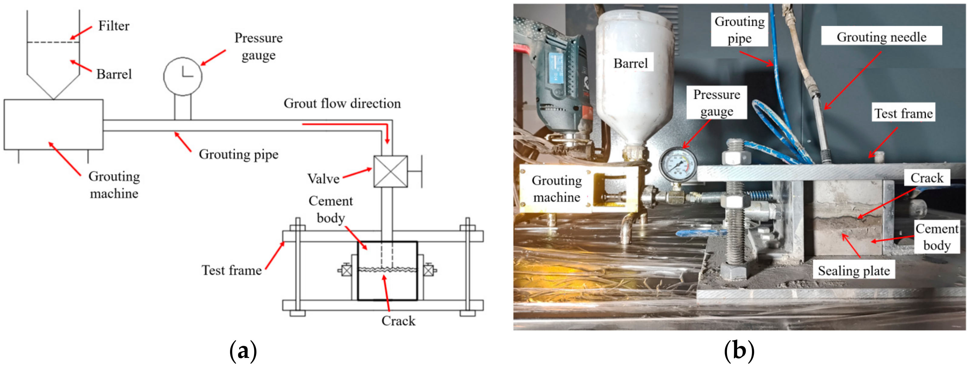
2.1.1. Grouting Simulation Test System
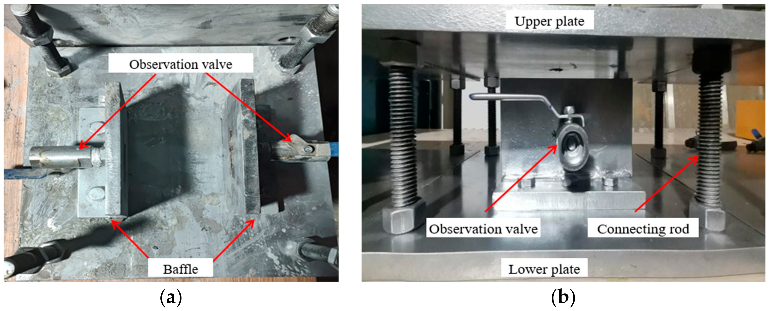
2.1.2. Impermeability Test System
2.2. Materials and Concrete Crack Sample
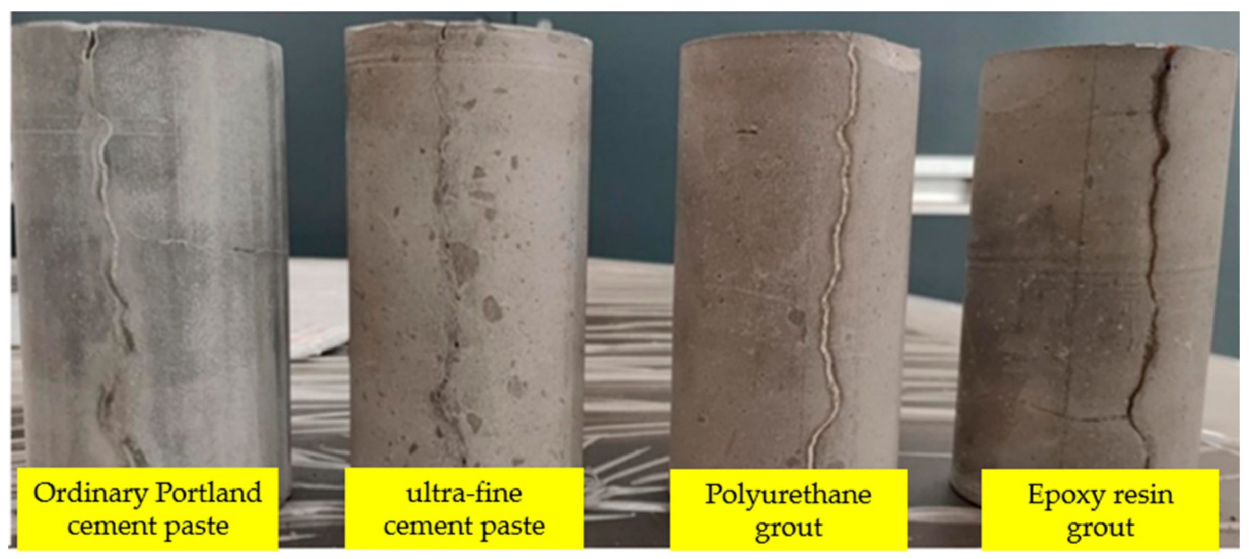
2.2.1. Grouting Material
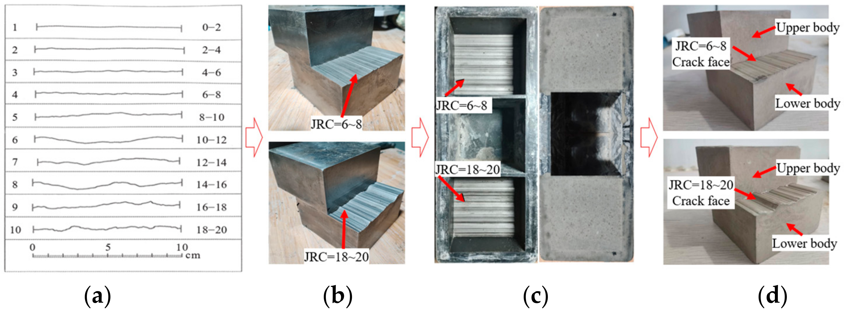
2.2.2. Grouted Concrete Crack Sample
2.3. Experimental Scheme
3. Results and Discussion
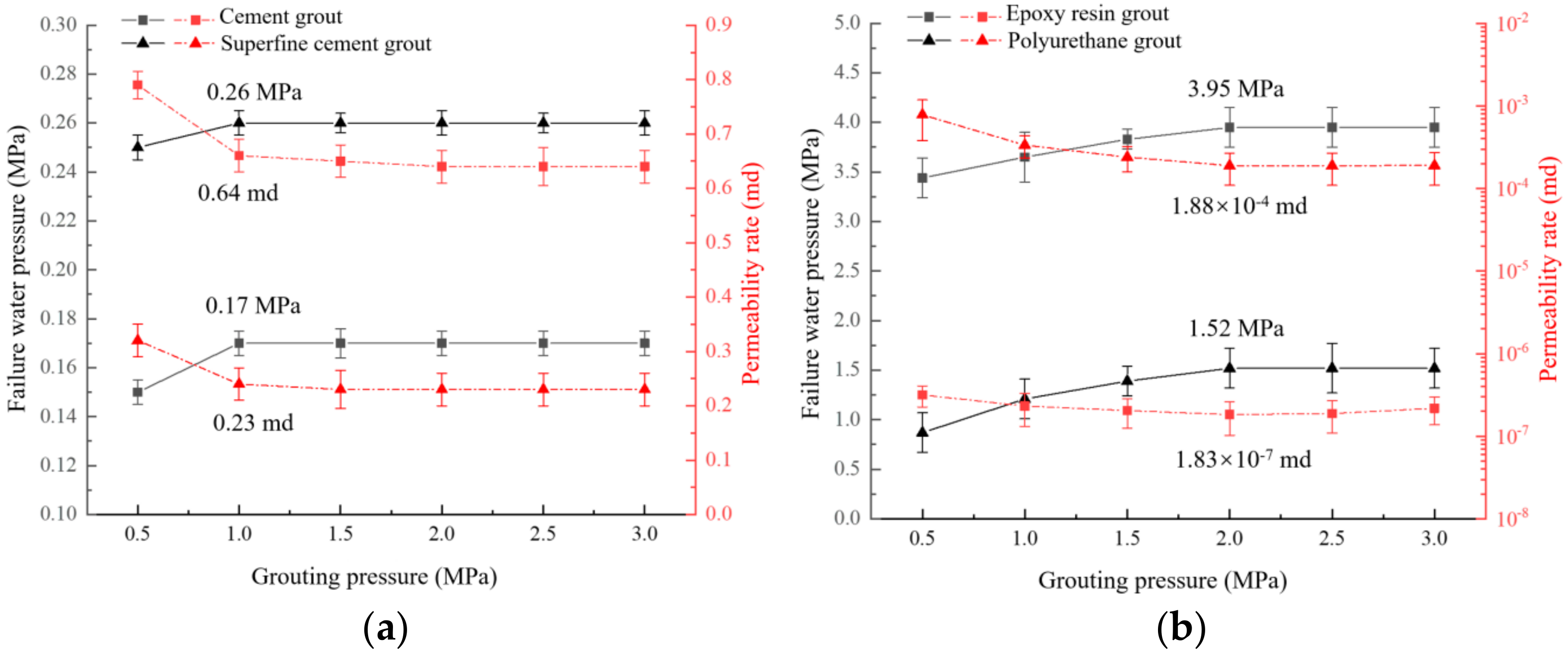
3.1. Influence of Grouting Pressure on Plugging Capacity
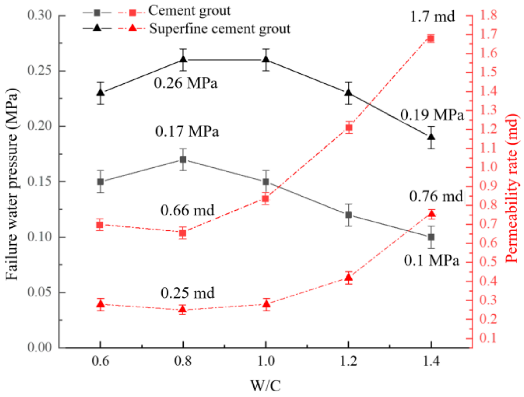
3.2. Influence of W/C on Plugging Capacity
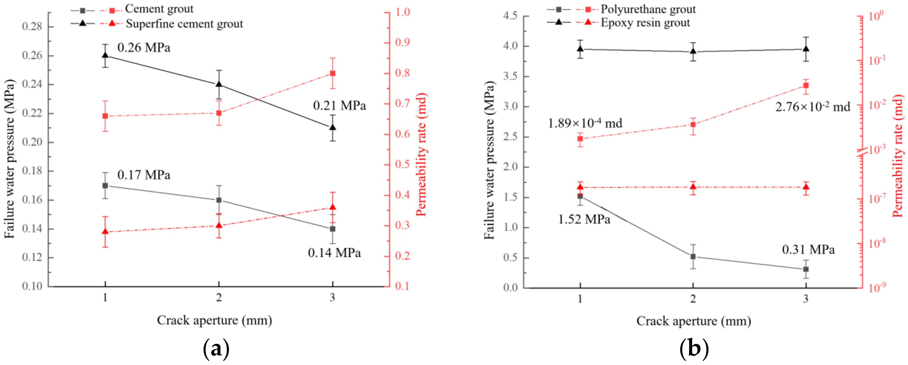
3.3. Influence of Crack Aperture on Plugging Capacity
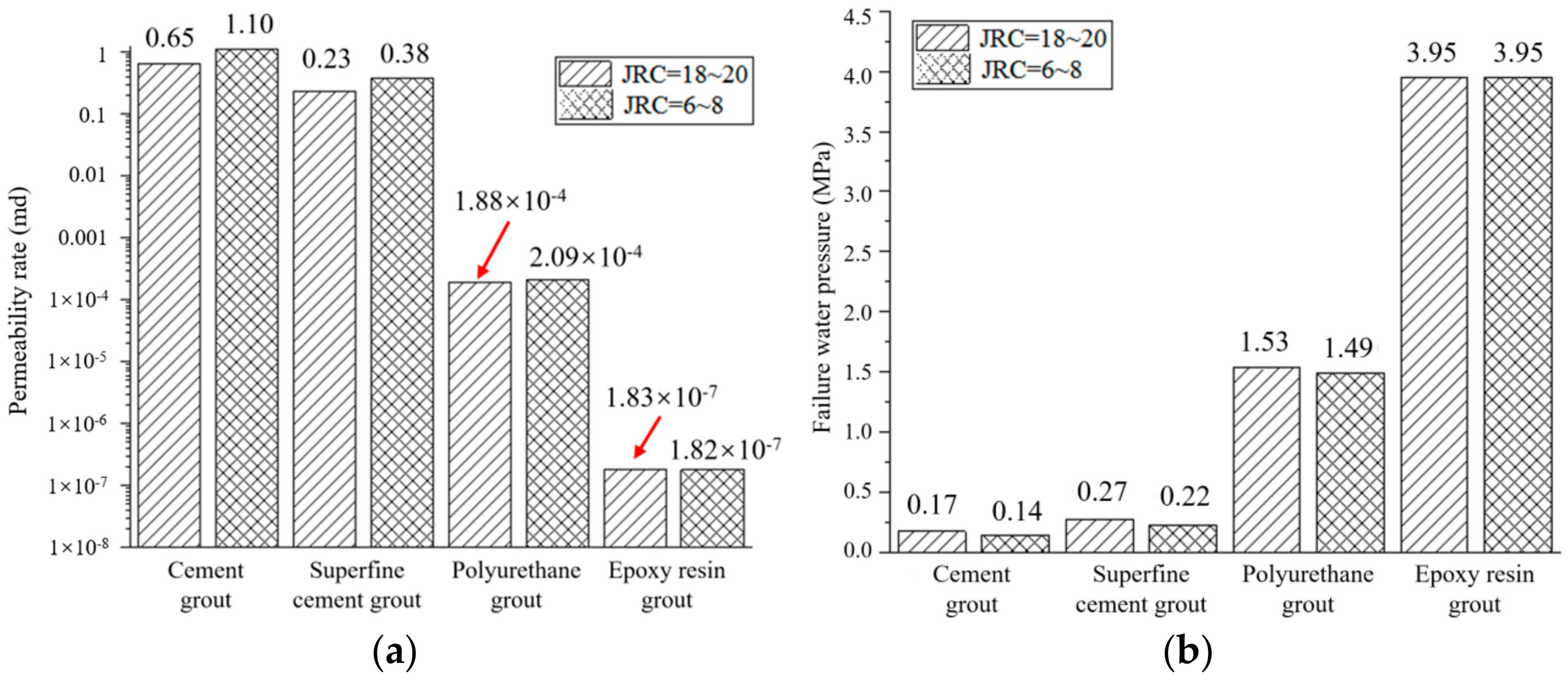
3.4. Influence of Crack Roughness on Plugging Capacity
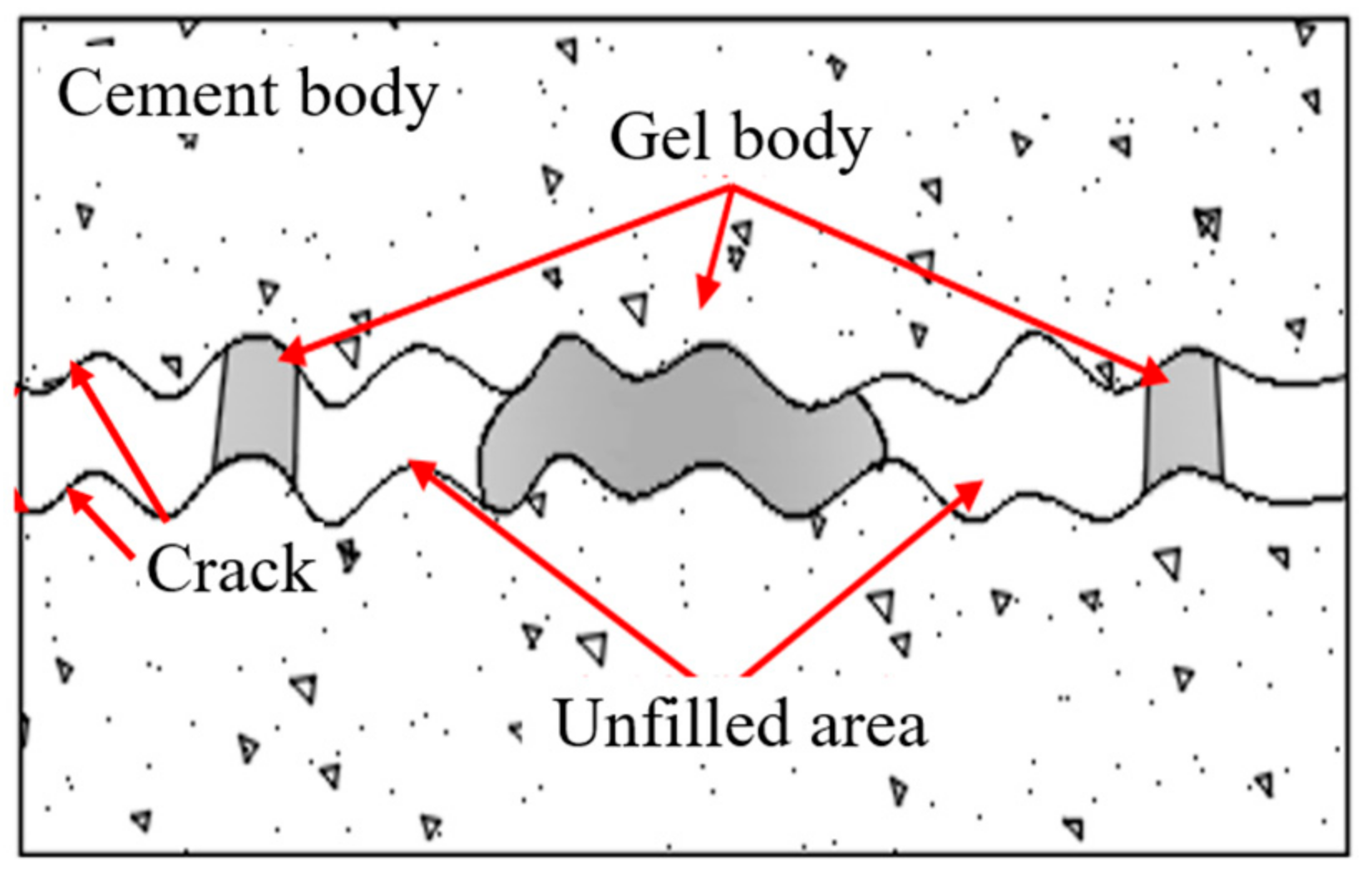
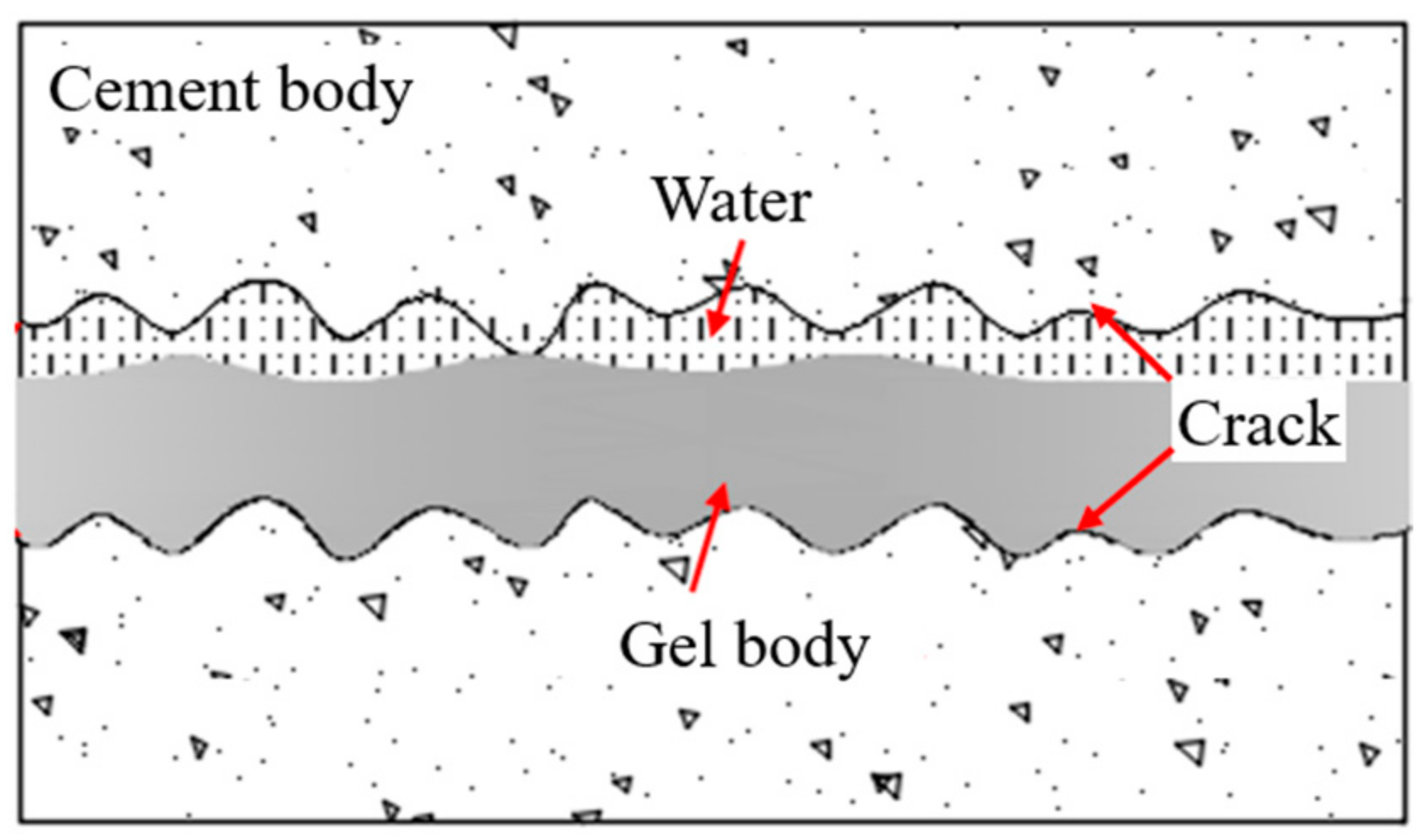
3.5. Microstructure Property of Grouted Concrete Crack
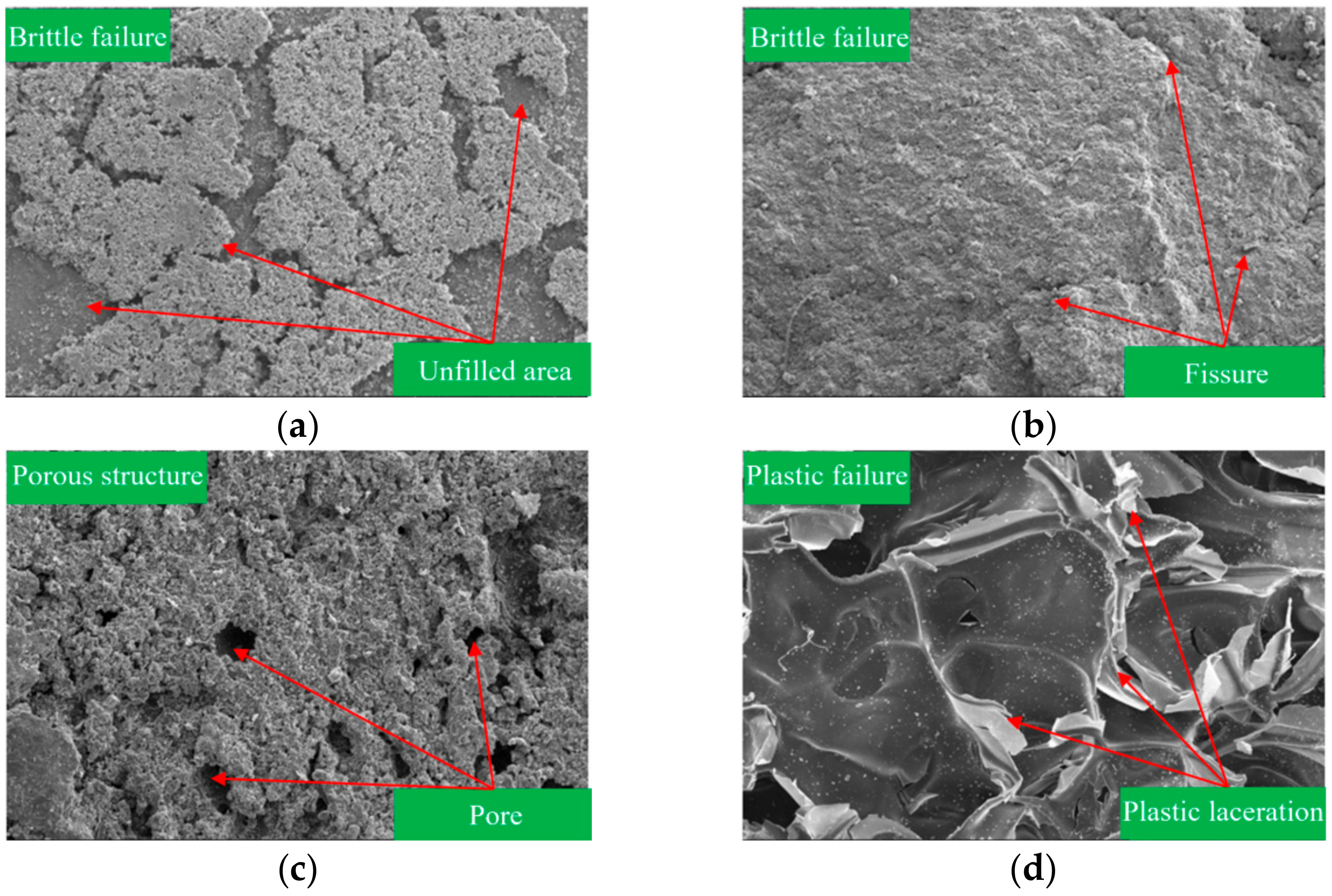
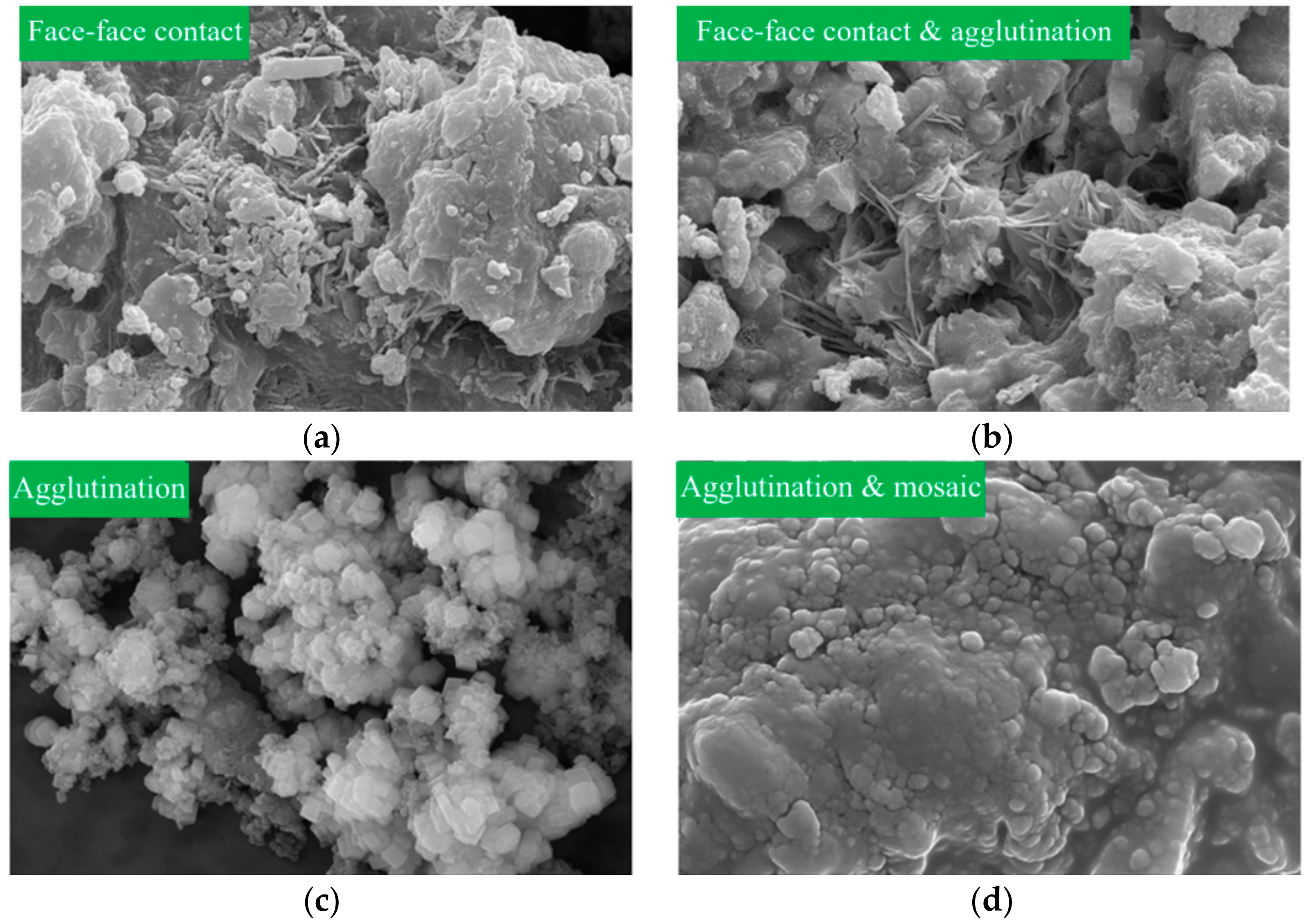
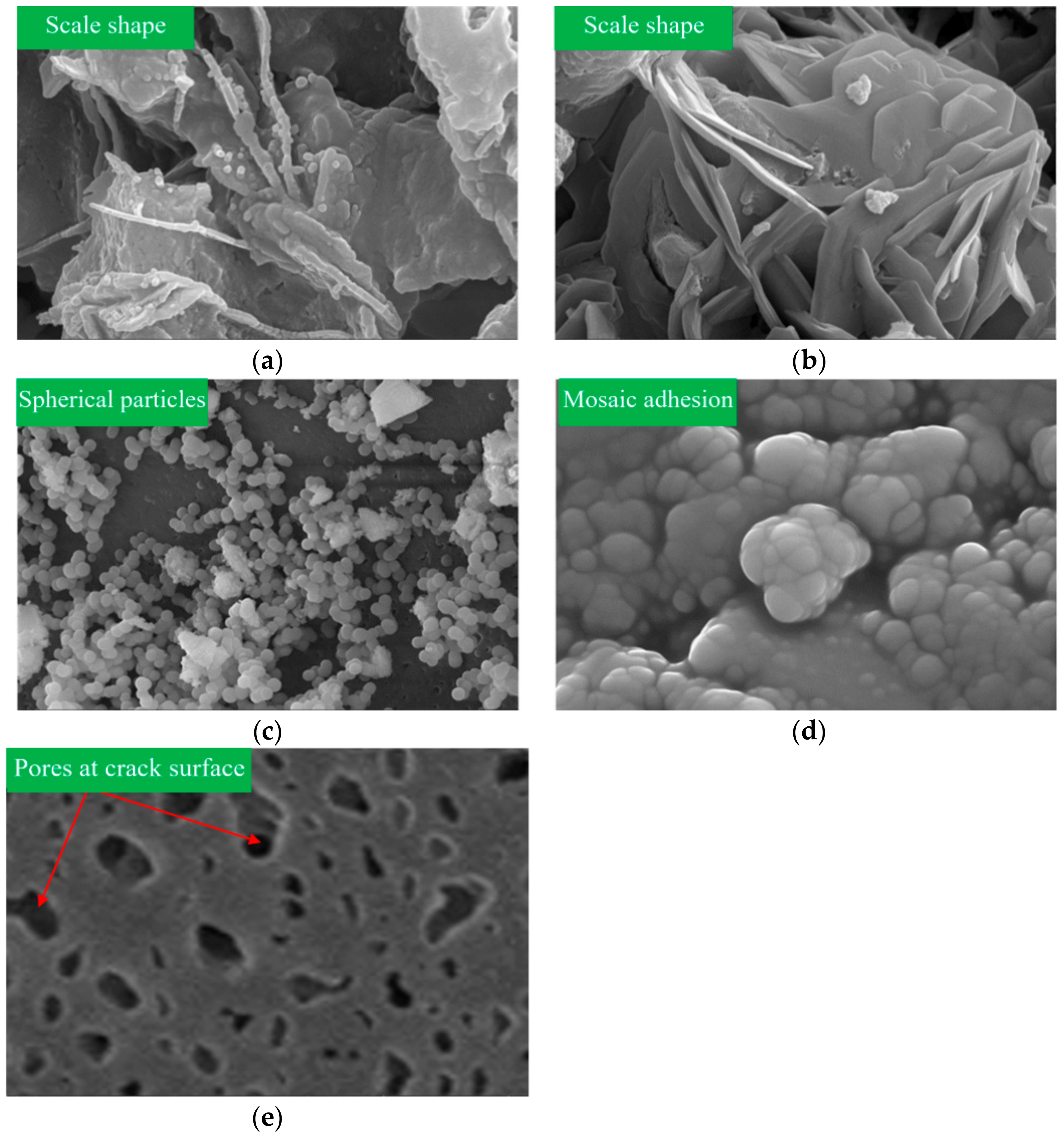
3.5.1. SEM Analysis
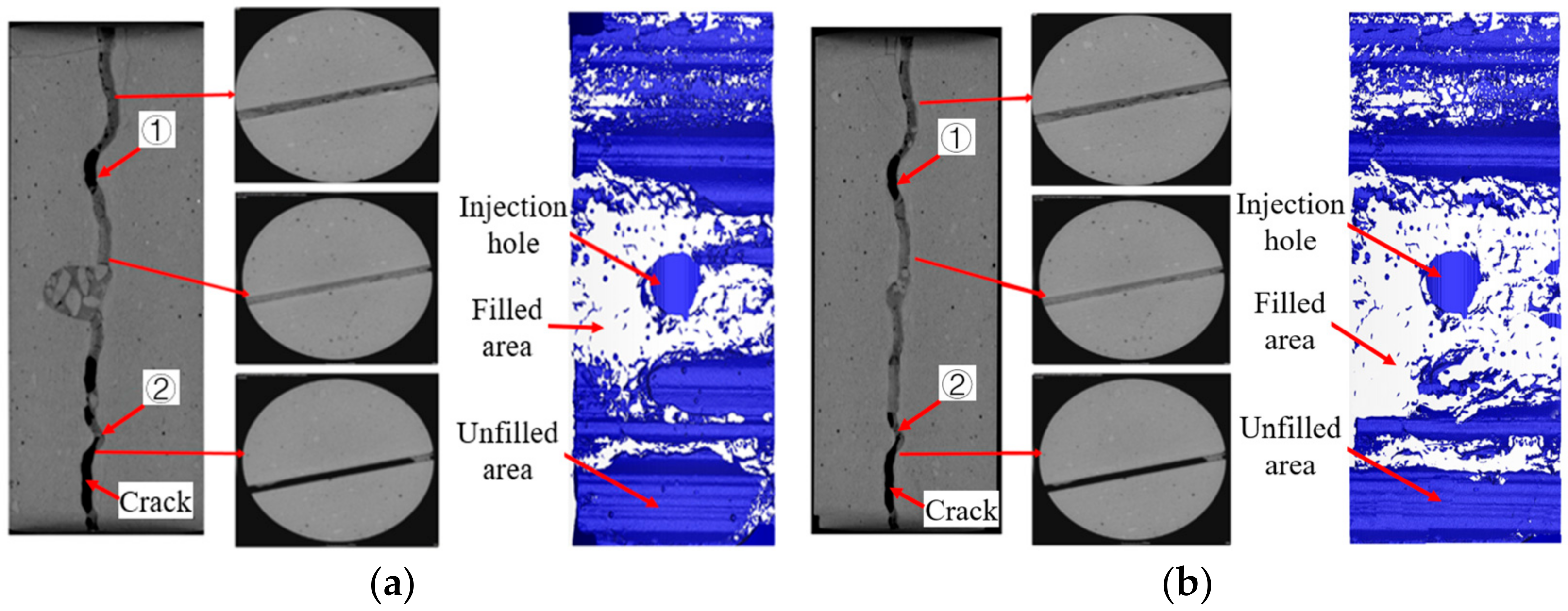
3.5.2. CT Analysis
4. Conclusions
- The concrete cracks grouted with epoxy resin had the highest seepage failure pressure and the lowest permeability, so their performance was the best. The applicability of the four grouting materials was ranked as follows: epoxy resin > polyurethane > ultrafine cement > ordinary Portland cement.
- When the grouting pressure does not exceed a certain value, the water-plugging performance of grouted concrete cracks is positively correlated with the grouting pressure. Otherwise, the increase in grouting pressure had no significant impact on the water-plugging performance of grouted concrete cracks. For ordinary Portland cement and ultrafine cement paste, this pressure value was 1 MPa. For polyurethane and epoxy resin grout, this pressure value was 2 MPa.
- There is an optimal water–cement ratio that makes the cement-based grout have the best water-plugging performance. The optimal water–cement ratios of ordinary Portland cement and ultrafine cement are both around 0.8. When the water–cement ratio of the grout was lower than 0.8, the fluidity of the grout was poor, which caused a low degree of crack filling. When the water–cement ratio of the grout was higher than 0.8, the grout had a bleeding phenomenon, which resulted in the seepage channel between the grout gel and crack side wall.
- The water-plugging performance of ordinary Portland cement, ultrafine cement, and polyurethane had a negative correlation with the crack aperture and a positive correlation with the crack roughness. The increase in crack aperture was conducive to generating new seepage channels, causing the poor water-plugging performance of grouted concrete cracks. The water-plugging performance of epoxy resin grout was not sensitive to crack aperture or roughness.
- From the perspective of microstructure, the filling degree of cement-based grout was low compared with chemical-based grout, such as polyurethane and epoxy resin grout. In addition, the filling degree of cement-based grout was affected by grout bleeding, shrinkage, and particle size. Polyurethane grout had many internal pores and was prone to brittle failure, resulting in interconnected pores. Epoxy resin grout has strong structural integrity and good compatibility with the concrete interface, which results in the water-plugging performance of polyurethane grout being lower than that of epoxy resin grout.
Author Contributions
Funding
Institutional Review Board Statement
Informed Consent Statement
Data Availability Statement
Conflicts of Interest
References
- Asakura, T.; Kojima, Y. Tunnel Maintenance in Japan. Tunn. Undergr. Sp. Technol. 2003, 18, 161–169. [Google Scholar] [CrossRef]
- Bagnoli, P.; Bonfanti, M.; Della Vecchia, G.; Lualdi, M.; Sgambi, L. A Method to Estimate Concrete Hydraulic Conductivity of Underground Tunnel to Assess Lining Degradation. Tunn. Undergr. Sp. Technol. 2015, 50, 415–423. [Google Scholar] [CrossRef]
- Cividini, A.; Contini, A.; Locatelli, L.; Gioda, G. Investigation on the Cause of Damages of a Deep Tunnel. Int. J. Geomech. 2012, 12, 722–731. [Google Scholar] [CrossRef]
- Shalabi, F.I.; Cording, E.J.; Paul, S.L. Concrete Segment Tunnel Lining Sealant Performance under Earthquake Loading. Tunn. Undergr. Sp. Technol. 2012, 31, 51–60. [Google Scholar] [CrossRef]
- Ghorbani, S.; Bour, K.; Javdan, R.; Bour, M. Design of Effective Grouting Pattern in Kerman Water Conveyance Tunnel Using DFN-DEM and Analytical Approaches. Int. J. Geosynth. Ground Eng. 2023, 9, 19. [Google Scholar] [CrossRef]
- Hoien, A.H.; Nilsen, B. Rock Mass Grouting in the Loren Tunnel: Case Study with the Main Focus on the Groutability and Feasibility of Drill Parameter Interpretation. Rock. Mech. Rock. Eng. 2014, 47, 967–983. [Google Scholar] [CrossRef]
- Andjelkovic, V.; Lazarevic, Z.; Nedovic, V.; Stojanovic, Z. Application of the Pressure Grouting in the Hydraulic Tunnels. Tunn. Undergr. Sp. Technol. 2013, 37, 165–179. [Google Scholar] [CrossRef]
- Panthi, K.K.; Nilsen, B. Uncertainty Analysis for Assessing Leakage Through Water Tunnels: A Case from Nepal Himalaya. Rock. Mech. Rock. Eng. 2010, 43, 629–639. [Google Scholar] [CrossRef]
- Türkmen, S.; Özgüzel, N. Grouting a Tunnel Cave-in from the Surface: A Case Study on Kurtkulağı Irrigation Tunnel, Turkey. Tunn. Undergr. Sp. Technol. 2003, 18, 365–375. [Google Scholar] [CrossRef]
- Briffaut, M.; Benboudjema, F.; D’Aloia, L. Effect of fibres on early age cracking of concrete tunnel lining. Part II: Numerical simulations. Tunn. Undergr. Sp. Technol. 2016, 59, 221–229. [Google Scholar] [CrossRef]
- Funehag, J.; Thörn, J. Radial penetration of cementitious grout—Laboratory verification of grout spread in a fracture model. Tunn. Undergr. Sp. Technol. 2018, 72, 228–232. [Google Scholar] [CrossRef]
- Draganovic, A. Bleeding and Filtration of Cement-Based Grout; KTH Royal Institute of Technology: Stockholm, Sweden, 2009. [Google Scholar]
- Draganovic, A.; Stille, H. Cement-based grouts measured. Tunn. Undergr. Sp. Technol. 2014, 43, 101–112. [Google Scholar] [CrossRef]
- Lu, Y.; He, M.; Wang, L. Experiments on the microscopic process of particle filtration of cement grouts within a rock frac-ture. Tunn. Undergr. Sp. Technol. 2020, 95, 103157. [Google Scholar] [CrossRef]
- Wang, X.; Xiao, F.; Zhang, Q.; Zhou, A.; Liu, R. Grouting characteristics in rock fractures with rough surfaces: Apparatus design and experimental study. Measurement 2021, 184, 109870. [Google Scholar] [CrossRef]
- Li, S.; Liu, R.; Zhang, Q.; Zhang, X. Protection against water or mud inrush in tunnels by grouting: A review. J. Rock. Mech. Geotechnol. 2016, 8, 753–766. [Google Scholar] [CrossRef]
- Zhu, G.; Zhang, Q.; Lin, X.; Liu, R.; Zhang, L.; Zhang, J. Analysis of the Sealing Mechanism of Cement-Sodium Silicate Grout in Rock Fractures with Flowing Water. Water 2020, 12, 1935. [Google Scholar] [CrossRef]
- Sui, W.; Liu, J.; Hu, W.; Qi, J.; Zhan, K. Experimental investigation on sealing efficiency of chemical grouting in rock frac-ture with flowing water. Tunn. Undergr. Sp. Technol. 2015, 50, 239–249. [Google Scholar] [CrossRef]
- Ping, Y.; Li, T.; Li, S. Effect of different factors on propagation of carbon fiber composite cement grout in a fracture with flow-ing water. Constr. Build. Mater. 2016, 121, 501–506. [Google Scholar]
- Yang, P.; Liu, Y.; Gao, S. Experimental investigation on the diffusion of carbon fibre composite grouts in rough fractures with flowing water. Tunn. Undergr. Sp. Technol. 2020, 95, 103146. [Google Scholar] [CrossRef]
- Liu, Y.; Yang, P.; Ku, T. Effect of different nanoparticles on the grouting performance of cement-based grouts in dynamic water condition. Constr. Build. Mater. 2020, 248, 118663. [Google Scholar] [CrossRef]
- ASTM C942-15; Standard Test Method for Compressive Strength of Grouts for Preplaced-Aggregate Concrete in the Laboratory. ASTM: West Conshohocken, PA, USA, 2021.
- ASTM C78-09; Standard Test Method for Flexural Strength of Concrete. ASTM: West Conshohocken, PA, USA, 2010.
- Barton, N.; Choubey, V. The shear strength of rock joints in theory and practice. Rock. Mech. Rock. Eng. 1978, 10, 1–54. [Google Scholar] [CrossRef]
- Bin, Z.; Yuanfu, Z.; Xuefu, Z. Experimental Study on Grouting Diffusion Law of the Different Crack Widths in Tunnel Lining. Ksce. J. Civ. Eng. 2023, 27, 4. [Google Scholar]
- Rahman, M.d.M.; Akhtarul Islam, M. Application of Epoxy Resins in Building Materials: Progress and Prospects. Polym. Bull. 2022, 79, 1949–1975. [Google Scholar] [CrossRef]
- Abreu, L.M.P.D.; Carvalho, H.; Fakury, R.H.; Rodrigues, F.C.; Caldas, R.B. Experimental Evaluation of Column Base Connections Composed by Different Grout Types Subject to Shear. Eng. Fail. Anal. 2021, 120, 105090. [Google Scholar] [CrossRef]
- Shamsuddoha, M.; Islam, M.M.; Aravinthan, T.; Manalo, A.; Lau, K. Characterisation of Mechanical and Thermal Properties of Epoxy Grouts for Composite Repair of Steel Pipelines. Mater. Design. 2013, 52, 315–327. [Google Scholar] [CrossRef]


| Material Type | Initial Setting Time (min) | Final Setting Time (min) | Compressive Strength (MPa) | Flexural Strength (MPa) | ||
|---|---|---|---|---|---|---|
| 3d | 28d | 3d | 28d | |||
| Portland cement | 131 | 217 | 17 | 45.2 | 3.5 | 6.5 |
| Ultrafine cement | 152 | 423 | 5 | 30 | 60 | 5 |
| Material Type | Initial Setting Time (min) | Final Setting Time (min) | Compressive Strength (MPa) | Viscosity (mPa·s) |
|---|---|---|---|---|
| Polyurethane grout | Immediate reaction to water | 144 | 0.2 | 800~1000 |
| Epoxy resin grout | 60 | 1440 | 80 | 1000~1400 |
| Grout | W/C | Grouting Pressure (MPa) | Crack Aperture (mm) | Crack Roughness: JRC |
|---|---|---|---|---|
| Ordinary Portland/ultrafine cement paste | 0.8 | 0.5, 1.0, 1.5, 2.0, 2.5, 3.0 | 1 | 18~20 |
| 0.6, 0.8, 1.0, 1.2, 1.4 | 1.0 | 1 | 18~20 | |
| 0.8 | 1.0 | 1, 2, 3 | 18~20 | |
| 0.8 | 1.0 | 1 | 6~8, 18~20 | |
| Polyurethane grout | — | 0.5, 1.0, 1.5, 2.0, 2.5, 3.0 | 1 | 18~20 |
| — | 2.0 | 1, 2, 3 | 18~20 | |
| — | 2.0 | 1 | 6~8, 18~20 | |
| Epoxy resin grout | — | 0.5, 1.0, 1.5, 2.0, 2.5, 3.0 | 1 | 18~20 |
| — | 2.0 | 1, 2, 3 | 18~20 | |
| — | 2.0 | 1 | 6~8, 18~20 |
Disclaimer/Publisher’s Note: The statements, opinions and data contained in all publications are solely those of the individual author(s) and contributor(s) and not of MDPI and/or the editor(s). MDPI and/or the editor(s) disclaim responsibility for any injury to people or property resulting from any ideas, methods, instructions or products referred to in the content. |
© 2024 by the authors. Licensee MDPI, Basel, Switzerland. This article is an open access article distributed under the terms and conditions of the Creative Commons Attribution (CC BY) license (https://creativecommons.org/licenses/by/4.0/).
Share and Cite
Zhang, L.; Huang, C.; Li, Z.; Wang, A.; Gao, M.; Gao, Y.; Wang, X. Experimental Study on Water-Plugging Performance of Grouted Concrete Crack. Materials 2024, 17, 1568. https://doi.org/10.3390/ma17071568
Zhang L, Huang C, Li Z, Wang A, Gao M, Gao Y, Wang X. Experimental Study on Water-Plugging Performance of Grouted Concrete Crack. Materials. 2024; 17(7):1568. https://doi.org/10.3390/ma17071568
Chicago/Turabian StyleZhang, Lianzhen, Changxin Huang, Zhipeng Li, Anni Wang, Meng Gao, Yang Gao, and Xiaochen Wang. 2024. "Experimental Study on Water-Plugging Performance of Grouted Concrete Crack" Materials 17, no. 7: 1568. https://doi.org/10.3390/ma17071568