1. Introduction
Phase change materials (PCMs) offer an effective way of storing and releasing heat as the temperature during phase transition remains almost constant. PCMs make use of the phase transition enthalpy occurring upon melting and solidification. As an energy-efficient thermal management tool, PCMs are used in a wide range of applications such as temperature control in buildings and photovoltaic systems as well as for thermo-regulation in textiles [
1,
2,
3,
4]. However, the direct use of PCMs for latent heat storage systems is often hindered due to their low thermal conductivity. The thermal conductivity of organic PCMs is found to be in the range between 0.1 W/(m·K) and 0.4 W/(m·K), while inorganic PCMs exhibit values between 0.5 W/(m·K) and 1.3 W/(m·K) [
1]. Numerous studies address this topic by proposing the combination of PCMs with highly conductive materials. To enhance the effective thermal conductivity of a latent heat storage system, carbon nanofiber, carbon nanotubes, and silver nanoparticles can be used [
5,
6]. Another approach is the infiltration of PCMs into open-cell or closed-cell aluminum foams [
7,
8]. While the composite structures of metallic foam and PCMs that are investigated in the literature demonstrate convenient thermal performance, there are drawbacks due to the limitations of the foam fabrication. For example, the foam porosity as a main composite parameter cannot be freely adjusted. Another drawback is the random distribution of pores within the foam structure.
As an alternative to foam structures, additively manufactured micro-lattice structures can be used. The main advantage of additively manufactured micro-lattice structures is the high fabrication flexibility and local adaptivity of the lattice density. With respect to micro-lattice–PCM composites, the increased geometric flexibility leads to an easier optimization process of the relation between matrix density and heat storage volume. Takarazawa et al. investigated the heat-transfer and pressure-drop characteristics of micro-lattices [
9]. Different lattice block designs were compared. It could be shown that the face-centered cubic (FCC) lattices exhibit superior effective thermal conductivity compared to the body-centered cubic (BCC) lattices. Bracconi et al. analyzed the effective thermal conductivity of isotropic and anisotropic lattice structures by means of finite element (FE) models [
10]. The authors stated that the effective thermal conductivity is not affected by varying unit cell size and hence mainly depends on the porosity and the thermal conductivity of the solid. Experimental investigations on heat sinks fabricated using laser powder bed fusion (LPBF) were presented by Wong et al. [
11]. Different heat sink designs, including one lattice structure, were fabricated and experimentally compared regarding their heat-transfer and pressure-drop characteristics. The convective heat dissipation on the lattice structure was found to be inferior compared to the other heat sinks.
While the stated studies demonstrate several influences of geometric parameters on the heat-transfer characteristics of additively manufactured lattice structures, additional examinations are required to fully comprehend the effects of LPBF on the effective thermal conductivity of the lattices for different strut diameters and unit cell sizes. In particular, the thermal performance of lattice structures filled with PCMs has not yet been addressed in the literature and thus needs to be examined. Therefore, this paper deals with the LPBF fabrication and thermal characterization of regular lattice structures of different geometric parameters. The transient plane source (TPS) method was used to obtain the effective thermal conductivity of the manufactured specimens. The measurements were conducted for air-filled and PCM-filled lattices. The measurements were accompanied by FE simulations to interpret the experimental results and detect possible uncertainty effects. The investigations addressed the following aspects:
Influence of LPBF process parameters on the resulting lattice geometry;
Comparative TPS measurements of thermal conductivity of air-filled and PCM-filled lattice structures;
Estimation of heat-transfer characteristics of manufactured lattice structures using analytical and numerical calculations.
2. Materials and Methods
In the following paragraphs, the design and fabrication of selected lattice structures are described. The experimental set-up and test procedure for obtaining the thermal conductivity are illustrated. Furthermore, the thermal FE model of the lattice structures is presented.
2.1. Lattice Structure Design and Manufacturing
Regular lattice structures with BCC unit cells were chosen for the experimental and numerical investigations. By using BCC unit cells, good comparability with other studies on additively manufactured metallic lattice structures is achieved, as BCC unit cells are often considered [
12,
13,
14,
15]. In a BCC lattice structure, all struts exhibit the same inclination angle to the base plate during manufacturing (approx. 35°), which leads to a homogeneous strut thickness [
13]. Furthermore, the relative density can be changed over a particularly wide range using this unit cell type [
16,
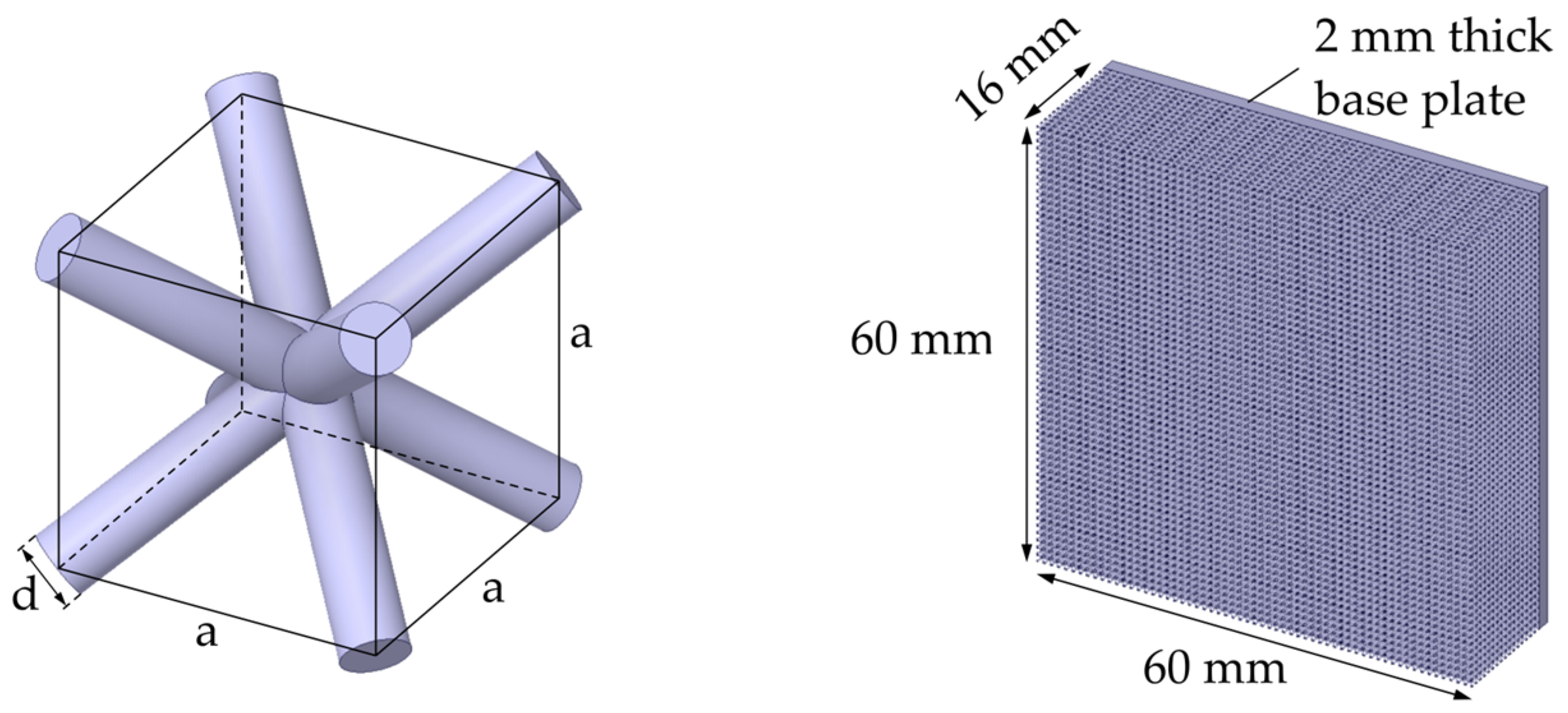
17]. Based on the BCC unit cell, lattice structures with a bounding box of 60 mm × 60 mm × 16 mm were considered. In addition to the lattice structure, the specimen geometry consisted of a base plate with a thickness of 2 mm and a cross section of 60 mm × 60 mm. The unit cell and the complete specimen geometry are shown in
Figure 1.
The relative density
of a BCC lattice is defined by the ratio of the strut diameter to the cell size
and can be calculated using the polynomial approximation given by Zhang et al. [
18]
where
is the lattice volume and
the enclosing cuboid volume.
The specimens were additively manufactured through LPBF using the alloy AlSi10Mg, according to ASTM F3318 [
19], by the manufacturer Concept Laser (Lichtenfels, Germany), with the following particle size distribution: Q3, 10% = 19.3 µm; Q3, 50% = 28.8 µm; and Q3, 90% = 46.9 µm (measured using the particle analyzer Camsizer X2, Retsch Technology, Haan, Germany). The as-built specification of heat conductivity was 125 W/(m·K). This value was determined as the average of three measurements using the TPS method. The LPBF machine used was a Lasertec12 by DMG Mori/Realizer (Bielefeld, Germany) from 2020. The machine specifications are shown in
Table 1.
The purpose of the investigations was to find dependencies between the effective thermal conductivity and the cell size
of the unit cells as well as the strut diameter
. Therefore, the size of the unit cells and the laser parametrization during manufacturing were varied using a D-optimal experimental design, resulting in different strut diameters. The parameters were chosen in such a manner to cover a wide range of
.
Table 2 lists the fabricated specimens and the corresponding geometry parameters. The corresponding laser parameters used for obtaining the different lattice structures are shown in
Table 3. The selection of the laser parameters was based on the results of comprehensive preliminary manufacturing experiments that are not within the focus of the present study.
Two specimens of each geometric configuration were considered as required by the experimental method for obtaining the effective thermal conductivity. The strut diameter for each specimen was estimated by adjusting the corresponding parameter within the CAD model until the measured effective density coincided with the virtual effective density. This estimation assumed an ideal lattice topology with constant strut diameter. The obtained strut diameter values were validated through a microscopic examination of the specimens. Furthermore, the estimation of the relative density by means of Equation (1) was found to be in good agreement with the relative density obtained by weighing the specimens.
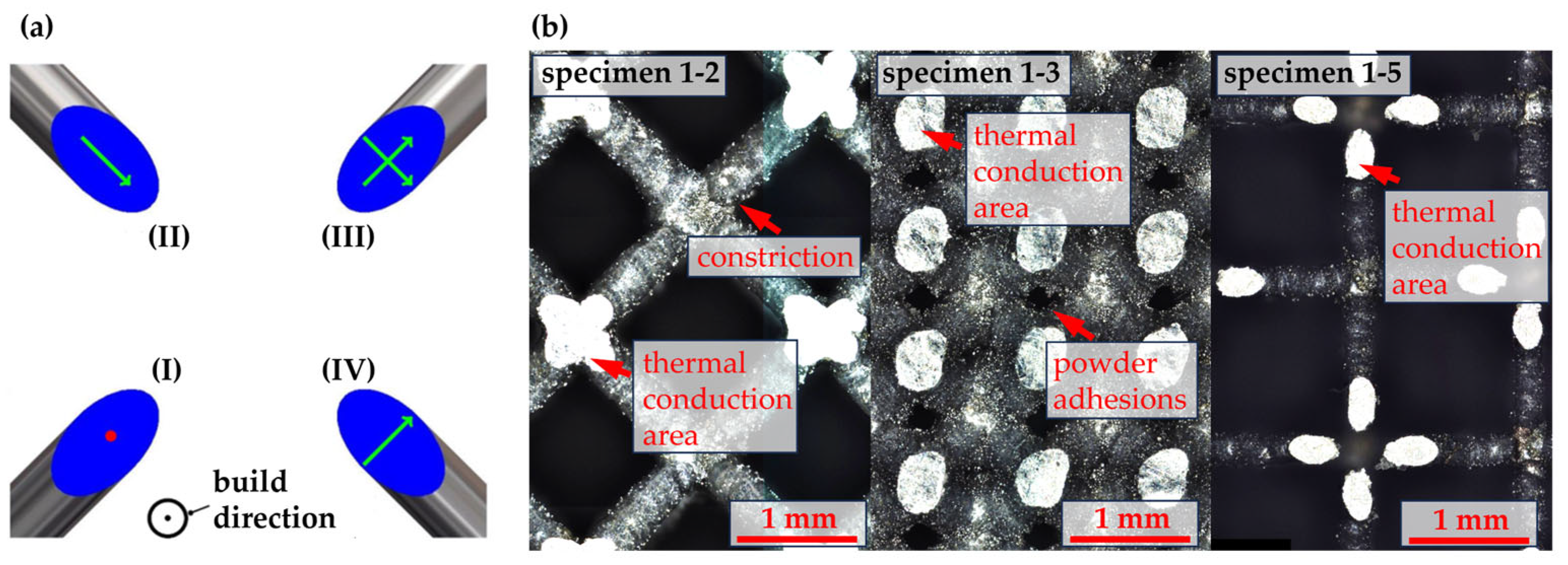
As a special scanning strategy, the quasi-point scanning strategy was used for the manufacturing of the lattice section of the specimens [
20]. Instead of scanning a contour along the cross section of the struts and filling it using hatches, the cross sections were exposed using two crossed scanning vectors (cross, see
Figure 2a). This very defined energy input leads to very thin and even struts in the lattice structure [
21].
Figure 2 depicts the different scanning strategies as well as a detailed view on the resulting struts in the manufactured specimens. The even areas on the outer specimen surfaces can easily be seen due to the high reflectivity (see
Figure 2b). The lattice geometry is varied in a wide range depending on the geometric parametrization. The resulting struts are even and free of major defects. However, depending on the manufacturing parametrization, the struts can exhibit minor defects, like constrictions at the junction between struts and nodes or powder adhesions on the struts.
2.2. Infiltration with Phase Change Material
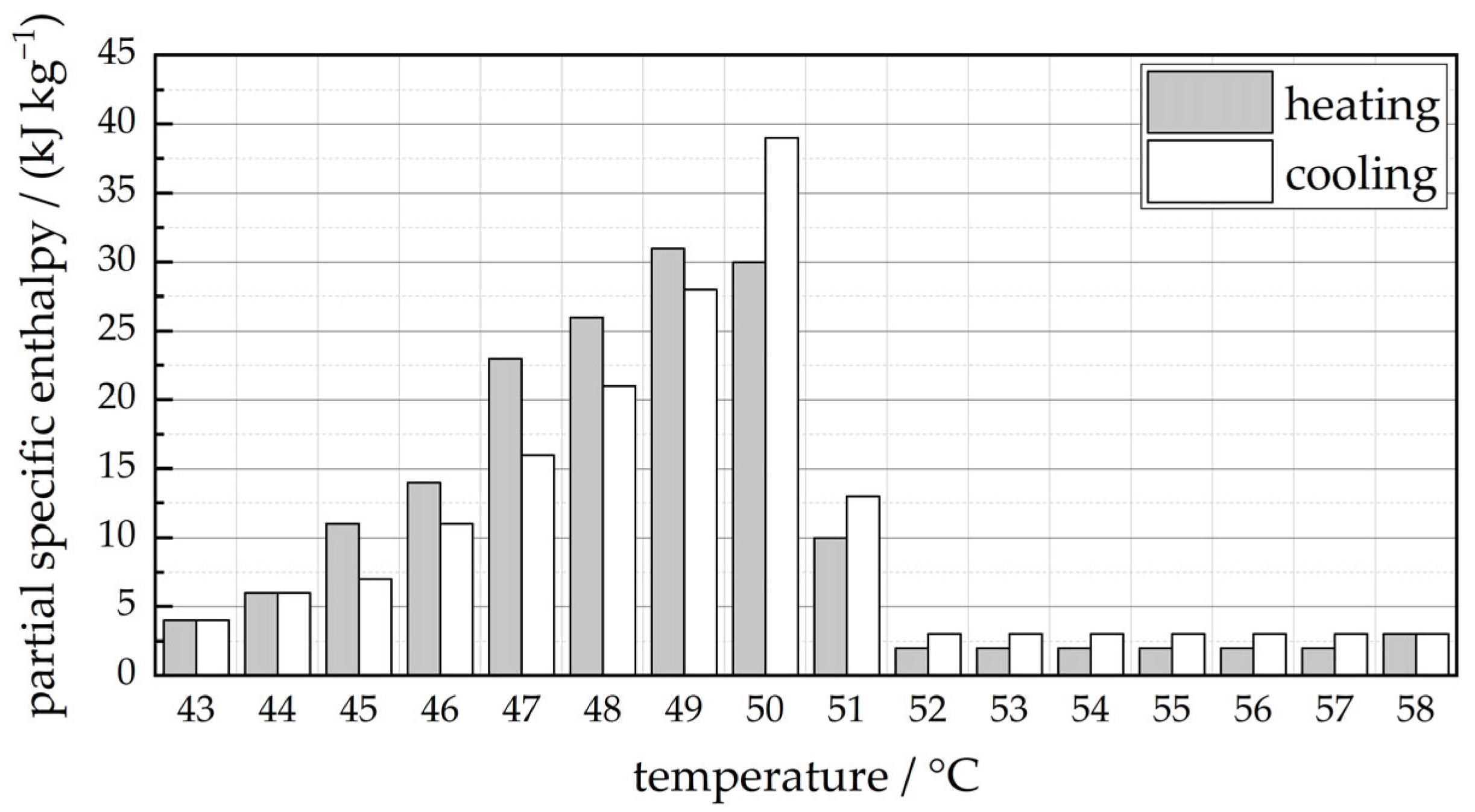
Typical PCMs can be categorized into organic and inorganic PCMs. Since inorganic PCMs such as salt hydrates and fatty acids are mostly not compatible with metals and exhibit non-congruent melting, an organic, paraffin-based PCM was used for the investigations. The PCM RT50 of the manufacturer Rubitherm Technologies (Berlin, Germany) was selected. RT50 exhibits a solid–liquid phase change temperature range between approximately 45 °C and 51 °C. The thermal conductivity of RT50 amounts to 0.2 W/(m·K), as stated by the manufacturer [
22]. The temperature-dependent partial specific enthalpy values within the solid–liquid phase change are shown in
Figure 3. The specific enthalpy difference for the temperature range of 43 °C to 58 °C, as stated by the manufacturer, amounts to 160 J/g. In the work of other authors such as Losada-Pérez et al., that comprises calorimetric measurements on similar paraffin-based PCMs of the same manufacturer, comparable, but slightly lower values are reported (e.g., 138 J/g for RT42 in the range of 34 °C to 51 °C) [
23].
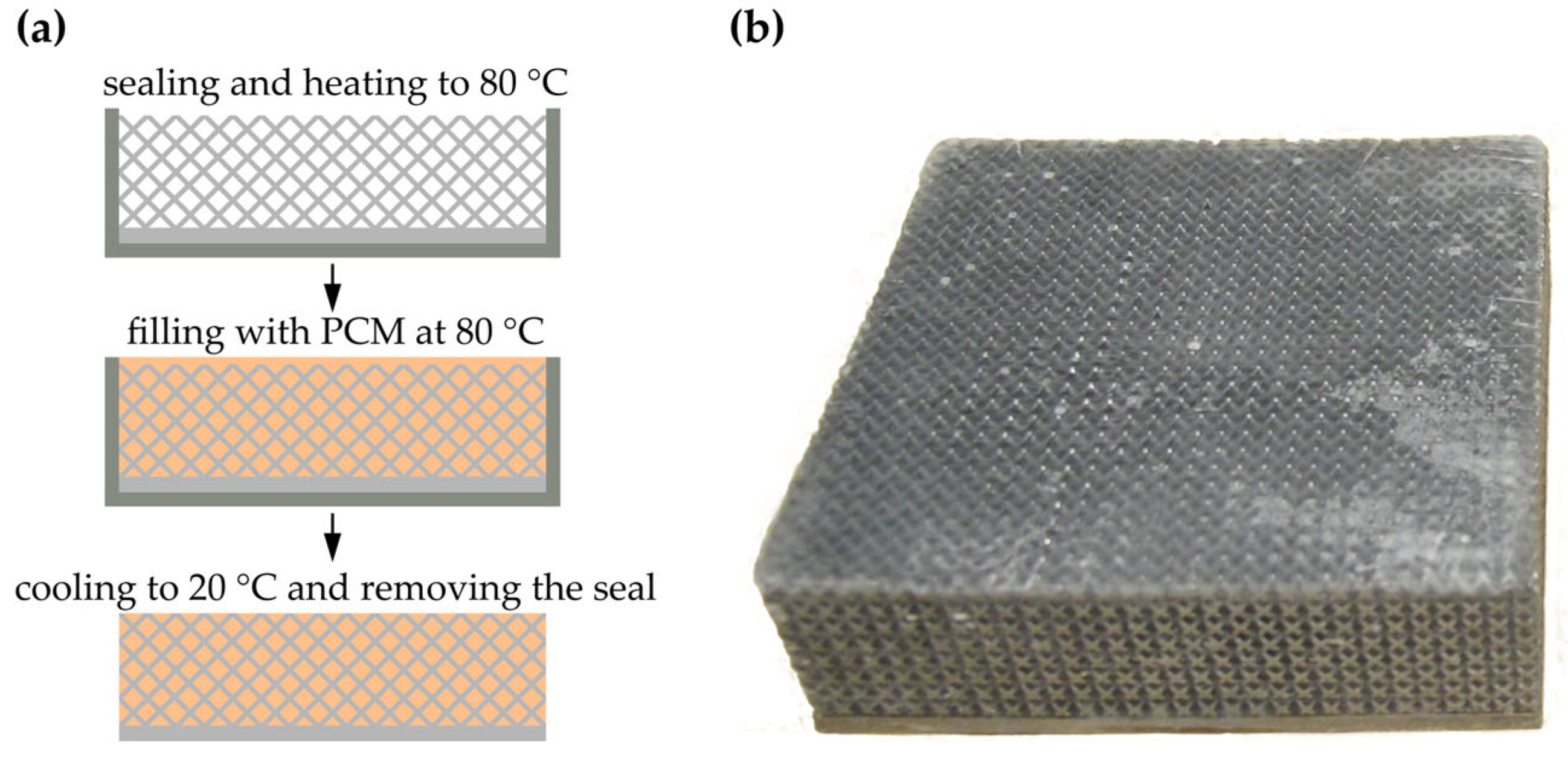
The infiltration process is illustrated in
Figure 4a. At first, the outer surfaces of the specimens were sealed using polyvinyl chloride (PVC) tape. To avoid a low infiltration ratio due to the premature solidification of the PCM upon contacting the lattice structure, the specimens were heated up to 80 °C using a convection oven. The PCM was molten at the same oven temperature. After a cooling period of over 15 h at an ambient temperature of 20 °C, the PVC tape was removed and the outer surfaces of the specimens were manually ground to remove PCM residuals outside of the defined specimen volume. An exemplary infiltrated specimen is shown in
Figure 4b.
The heat-storage characteristics of the specimens can be described by means of the enthalpy difference
with respect to a defined temperature range. To illustrate the influence of the relative lattice density on the storable heat within the air-filled lattices (
) and the PCM-filled lattices (
), the enthalpy difference is calculated for all specimens based on the specific heat capacity of aluminum (
J/(kg K)) and the specific enthalpy curve
of the PCM RT50 (see
Figure 3) using
The values are calculated considering an exemplary temperature rise from 43 °C to 58 °C, as listed in
Table 4. Within the considered temperature range, the infiltrated specimens 1–5 and 2–5 exhibit the highest heat storability due to the low lattice density and thus high PCM mass.
2.3. Heat-Transfer Investigation through TPS Method
The TPS method is described in DIN EN ISO 22007-2 [
24]. The purpose of the TPS method is the temperature-dependent determination of the thermal conductivity for various materials, ranging from insulating materials with very low thermal conductivity to materials with very high conductivity, such as copper. The further description of the TPS method is taken from the manual of the TPS instrument manufacturer Hot Disk
® (Göteborg, Sweden) [
25]. The measuring range of the TPS method is given as [0.005, 1800] W/(m·K). The TPS method was selected as it meets the requirements for measuring porous metallic structures such as good thermal contact and proper measurement area to cover a representative geometry or rather several pores. It has been proven as suitable in several investigations [
26,
27,
28].
In the TPS method, a sensor made of electrically conductive nickel wire, which is in the form of a double spiral and embedded in polyimide foil, is positioned between two identical samples. The 60–80 µm thick sensor acts as a heat source to raise the sample temperature and, at the same time, as a resistance thermometer.
For a successful determination of the thermal characteristic values, restrictions for input variables, like measuring time, heat power, and relaxation time, and characteristic result variables, like temperature gradients and the penetration depth of the heat wave, must be observed. First, the specimens were measured without surface treatment. Afterwards, the specimens were ground to generate plane-parallel, flat surfaces and measured again. The grinding was performed using sandpaper of grit size P220. By comparing the results of the measurements before and after the grinding process, conclusions were aimed to be drawn regarding the required surface treatment of the specimens. Before the measurements, the specimens were conditioned for at least 24 h at room temperature.
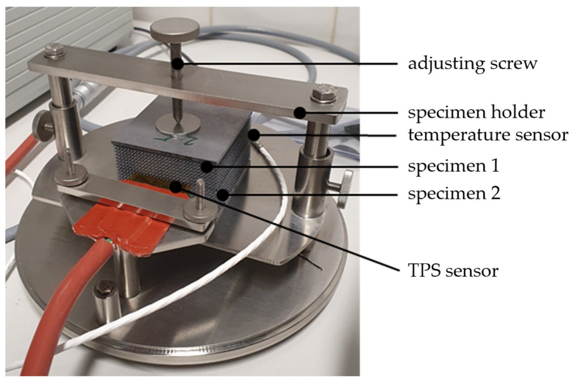
The tests on the aluminum specimens were carried out with the aid of a HotDisk TP2500S measuring device (Hot Disk AB, Göteborg, Sweden). The experimental setup is illustrated in
Figure 5. The sensor was positioned between two identical specimens. Slight pressure was applied to the samples and the sensor via a set screw to ensure good contact and thus heat conduction. The thin and flexible sensor allowed good thermal contact between the sensor and the sample. The use of a protective hood, not shown, reduced convective influences. The relaxation time in between measurements was at least 36 times the measurement duration.
The aluminum specimens were measured using the 3D bulk method. The cubic specimens were loaded with 0.15–4.5 W heating power within the measurement duration of 1–20 s; see
Table 5. The radius of the sensor used was 9.87 mm.
To determine the PCM influence on the thermal conductivity of aluminum specimens, the seven specimen pairs were measured before and after infiltration with the PCM. Each measurement was made using two identical specimens, one placed above and one below the sensor, and taking the average. The measurement for each specimen pair was performed at least three times after the appropriate relaxation time. The infiltrated PCM was expected to have a neglectable influence on the heat-transfer characteristics of the composite structure due to the low thermal conductivity of the PCM. While the thermal conductivity of PCM is higher compared to air, the lack of convective heat transfer inside infiltrated lattices might affect the measurements. Furthermore, it was to be investigated if the continuous surface of the aluminum–PCM composite provides measurements of enhanced accuracy compared to the sole lattice contact areas due the enhanced heat input into the specimens.
2.4. Finite Element Simulation
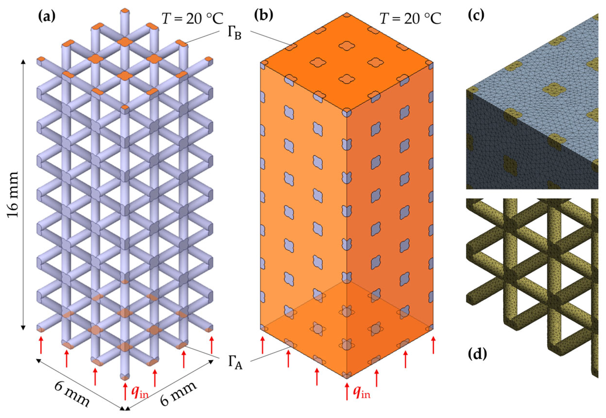
Steady-state FE simulations were conducted aiming to evaluate the experimental results with respect to possible measurement uncertainties. Two FE models were built to simulate the thermal behavior of the manufactured lattice structures. The first model represents the sole aluminum lattice structure. The second model comprises the lattice structure with infiltrated PCM. The differential equation to be solved is the steady-state Laplace equation without internal heat generation:
where
is the thermal conductivity. The assumed thermal conductivity for aluminum and PCM amounts to
125 W/(m·K) and
0.2 W/(m·K), respectively. The boundary conditions are given by the heat input on the bottom side of the specimen
and a homogenous temperature on the upper side of the specimen
The commercial FE software Ansys (Release 2021 R2) was used to solve the thermal boundary value problem. The two FE models are illustrated in
Figure 6 for exemplary parameter configurations. To reduce the model size, 10% of the specimen geometry is considered (6 mm × 6 mm × 16 mm). Ten-node tetrahedral elements (element type SOLID291) were used to discretize the geometry. For the aluminum–PCM composite, the contacts were defined considering perfect heat conduction at the contact surfaces (zero thermal contact resistance). A heat flow of 1 W was defined at
, which gave a heat flux of around 27.78 kW/m
2.
The numerical results are used to calculate the effective thermal conductivity
By means of , the heat transfer of each lattice configuration can be quantized in dependency of the relative density . For , equals , representing the thermal conductivity of a homogenous aluminum body.
2.5. Analytical Estimation
In addition to FE simulations, analytical models can be used to estimate the effective thermal conductivity of porous or lattice structures. While several approaches have been proposed in the literature, two models were considered in the present work, aiming for a comparison to the experimentally and numerically obtained values. As shown by various authors (e.g., Takezawa et al. [
29]), the Hashin–Shtrikman (HS) bounds provide a convenient estimation for the effective thermal conductivity of two-phase composites [
30]. The HS bounds can be calculated from
for the lower HS bound
and
For the upper HS bound
, with
.
As an estimate for open-cell and closed-cell metal foams, Ashby et al. introduced two bounds for the effective thermal conductivity that can be obtained by the inequation
where
is the thermal conductivity of the foam material [
31]. Ohsenbrügge et al. stated that the lower Ashby bound was found to be in good agreement with the effective thermal conductivity of the closed-cell aluminum foam examined in their work [
32].
Both approaches were applied to the specifications of the fabricated specimens and evaluated with respect to the estimation quality.
3. Results
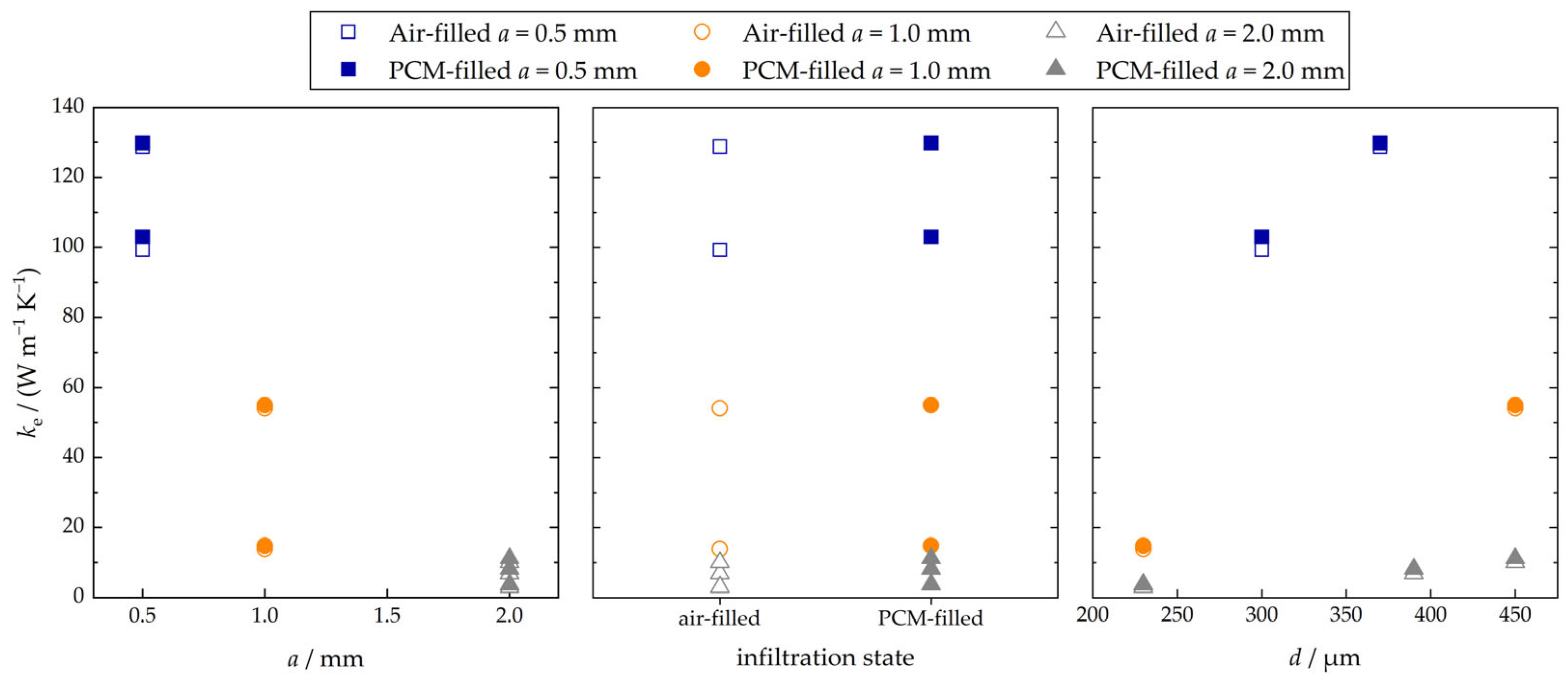
The effective thermal conductivity was obtained through measurements for the seven specimen pairs in air-filled and PCM-filled configurations. The measured values are illustrated in
Figure 7 in dependency of the cell size, the infiltration state, and the strut diameter. It can be stated that, within the considered parameter limits, the effective thermal conductivity exhibits a high dependency on the cell size (negative correlation) and a moderate dependency on the strut diameter (positive correlation). Only slight differences in the effective thermal conductivity between air-filled and PCM-filled configurations were observed. The infiltration of the PCM led to an increase in the experimentally obtained effective thermal conductivity of a minimum of 0.8% for specimen pair 4 (
) and a maximum of 25.3% for specimen pair 5 (
). The lower the relative density of the lattice, the higher the observed relative increase in the effective thermal conductivity is.
The experimental results are listed alongside the numerically obtained results in
Table 6. The comparison mainly demonstrates a good agreement between measurement and simulation data. For the specimen pairs 1, 3, 4, 5, and 6, the relative deviation is found to be below 10%. The relative deviation between measurement and simulation for specimen pairs 2 and 7 amounts to 28.8% and 23.1% for the air-filled configuration (17.5% and 17.8% for the PCM-filled configuration), respectively. Very high deviations of up to 53.8% occurred with respect to the measurements conducted prior to the grinding of the specimens (see
in
Table 6). This implies poor initial contact conditions between the specimens and the TPS sensor due to the rough surface caused by the manufacturing process.
In
Figure 8, the experimentally and numerically obtained values for the effective thermal conductivity are illustrated in dependency of the relative density. In addition, the Ashby lower bound and the HS upper bound are used to calculate the corresponding values. It can be stated that the Ashby lower bound provides a very good estimation for the effective thermal conductivity for
. For
, the experimentally and numerically obtained values are found between both bounds. The deviations in this range are over 28% for the HS upper bound and over 35% for the Ashby lower bound. Thus, a precise prediction of the effective thermal conductivity for the manufactured lattice structures cannot be achieved by means of the Ashby lower bound and HS upper bound.
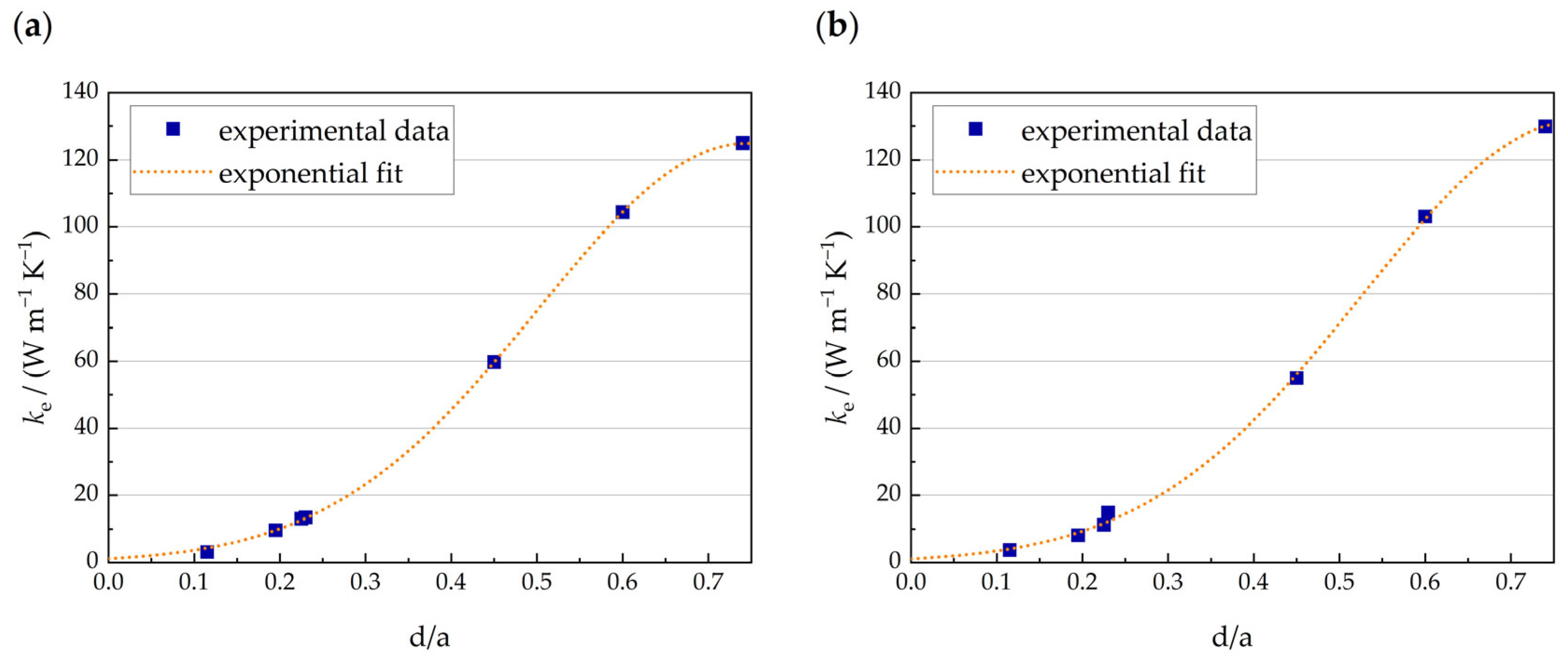
Based on the measurements, an exponential fit was proposed to calculate the effective thermal conductivity using the function
Using the Levenberg–Marquardt algorithm, the regression parameters were obtained with
A = 0.12838,
B = 12.607, and
C = −8.4547 for the air-filled configuration and
A = 0.092708,
B = 12.297, and
C = −7.8972 for the PCM-filled configuration. As illustrated in
Figure 9, the regression functions represent the experimental data with high precision. The exponential fits exhibit coefficients of determination of
0.99989 (air-filled) and
0.99939 (PCM-filled).
4. Discussion
The experimental and numerical examinations of the heat-transfer characteristics of the fabricated lattices led to consistent findings on the effect of the varied geometric parameters. The highest deviations between the experimentally and numerically obtained results were found for specimen pairs 2 and 7, which exhibit a cell size of 2 mm and a low specific density of 0.16 and 0.22, respectively. Hence, the low contact surface areas between the specimens and the sensor are a potential cause of measurement inaccuracy. This assertion is affirmed by the increased agreement between simulation and experiment for specimen pairs 2 and 7 in the PCM-filled configuration, as the aluminum–PCM composite provides a continuous contact area and therefore potentially an enhanced heat transfer into the specimens. Another consequence of the infiltrated PCM is the prevention of convection effects on the inner surface of the lattice, potentially increasing the measurement precision.
The relevance of the quality of the outer specimen surfaces becomes apparent through the comparison of the experimental results obtained before and after the specimen grinding. This observation is due to rough specimen surfaces, leading to higher thermal contact resistance values and hence to an increased temperature drop at the specimen–sensor interface. Accordingly, the effective heat conductance values measured prior to grinding are significantly below the actual values. While the detailed examination of the surface roughness was not addressed in the present investigations, it can be stated that the specimen grinding with sandpaper of grit size P220 led to a significant increase in the measurement quality, resulting in a good agreement of experimental and numerical results.
The reproducibility of the measurements was ensured by measuring each specimen pair three times. The relative standard deviation was found to be below 1% for all specimen pairs, demonstrating a high degree of reproducibility.
The inaccurate prediction of the effective heat conductance by means of the FE model may be caused by irregularities of the fabricated lattices that are not considered within the CAD model. Such irregularities might occur due to constrictions and powder adhesions at the junctions. Lower or higher cross sections of the fabricated lattices may lead to underestimating or overestimating the effective heat conductance when considering a regular lattice geometry with a constant strut diameter. While the precise adjustment of the desired strut diameters during manufacturing still requires a preliminary process parameter identification, the reproducibility of the obtained geometries was found to be high, as observed using optical microscopy. This applies also to the occurrence of lattice irregularities such as powder adhesions with respect to different unit cells within one specimen as well as the comparison between different specimens. However, more detailed investigations, using methods like computed tomography scanning, need to be conducted to further evaluate the geometric accuracy of the manufactured specimens. It is expected that a comprehensive knowledge of the lattice diameter deviations leads to an increased prediction quality when using thermal FE models.
Furthermore, the results demonstrate that it is possible to predict the heat-transfer characteristics of lattice structures manufactured using LPBF by means of analytical approximations. For aluminum lattices with a specific density greater than 0.6, the Ashby lower bound was found to provide a convenient approximation. As the Ashby lower bound in the work of Ohsenbrügge et al. was considered a good estimation of the effective thermal conductivity of closed-cell aluminum foams [
32], it can be stated that both structure types, aluminum BCC lattices and closed-cell aluminum foams, exhibit similar heat-transfer characteristics at a congruent specific density.
5. Conclusions
The present work deals with the thermal characterization of aluminum lattice structures. Regular aluminum lattice structures were manufactured using LPBF. The process parameters were varied to create lattice structures of different strut diameters and BCC unit cell sizes. The effective thermal conductivity of seven specimen pairs was obtained based on the TPS method. To assess the thermal characteristics of lattice structures as a composite matrix in latent heat storage systems, the specimens were infiltrated with a paraffin-based PCM. The measurements were repeated on the resulting composite structures. In addition to the measurements, the effective thermal conductivity of the lattices was obtained numerically by means of FE models.
The findings of the investigation can be summarized as follows:
The experimental data demonstrate the influence of the strut diameter and the unit cell size on the heat-transfer characteristics of the manufactured lattices. The specimen infiltration with PCM led to a small increase in the effective heat conductivity in dependency of the lattice density. The experimentally obtained effective thermal conductivity can be formulated as an exponential function of the diameter-to-unit cell size ratio.
During the measurements, the roughness of the outer specimen surface was found to have a high impact on measurement precision.
The results obtained by means of FE simulation were mainly found to be in good agreement with the experimental data. For specimens with a low specific density, the simulations overestimated the measured effective thermal conductivity, implying a potential effect of lattice irregularities.
The comparison of the measurement data with previously published findings indicates similar heat-transfer characteristics of aluminum BCC lattices and closed-cell aluminum foams.
With respect to the application of aluminum lattice structures in latent heat storage systems, a central design task is determining the appropriate lattice density that provides adequate heat transfer as well as sufficient volume for the PCM infiltration. As an increased density leads to an enhanced heat transfer and, at the same time, reduced latent heat storage volume, the optimum lattice characteristics depend on the corresponding case-specific requirements. The relationship between geometric and physical parameters obtained in the present study can be employed as a design tool for latent heat storage systems. Due to the geometrical freedom provided by the additive manufacturing of lattice structures, it appears possible to locally adjust the effective thermal conductivity, leading to spatially dependent and anisotropic heat transfer behavior. As a consequence, a more balanced compromise between heat transfer and heat storage performance can be obtained in comparison to conventional approaches that address the heat transfer enhancement in latent heat storage systems. The examination of corresponding lattice structures is suggested as a potential topic for future investigations.
Author Contributions
Conceptualization, H.K., R.S. and I.V.; methodology, H.K., R.S. and I.V.; software, H.K., R.S. and I.V.; validation, H.K., R.S. and I.V.; formal analysis, H.K., R.S. and I.V.; investigation, H.K., R.S. and I.V.; resources, W.-G.D., H.K. and R.S.; writing—original draft preparation, H.K., R.S. and I.V.; writing—review and editing, W.-G.D., H.K., R.S. and I.V.; visualization, H.K., R.S. and I.V.; project administration, W.-G.D.; funding acquisition, W.-G.D. and I.V. All authors have read and agreed to the published version of the manuscript.
Funding
This research was funded by the German Research Foundation (DFG) within the Collaborative Research Centre Transregio 96 (subproject C02).
Data Availability Statement
The raw data supporting the conclusions of this article will be made available by the authors on request.
Conflicts of Interest
The authors declare no conflicts of interest.
References
- Mehling, H.; Cabeza, L.F. Heat and Cold Storage with PCM; Springer: Berlin, Germany, 2008. [Google Scholar]
- Aziz, S.; Talha, T.; Mazhar, A.R.; Ali, J.; Jung, D.-W. A Review of Solar-Coupled Phase Change Materials in Buildings. Materials 2023, 16, 5979. [Google Scholar] [CrossRef]
- Browne, M.C.; Norton, B.; McCormack, S.J. Phase change materials for photo-voltaic thermal management. Renew. Sustain. Energy Rev. 2015, 47, 762–782. [Google Scholar] [CrossRef]
- Yan, Y.; Li, W.; Zhu, R.; Lin, C.; Hufenus, R. Flexible Phase Change Material Fiber: A Simple Route to Thermal Energy Control Textiles. Materials 2021, 14, 401. [Google Scholar] [CrossRef] [PubMed]
- Cui, Y.; Liu, C.; Hu, S.; Yu, X. The experimental exploration of carbon nanofiber and carbon nanotube additives on thermal behavior of phase change materials. Sol. Energy Mater. Sol. Cells 2011, 95, 1208–1212. [Google Scholar] [CrossRef]
- Kim, I.H.; Sim, H.W.; Hong, H.H.; Kim, D.W.; Lee, W.; Lee, D.K. Effect of filler size on thermal properties of paraffin/silver nanoparticle composites. Korean J. Chem. Eng. 2019, 36, 1004–1012. [Google Scholar] [CrossRef]
- Al-Maghalseh, M.; Mahkamov, K. Methods of heat transfer intensification in PCM thermal storage systems: Review paper. Renew. Sustain. Energy Rev. 2018, 92, 62–94. [Google Scholar] [CrossRef]
- Schmerler, R.; Gebken, T.; Kühn, M.; Drossel, W.-G. Multifunctional FRP-Aluminum Foam Production Setup for Battery Housings of Electric Vehicles. TLS 2020, 4, 9–17. [Google Scholar] [CrossRef]
- Takarazawa, S.; Ushijima, K.; Fleischhauer, R.; Kato, J.; Terada, K.; Cantwell, W.J.; Kaliske, M.; Kagaya, S.; Hasumoto, S. Heat-transfer and pressure drop characteristics of micro-lattice materials fabricated by selective laser metal melting technology. Heat Mass Transf. 2022, 58, 125–141. [Google Scholar] [CrossRef]
- Bracconi, M.; Ambrosetti, M.; Maestri, M.; Groppi, G.; Tronconi, E. Analysis of the effective thermal conductivity of isotropic and anisotropic Periodic Open Cellular Structures for the intensification of catalytic processes. Chem. Eng. Process. 2020, 158, 108169. [Google Scholar] [CrossRef]
- Wong, M.; Owen, I.; Sutcliffe, C.J.; Puri, A. Convective heat transfer and pressure losses across novel heat sinks fabricated by Selective Laser Melting. Int. J. Heat Mass Transf. 2009, 52, 281–288. [Google Scholar] [CrossRef]
- Rehme, O. Cellular Design for Laser Freeform Fabrication. Ph.D. Thesis, Technische Universität Hamburg-Harburg, Hamburg, Germany, 2009. [Google Scholar]
- Červinek, O.; Werner, B.; Koutný, D.; Vaverka, O.; Pantělejev, L.; Paloušek, D. Computational Approaches of Quasi-Static Compression Loading of SS316L Lattice Structures Made by Selective Laser Melting. Materials. 2021, 14, 2462. [Google Scholar] [CrossRef] [PubMed]
- Du, Y.; Gu, D.; Xi, L.; Dai, D.; Gao, T.; Zhu, J.; Ma, C. Laser additive manufacturing of bio-inspired lattice structure: Forming quality, microstructure and energy absorption behavior. Mater. Sci. Eng. A 2020, 773, 138857. [Google Scholar] [CrossRef]
- Mantovani, S.; Giacalone, M.; Merulla, A.; Bassoli, E.; Defanti, S. Effective Mechanical Properties of AlSi7Mg Additively Manufactured Cubic Lattice Structures. 3D Print. Addit. Manuf. 2022, 9, 326–336. [Google Scholar] [CrossRef]
- Guaglione, F.; Caprio, L.; Previtali, B.; Demir, A.G. Single point exposure LPBF for the production of biodegradable Zn-alloy lattice structures. Addit. Manuf. 2021, 48, 102426. [Google Scholar] [CrossRef]
- Zhong, H.Z.; Li, C.W.; Das, R.; Gu, J.F.; Qian, M. Post-yield softening of bending-dominated metal metamaterials. PNAS Nexus 2023, 2, pgad075. [Google Scholar] [CrossRef] [PubMed]
- Zhang, C.; Banerjee, A.; Hoe, A.; Tamraparni, A.; Felts, J.R.; Shamberger, P.J.; Elwany, A. Design for laser powder bed additive manufacturing of AlSi12 periodic mesoscale lattice structures. Int. J. Adv. Manuf. Technol. 2021, 113, 3599–3612. [Google Scholar] [CrossRef]
- ASTM F3318; Standard for Additive Manufacturing—Finished Part Properties—Specification for AlSi10Mg with Powder Bed Fusion—Laser Beam. ASTM International: West Conshohocken, PA, USA, 2018.
- Korn, H.; Koch, P.; Kordaß, R.; Holtzhausen, S.; Schöne, C.; Müller, B.; Stelzer, R. Adapted Scan Strategy and Slicing Tool for Improvement of Strut Precision in Lattice Structures. In Proceedings of the 2018 ASPE and Euspen Summer Topical Meeting: Advancing Precision in Additive Manufacturing, Berkeley, CA, USA, 22–25 July 2018; pp. 50–55. [Google Scholar]
- Straub, T.; Fell, J.; Zabler, S.; Gustmann, T.; Korn, H.; Fischer, S.C.L. Characterization of Filigree Additively Manufactured NiTi Structures Using Micro Tomography and Micromechanical Testing for Metamaterial Material Models. Materials 2023, 16, 676. [Google Scholar] [CrossRef] [PubMed]
- Rubitherm Technologies, RT50, Data Sheet, October 2020. Available online: https://www.rubitherm.eu/media/products/datasheets/Techdata_-RT50_EN_09102020.PDF (accessed on 6 November 2023).
- Losada-Pérez, P.; Tripathi, C.S.P.; Leys, J.; Cordoyiannis, G.; Glorieux, C.; Thoen, J. Measurements of Heat Capacity and Enthalpy of Phase Change Materials by Adiabatic Scanning Calorimetry. Int. J. Thermophys. 2011, 32, 913–924. [Google Scholar] [CrossRef]
- DIN EN ISO 22007-2:2015-12; Kunststoffe-Bestimmung der Wärmeleitfähigkeit und der Temperaturleitfähigkeit-Teil_2: Transientes Flächenquellenverfahren (Hot-Disk-Verfahren) (ISO_22007-2:2015), Deutsche Fassung. DIN: Berlin, Germany, 2015.
- Hot Disk. Hot Disk Thermal Constants Analyser Handbuch: C3 Prozessund Analysetechnik GmbH; Revisionsdatum 2020; Hot Disk: Gothenburg, Sweden, 2020. [Google Scholar]
- Skibina, V. Bestimmung der Wärmeleitfähigkeit von Nichtdurchströmten Zellularen Metallen. Ph.D. Thesis, Technische Universität Bergakademie Freiberg, Freiberg, Germany, 2013. [Google Scholar]
- Laschet, G.; Sauerhering, J.; Reutter, O.; Fend, T.; Scheele, J. Effective permeability and thermal conductivity of open-cell metallic foams via homogenization on a microstructure model. Comput. Mater. Sci. 2009, 45, 597–603. [Google Scholar] [CrossRef]
- Solórzano, E.; Reglero, J.A.; Rodríguez-Pérez, M.A.; Lehmhus, D.; Wichmann, M.; de Saja, J.A. An experimental study on the thermal conductivity of aluminium foams by using the transient plane source method. Int. J. Heat Mass Transf. 2008, 51, 6259–6267. [Google Scholar] [CrossRef]
- Takezawa, A.; Kobashi, M.; Koizumi, Y.; Kitamura, M. Porous metal produced by selective laser melting with effective isotropic thermal conductivity close to the Hashin–Shtrikman bound. Int. J. Heat Mass Transf. 2017, 105, 564–572. [Google Scholar] [CrossRef]
- Hashin, Z.; Shtrikman, S. A variational approach to the theory of the elastic behaviour of multiphase materials. J. Mech. Phys. Solids 1963, 11, 127–140. [Google Scholar] [CrossRef]
- Ashby, M.F.; Seymour, C.J.; Cebon, D. A database of metal foams and honeycombs. In Metallschäume; Banhart, J., Ed.; Metall Innovation Technologie MIT: Bremen, Germany, 1997; pp. 199–216. [Google Scholar]
- Ohsenbrügge, C.; Marth, W.; y de Sosa, I.N.; Drossel, W.-G.; Voigt, A. Reduced material model for closed cell metal foam infiltrated with phase change material based on high resolution numerical studies. Appl. Therm. Eng. 2016, 94, 505–512. [Google Scholar] [CrossRef]
Figure 1.
BCC unit cell and specimen dimensions. Geometric parameters strut diameter d and unit cell size a are labelled.
Figure 1.
BCC unit cell and specimen dimensions. Geometric parameters strut diameter d and unit cell size a are labelled.
Figure 2.
(a) Different possible scanning strategies considered during manufacturing: (I) point-like scanning, (II) line scanning, (III) cross scanning, and (IV) transversal scanning. (b) Detailed view of the struts of the manufactured specimens.
Figure 2.
(a) Different possible scanning strategies considered during manufacturing: (I) point-like scanning, (II) line scanning, (III) cross scanning, and (IV) transversal scanning. (b) Detailed view of the struts of the manufactured specimens.
Figure 3.
Partial specific enthalpy of PCM RT50 according to manufacturer data [
22].
Figure 3.
Partial specific enthalpy of PCM RT50 according to manufacturer data [
22].
Figure 4.
PCM infiltration method (a) and infiltrated specimen 2–7 (b).
Figure 4.
PCM infiltration method (a) and infiltrated specimen 2–7 (b).
Figure 5.
TPS measurement setup for thermal conductivity investigations.
Figure 5.
TPS measurement setup for thermal conductivity investigations.
Figure 6.
FE model of aluminum lattice (a) and lattice infiltrated with PCM (b), and corresponding meshes with PCM (c) and without PCM (d).
Figure 6.
FE model of aluminum lattice (a) and lattice infiltrated with PCM (b), and corresponding meshes with PCM (c) and without PCM (d).
Figure 7.
Experimentally obtained effective thermal conductivity values in dependency of the cell size, the infiltration state, and the strut diameter.
Figure 7.
Experimentally obtained effective thermal conductivity values in dependency of the cell size, the infiltration state, and the strut diameter.
Figure 8.
Experimentally and numerically obtained effective thermal conductivity in dependency of the relative density for air-filled (a) and PCM-filled lattices (b).
Figure 8.
Experimentally and numerically obtained effective thermal conductivity in dependency of the relative density for air-filled (a) and PCM-filled lattices (b).
Figure 9.
Exponential fits of the effective thermal conductivity obtained through measurements for air-filled (a) and PCM-filled lattices (b) as a function of the diameter-to-unit cell size ratio.
Figure 9.
Exponential fits of the effective thermal conductivity obtained through measurements for air-filled (a) and PCM-filled lattices (b) as a function of the diameter-to-unit cell size ratio.
Table 1.
Specification of the LPBF machine used for manufacturing the specimens.
Table 1.
Specification of the LPBF machine used for manufacturing the specimens.
| | Parameter | Value |
|---|
| Laser | Optics | F-Theta |
| Beam profile | Gaussian |
| Max. power | 400 W |
| Min. focus | 35 µm |
| Process | Atmosphere | Nitrogen |
| Preheating | 200 °C |
| Recoating sequence | Bidirectional (along x-axis) |
| Recoater type | Silicone lip |
| Powder management | Closed loop |
| Gas stream | Along y-axis |
| Layer height | 25 µm |
Table 2.
Fabricated specimens with corresponding geometric parameters.
Table 2.
Fabricated specimens with corresponding geometric parameters.
| Specimens | Parameter Set | /mm | /µm | | |
|---|
| 1-1 and 2-1 | A | 0.5 | 300 | 0.90 | 0.90 |
| 1-2 and 2-2 | A | 2.0 | 390 | 0.17 | 0.16 |
| 1-3 and 2-3 | C | 1.0 | 450 | 0.66 | 0.65 |
| 1-4 and 2-4 | C | 0.5 | 370 | 0.99 | 0.99 |
| 1-5 and 2-5 | B | 2.0 | 230 | 0.06 | 0.07 |
| 1-6 and 2-6 | B | 1.0 | 230 | 0.23 | 0.24 |
| 1-7 and 2-7 | C | 2.0 | 450 | 0.22 | 0.22 |
Table 3.
Parameter sets with corresponding process parameters used during LPBF manufacturing.
Table 3.
Parameter sets with corresponding process parameters used during LPBF manufacturing.
| Parameter Set | A | B | C |
|---|
| Laser power/W | 200 | 150 | 180 |
| Scan speed/(mm/s) | 179 | 1000 | 257 |
| Focus diameter/µm | 150 | 55 | 55 |
Table 4.
Enthalpy difference between 43 °C and 58 °C of the air-filled and PCM-filled lattices as well as corresponding lattice and PCM mass.
Table 4.
Enthalpy difference between 43 °C and 58 °C of the air-filled and PCM-filled lattices as well as corresponding lattice and PCM mass.
| Specimens | | /g | /g | /J | /J |
|---|
| 1-1 and 2-1 | 0.90 | 137 | 2 | 1808 | 2128 |
| 1-2 and 2-2 | 0.16 | 24 | 40 | 317 | 6717 |
| 1-3 and 2-3 | 0.65 | 98 | 15 | 1294 | 3694 |
| 1-4 and 2-4 | 0.99 | 147 | 0 | 1940 | 1940 |
| 1-5 and 2-5 | 0.07 | 11 | 47 | 145 | 7665 |
| 1-6 and 2-6 | 0.24 | 35 | 36 | 462 | 6222 |
| 1-7 and 2-7 | 0.22 | 33 | 37 | 436 | 6356 |
Table 5.
TPS measurement parameters.
Table 5.
TPS measurement parameters.
| Specimens | Air-Filled, before Grinding | Air-Filled, after Grinding | PCM-Filled |
|---|
| Power/W | Time/s | Power/W | Time/s | Power/W | Time/s |
|---|
| 1-1 and 2-1 | 0.90 | 3 | 2.20 | 1 | 3.00 | 1 |
| 1-2 and 2-2 | 0.15 | 5 | 0.30 | 4 | 0.60 | 10 |
| 1-3 and 2-3 | 1.00 | 3 | 1.80 | 2 | 3.00 | 2 |
| 1-4 and 2-4 | 1.60 | 1 | 3.30 | 1 | 4.50 | 1 |
| 1-5 and 2-5 | 0.15 | 5 | 0.30 | 4 | 0.50 | 20 |
| 1-6 and 2-6 | 0.30 | 3 | 0.50 | 2 | 0.50 | 2 |
| 1-7 and 2-7 | 0.15 | 5 | 0.50 | 3 | 0.50 | 3 |
Table 6.
Experimentally and numerically obtained values for the effective thermal conductivity of the specimens in air-filled and PCM-filled configurations. denotes the values measured prior to specimen grinding.
Table 6.
Experimentally and numerically obtained values for the effective thermal conductivity of the specimens in air-filled and PCM-filled configurations. denotes the values measured prior to specimen grinding.
| Specimens | Air-Filled | PCM-Filled |
|---|
| /(W/(m·K)) | /(W/(m·K)) | /(W/(m·K)) | /(W/(m·K)) | /(W/(m·K)) |
|---|
| 1-1 and 2-1 | 48.18 | 99.33 | 104.38 | 103.05 | 104.67 |
| 1-2 and 2-2 | 4.64 | 6.85 | 9.625 | 8.12 | 9.84 |
| 1-3 and 2-3 | 37.95 | 54.02 | 59.75 | 54.98 | 60.56 |
| 1-4 and 2-4 | 79.85 | 128.90 | 124.98 | 129.90 | 124.98 |
| 1-5 and 2-5 | 2.13 | 2.96 | 3.13 | 3.71 | 3.45 |
| 1-6 and 2-6 | 10.36 | 13.86 | 13.42 | 14.81 | 15.37 |
| 1-7 and 2-7 | 6.04 | 10.02 | 13.03 | 11.20 | 13.63 |
| Disclaimer/Publisher’s Note: The statements, opinions and data contained in all publications are solely those of the individual author(s) and contributor(s) and not of MDPI and/or the editor(s). MDPI and/or the editor(s) disclaim responsibility for any injury to people or property resulting from any ideas, methods, instructions or products referred to in the content. |
© 2024 by the authors. Licensee MDPI, Basel, Switzerland. This article is an open access article distributed under the terms and conditions of the Creative Commons Attribution (CC BY) license (https://creativecommons.org/licenses/by/4.0/).


