Article

Processing of Thin Films Based on Cellulose Nanocrystals and Biodegradable Polymers by Space-Confined Solvent Vapor Annealing and Morphological Characteristics

1
Research Institute for Analytical Instrumentation Subsidiary, National Institute for Research and Development of Optoelectronics Bucharest INOE 2000, 67 Donath Street, 400293 Cluj-Napoca, Romania
2
Interdisciplinary Research Institute on Bio-Nano-Sciences, Babeș-Bolyai University, 400271 Cluj-Napoca, Romania
3
Department of Physics of Condensed Matter and Advanced Technologies, Faculty of Physics, Babeș-Bolyai University, 400084 Cluj-Napoca, Romania
4
National Institute for Research and Development of Isotopic and Molecular Technologies, 67-103 Donath Street, 400293 Cluj-Napoca, Romania
*
Authors to whom correspondence should be addressed.
Materials 2024, 17(7), 1685; https://doi.org/10.3390/ma17071685
Submission received: 12 March 2024 / Revised: 29 March 2024 / Accepted: 4 April 2024 / Published: 7 April 2024
(This article belongs to the Special Issue Sustainable Materials from Industrial Waste)

Abstract

:
L-poly(lactic acid), poly(3-hydroxybutyrate), and poly-hydroxybutyrate-co-hydroxyvalerate are biodegradable polymers that can be obtained from renewable biomass sources. The aim of this study was to develop three types of environmentally friendly film biocomposites of altered microstructure by combining each of the above-mentioned polymers with cellulose nanocrystal fillers and further processing the resulting materials via space-confined solvent vapor annealing. Cellulose was previously obtained from renewable biomass and further converted to cellulose nanocrystals by hydrolysis with the lactic acid. The solutions of biodegradable polymers were spin-coated onto solid substrates before and after the addition of cellulose nanocrystals. The obtained thin film composites were further processed via space-confined solvent vapor annealing to eventually favor their crystallization and, thus, to alter the final microstructure. Indeed, atomic force microscopy studies have revealed that the presence of cellulose nanocrystals within a biodegradable polymer matrix promoted the formation of large crystalline structures exhibiting fractal-, spherulitic- or needle-like morphologies.

1. Introduction

Lignocellulosic biomass is a substantial resource of cellulose, a material that can act as a filler in a variety of bioplastic composites. A critical review on the incorporation of biomass, such as cellulose, hemicellulose or lignin, into PLA was recently published in the literature [1].
Due to the poor interfacial adhesion with thermoplastics, it is necessary to modify the lignocellulosic components. This can be achieved through chemical, physical, or enzymatic modification of the cellulose and hemicellulose surfaces [2,3,4]. In contrast, the structure of lignin can be altered by dissolving it in organic solvents or by adding nucleating agents [1]. To be used as a filler, cellulose must undergo hydrolysis to obtain nanocrystals, fibrillated cellulose, regenerated cellulose, or other cellulose derivatives [5]. The semicrystalline structure of cellulose is due to the presence of three hydroxyl groups that form intra- and intermolecular bonds. Nanocrystalline cellulose is a green material with advanced chemical, optical, and mechanical properties [6,7]. Cellulose can be used as a filler in various biocomposites. However, it must first be isolated from lignocellulosic waste and transformed into micro/nanofibers, nanocrystalline (nanowhiskers/nanowires), or bacterial cellulose [8,9]. Resulting cellulose nanocrystals and nanofibers could then be also used as reinforcement in inks for additive manufacturing [10]. Also, it is important to mention that using strong acids for hydrolysis is generally leading to a decrease in the crystallinity of cellulose, while weak acids (such as oxalic, formic, and lactic acids) could increase the crystallinity of cellulose and lead to nanocellulose with high thermal stability and suitable properties for producing biocomposites [11]. Thus, natural fibers (e.g., cellulose) and biodegradable polymers can generate together strong, environmentally friendly biomaterials that can be used in specific applications such as food packaging, computer keyboards, automotive interior parts, or in the medical field [12].
Polymerization is a process of covalent attachment of various monomers into long polymeric chains [13,14], with their physical, chemical, and thermal properties strongly depending on the type of monomer constituents [15,16,17,18]. Therefore, polymers can have different applications across a wide range of fields [19,20,21,22,23,24,25]. In particular, biodegradable polymers find applications in various domains (cosmetics, coatings, medicine, etc.) due to their environmentally friendly nature and the increasing emphasis on sustainability [26,27,28,29]. Moreover, biodegradable polymer thin films are commonly used in packaging, agriculture, medical, water treatment, and construction applications [30]. In these sectors, biodegradable polymers will hopefully completely replace classic petroleum-based plastics in the future.
Polyhydroxyalkanoates are thermoplastic polyesters along with other biomacromolecules, such as poly(3-hydroxybutyrate) (P3HB), polyhydroxy valerate (PHV), poly-hydroxybutyrate-co-hydroxyvalerate (PHBV), just to name a few, that are obtained from renewable biomass (lignocellulosic waste, trees, vegetables, plants, grasses, etc.) [31,32]. While P3HB and PHBV have many advantages regarding biodegradability, biocompatibility, and non-toxicity, they also exhibit some disadvantages related to low stability, poor mechanical strength, and slow nucleation rate [33]. Improved biocomposites can be obtained by combining different biopolymers with natural fibers produced from renewable resources, such as hemp, cotton, bamboo, sugarcane, etc. [34,35]. For instance, P3HB is an amorphous polymer with many applications in fields such as storage of food products [36], surgical sutures, wound dressing [37], and controlled-release drug delivery systems [38]. It is obtained by fermentation of carbohydrate sources in the presence of microorganisms (Bacillus spp., Pseudomonas spp., Ralstonia eutropha, Escherichia coli, etc.) [39]. The P3HB-based biocomposites can have applications in the packaging industry, sensors, enzyme carriers, biomedical implants, etc. [40,41,42,43]. Moreover, it has been found that polymer-based biocomposites have better strength and elongation properties than their neat polymeric analogues [44]. Examples include the enhanced P3HB-based biocomposites obtained through the incorporation of modified wheat straw flour [45], cellulose [46], or wood waste fibers [47] into the P3HB matrix. Furthermore, using biomass wastes from food, paper, and forests in the production of biocomposites could further improve the circular economy by reducing greenhouse emissions. Additionally, polysaccharides have been used as fillers in thermoplastics [48,49,50].
For that, polymer–cellulose composite materials have to exhibit good mechanical properties, with the latter being strongly dependent on the composite’s microstructure. Therefore, in order to tune the mechanical properties of biocomposites made of different biopolymeric materials and cellulose, one has to be able to manipulate/alter the resulting microstructure by modifying the molecular arrangements at both the nano- and microscale [51,52]. This can be experimentally implemented by employing different polymer processing methods that can control and adjust the molecular arrangements at various length scales [53,54]. Obviously, the preliminary treatment of (bio)polymer-based solutions and the chosen thin film deposition method will be the primary methods able to impact the initial film microstructure [54,55]. Furthermore, once thin films of (bio)polymer-based composites are fabricated, they can undergo a further processing using specific post-fabrication techniques described in detail elsewhere [54].
In this work, we propose to employ an efficient processing technique called space-confined solvent vapor annealing (C-SVA) [56,57,58,59] to alter the initial spin-coated microstructure of thin films generated from biodegradable L-poly(lactic acid) (PLLA), P3HB and PHBV polymers and cellulose nanocrystals by inducing/favoring the crystallization process in such composite films. By precipitating solvent vapors onto a thin film, the latter becomes massively swollen, allowing constituent polymer chains to move freely and eventually to rearrange and adopt more ordered/crystalline molecular conformations within fractal-, spherulitic-, or needle-like structures.

2. Materials and Methods

2.1. Materials

PLLA, P3HB, and PHBV (Figure 1a–c) were used as raw materials. PLLA was synthesized from lignocellulosic biomass using a previously published method involving pressurized hot water pretreatment of the biomass, simultaneous saccharification and fermentation to lactic acid, followed by polymerization of the lactic acid by microwave irradiation at 140 °C for 30 min using o-xylene as solvent and SnCl2 as catalyst (0.4 wt.%) [52]. The molecular weight of obtained PLLA was 1674 g/mol. P3HB was produced from lignocellulosic biomass using microwave irradiation, ammonia delignification, enzymatic hydrolysis, and fermentation with the Bacillus megaterium ATCC 14581 strain, as described in detail elsewhere [60]. Instead, PHBV containing 8% of 3-hydroxyvalerate was purchased from Sigma-Aldrich (St. Louis, MO, USA). Chloroform was purchased from Merck (Darmstadt, Germany). The cellulose used in this study was obtained from vineyard wastes by autohydrolysis pretreatment (180 °C, 10 min, 10 mPa) and delignification with sodium chlorite according to our previous method [61].

2.2. Production of Cellulose Nanocrystals (CNC)

The cellulose powder (2 g) was immersed in 100 mL of 5 M lactic acid and mechanically stirred at 80 °C for 4 h. The resulting mixture was filtered and washed with water to remove excess acid and water-soluble fragments. Fine CNCs were obtained after centrifugation at 5000 rpm for 30 min. The final powder of CNCs was obtained after drying in a Labconco FreeZone 2.5 L system (Labconco, Kansas City, MO, USA), for 12 h. The CNCs were characterized, and the average length of the CNC particles was found to be 12.2 µm, along with a width of 7 µm. The size of the CNCs was examined using a scanning electron microscope (SEM VEGAS 3 SBU, Tescan, Brno-Kohoutovice, Czech Republic), and crystal conglomerates were observed.

2.3. Production of Polymer/CNC Composites

Each polymer (PLLA, P3HB, and PHBV) was mixed with CNC (0.02 g/g) and dissolved in chloroform. The mixture was homogenized through mechanical stirring while heated up to 70 °C for 3 h. Subsequently, the resulting mixture was dried at room temperature and evaporated inside the fume hood for 24 h. Finally, the solid composite was dried at 60 °C for 24 h.

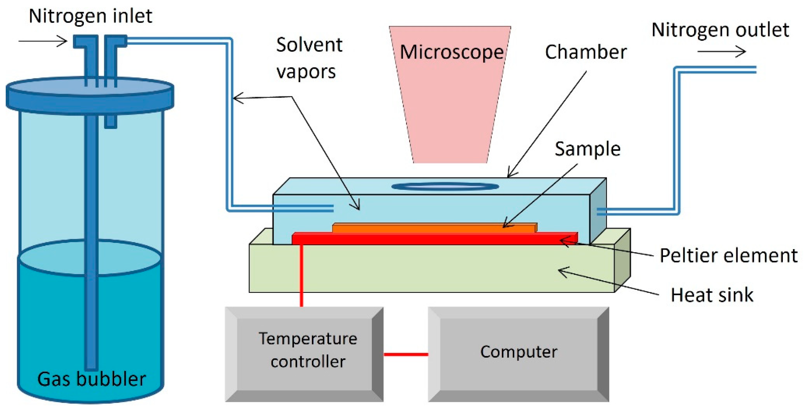
2.4. Processing of Thin Films Based on Cellulose Nanocrystals and Biodegradable Polymers by C-SVA

Thin neat and blended films were deposited on SiO2 wafers by spin-coating at 3000 rpm at room temperature from solutions with a concentration of 6 g/L. The resulting thin films were cut into two pieces. While one half was analyzed as a reference, the other half of the film was further processed using the C-SVA technique and the equipment described in Figure 2. This equipment consists of an aluminum chamber with a high-performance Peltier element at the bottom. On the upper part, there is a cover with a glass window through which the current state of the thin film can be observed in real time and direct space. When a current flows through the Peltier element, one side is heated, and the other side cools down. If the direction of the electric current changes, the hot and cold sides are reversed. The Peltier element is connected to a controller that varies the current and voltage to make the upper side of the Peltier element reach the desired temperature. On the other side, there is a heat sink and a fan, which help in stabilizing the temperature. The Peltier element and heat sink work together to maintain a stable temperature for the bottom of the aluminum chamber (on which film samples are placed). The desired temperature is entered into the controller’s program, which runs on a computer that is connected to the temperature controller. The actual temperature of the bottom of the sample chamber is fed back to the controller by a PT100 temperature sensor, and, therefore, this equipment allows the temperature of the bottom of the sample chamber to be varied between 0 and 100 °C with an accuracy of 0.01 °C. More importantly, the equipment allows the temperature to be changed at a rate as low as 0.01 °C/s. Furthermore, using a bubbler, the organic solvent vapors are introduced into the sample chamber along with the film sample. Then, the temperature of the film sample is reduced, so that the solvent vapors can easily condense onto the film. As a result, the film absorbs a lot of solvent molecules, becomes highly swollen (at this point it becomes a film-solution), and the polymer molecules are free to move. Then the process is reversed; the sample is heated up at a rate of only 0.01 °C/s, and the solvent starts to evaporate very slowly, while the polymer chains have time to adopt rather ordered/altered molecular arrangements.

2.5. Characterization of Biocomposites and Polymers

2.5.1. Atomic Force Microscopy

AFM images of biocomposite films were realized by employing, in the tapping mode, a system from Molecular Devices and Tools for Nano Technology (NT-MDT) mounted on an Olympus IX71 optical microscope (Spectrum Instruments Ltd., Limerick, Ireland). AFM measurements were performed using high-resolution Noncontact Golden Silicon probes from NT-MDT at a scanning speed of about 1–2 μm/s. The set point (of 9–12 V) was adjusted from sample to sample in order to maintain a very soft tapping regime.

2.5.2. Thermogravimetric Analysis/Derivative Thermogravimetry (TGA/DTG) Measurements

Thermal decomposition of samples was realized by using a TA Instruments SDT O 600 equipment (from TA Instruments, New Castle, DE, USA). The samples were heated in air from an initial temperature of 30 °C to 1000 °C at a rate of 10 °C per minute. The maximum weight loss was determined from the DTG curve.

2.5.3. Raman Spectroscopy

Raman spectroscopic measurements were realized by using the PROGENY portable Raman Spectrometer (Rigaku Raman Technologies Inc., Tokyo, Japan) by employing the following parameters: a laser frequency of 1064 nm, a laser power of 490 mW, an exposure time of 7000 ms, and a spectral range of 200–2000 cm−1. The detector used was an InGaAs type with cooling. The exposure time and the number of repetitions were adjusted to ensure the proper noise-to-signal ratio.

2.5.4. Differential Scanning Calorimetry (DSC) Measurements

Thermal calorimetric measurements were performed with a DSC-60 Shimadzu differential scanning calorimeter (Shimadzu Corporation, Kyoto, Japan) in standard aluminum crimped pan as sample holder. About 1.5 mg of material was analyzed under dry nitrogen flow (3.6 L/h) in the 20 to 250 °C temperature range using a scanning rate of 10 °C/min. The alumina was used as reference material. Data collection and analysis were undertaken using the Shimadzu TA-WS60 and TA60 version 2.1 software.

3. Results and Discussion

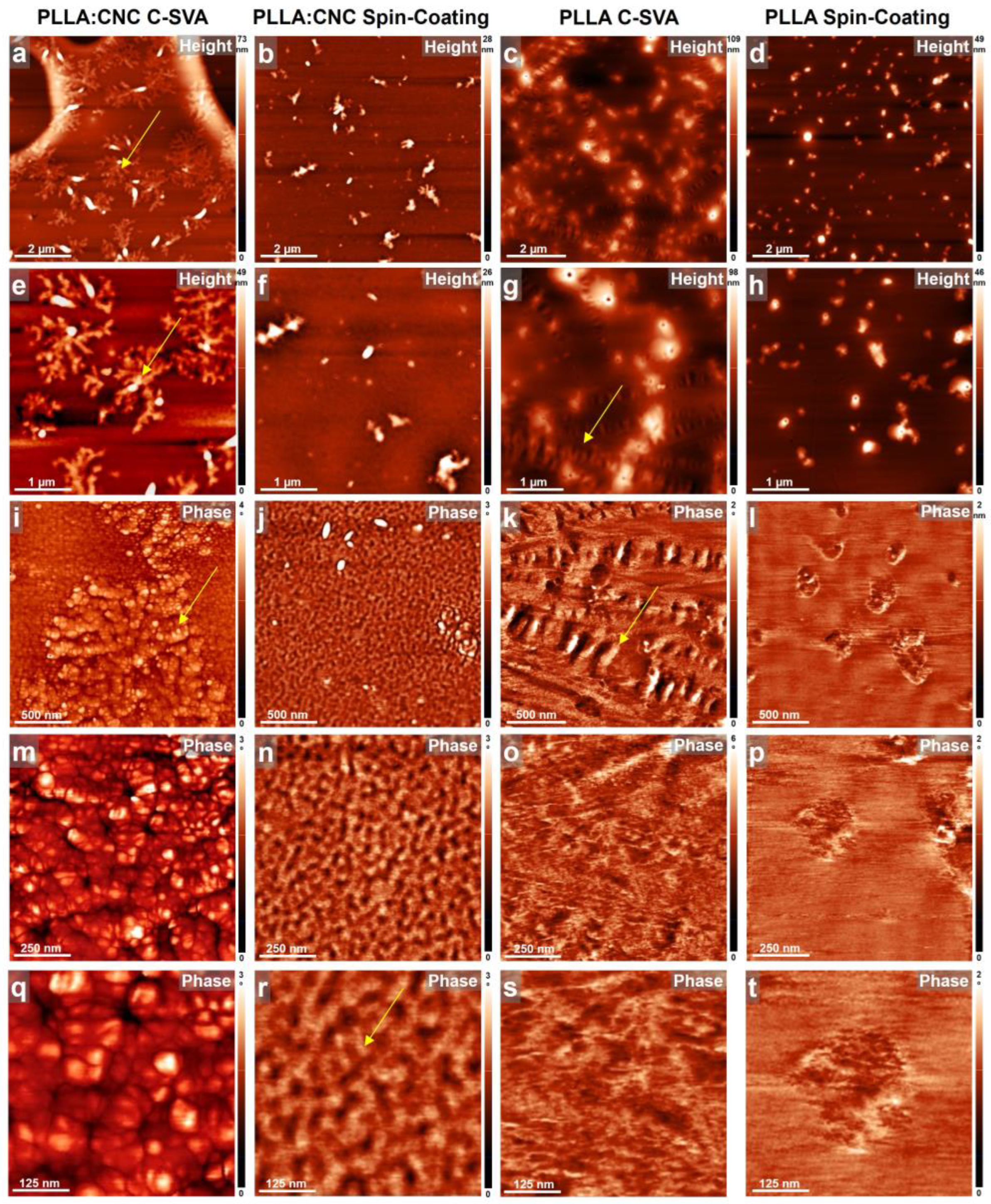
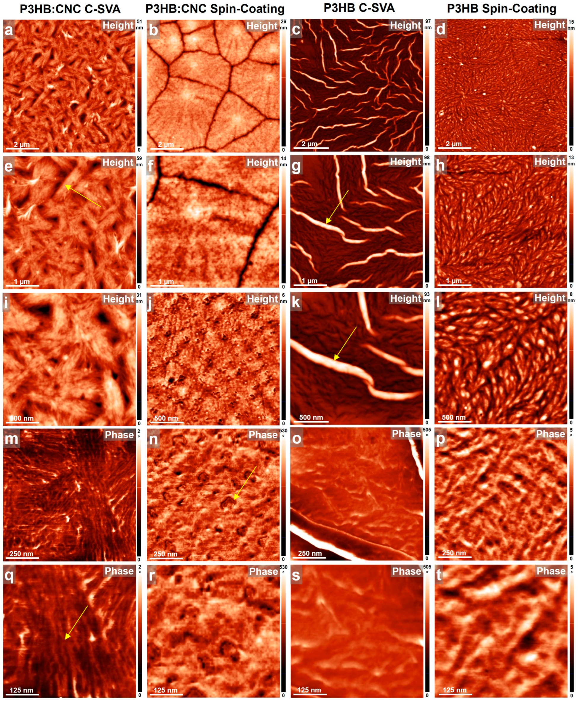
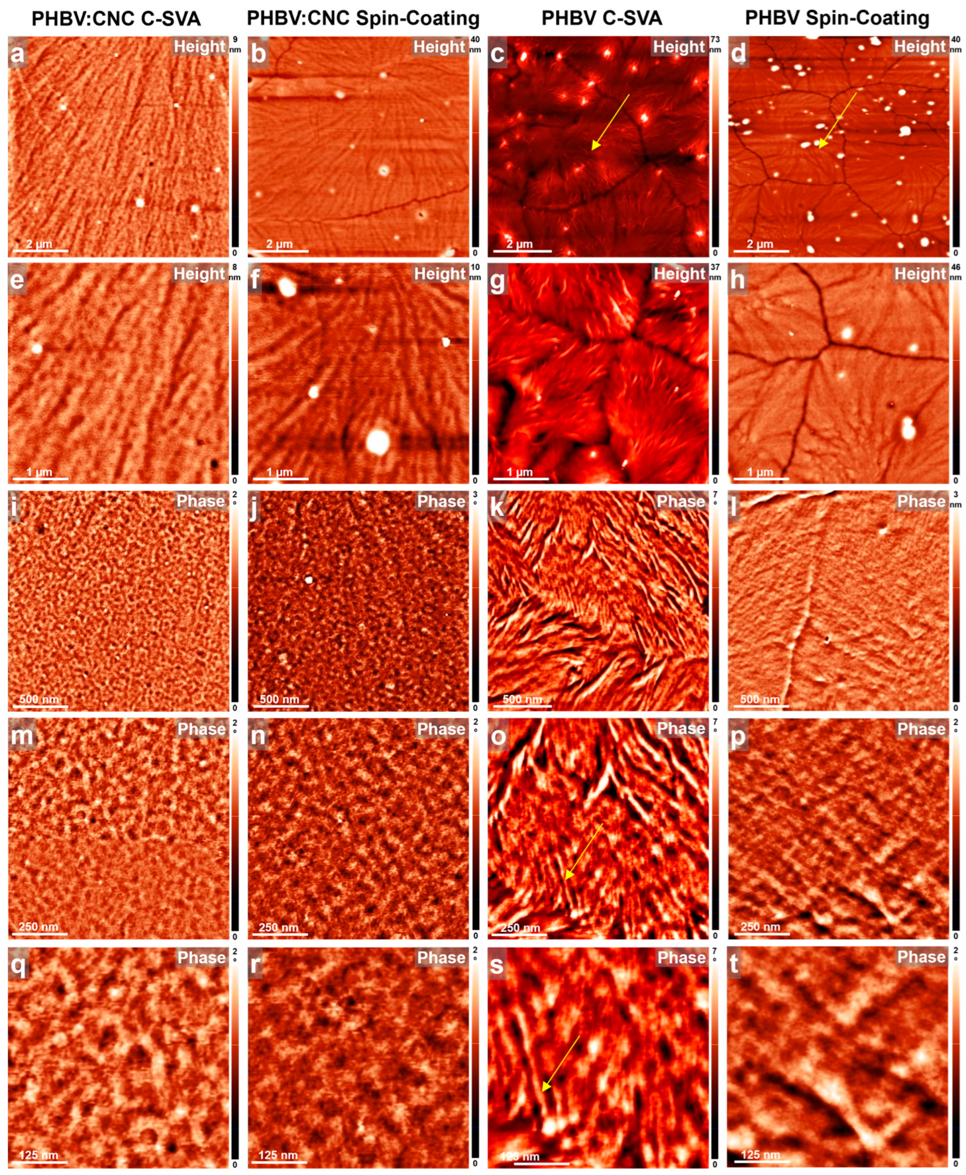
3.1. AFM Studies of Thin Films Produced by C-SVA

Cellulose nanocrystals (CNCs), derived from lignocellulosic biomass and the biodegradable polymers described above, were blended to generate thin film composites (CNC has been obtained from biomass by autohydrolysis pre-treatment methods for cellulose separation and reaction of cellulose with lactic acid to increase its crystallinity). In this way, CNCs can be used as a filler for blending with polymers [59].
All fabricated neat and blended films before and after their processing via C-SVA were further investigated under an AFM, and the obtained results are shown in Figure 3, Figure 4 and Figure 5. These studies have shown that the presence of CNCs in PLLA, P3HB, and PHBV thin films coupled with the C-SVA processing promoted the formation of larger crystalline structures, such as fractal-like crystals (PLLA:CNC), needle-like/elongated structures (P3HB:CNC), or spherulites (PHBV:CNC).
Figure 3 presents AFM height and phase images of both neat PLLA films (on the right) and PLLA:CNC film composites (on the left). CNC-induced crystallization of blended material when undergoing processing via C-SVA can be seen in Figure 3a,e,i,m,q. The resulting structures resembled fractal-like crystals (Figure 3a,e), with their morphology further comprised of rather spherical substructures (Figure 3i) of a diameter of about 50 to 100 nm (Figure 3m,q). Among the fractal-shaped crystals, the surface was covered with nanostructures that have a lateral dimension of only a few tens of nanometers (Figure 3i). This latter morphology was similar to the unprocessed morphology of PLLA:CNC obtained right after the spin-coating (Figure 3j). Obviously the fractal-like crystals were not observed in the unprocessed spin-coated PLLA:CNC films (Figure 3b,f,j). Here, only some irregular aggregates were present; the rest of the surface was covered with small structures of a lateral dimension of less than 50 nm (Figure 3n,r). Moreover, to the best of our knowledge, the fractal-like microstructure of PLLA:CNC has not been reported so far in the literature (while Wang et al. demonstrated that the addition of CNC improved the properties of PLLA films, including crystallinity, tensile strength, and elastic modulus, the AFM images depicted no fractal structures [62]) and attribute its existence to the C-SVA processing. This conclusion is in line with our observations inferred from the AFM studies performed on the PLLA neat films before and after C-SVA processing (compare Figure 3c,g,k to Figure 3d,h,l). Here, the C-SVA processing seemed to often arrange the PLLA macromolecules into 0.3–1.1-micrometer-long structures displayed rather parallel to each other (Figure 3g,k). This was not the case for the unprocessed neat film that exhibited only some randomly distributed aggregates (Figure 3h,l). The nature of these aggregates is most probably amorphous, as there was almost no difference in the phase contrast recorded for the aggregated and the rest of the PLLA-covered surface (Figure 3p,t). Instead, the C-SVA processed PLLA film sometimes displayed lamellar-resembling structures (Figure 3o,s). Therefore, we concluded that in order to obtain fractal-like structures, one has not only to blend PLLA with CNC but also to further process the blended film via C-SVA in order to favor the crystallization/structuring process.
This is particularly important because of the expected strong correlation between the polymeric microstructure and the mechanical or other properties of this material [63].
Our second example of a biodegradable composite was generated by blending P3HB with CNCs. While the P3HB system was previously used in a mixture with PLA and CNCs to increase the crystallinity of PLA [64], its high crystallinity makes it too rigid, stiff, and brittle [65]. Therefore, we have optimized the crystallinity of P3HB to a crystallinity index of 43.1%, making it a semicrystalline polymer. It could thus be interesting to see how such semicrystallinity of P3HB would influence physical characteristics for purposes related to possible bioplastic applications (note that the applicability of P3HB is generally limited due to low ductility, inherent brittleness, and fragility [66]).
Figure 4 presents the surface of a P3HB film, with and without CNCs, before and after its processing via C-SVA. When compared with the PLLA, the P3HB system already generated interesting structures right after the spin-coating process. Here, a morphology most probably generated by the spherulitic growth (Figure 4d,h,l) and comprised of rather large, weakly aligned objects displaying a lateral dimension a few hundreds of nanometers (slightly elongated; Figure 4h,l) was uncovered by AFM. This morphology dramatically changed when the P3HB film was further processed by C-SVA. Now, there were several micrometers-large needle-like structures randomly distributed over the whole surface (Figure 4c,g,k). In between these needle-like structures, the morphology resembled that of unprocessed film (compare Figure 4o,s with Figure 4p,t). Instead, adding CNCs to the P3HB system led to clear spherulitic growth, with grain boundaries clearly visible in AFM images right after the spin-coating (Figure 4b,f). Zooming in on such spherulites revealed that the generated morphology was comprised of small spherical objects (Figure 4j) of a diameter ranging from about 50 to 130 nm (Figure 4n,r). This “spherical” microstructure was very different from the one generated when the P3HB:CNC film was further processed via C-SVA. In the latter case, the morphology was comprised of parallel lamellar structures of a lateral dimension of 24 ± 4 nm. Such lamellae further formed micrometer-long, most probably crystalline, superstructures displaying a rather elongated shape (Figure 4a,e,i).
In our last example, we present the PHBV system with and without CNCs before (i.e., right after the spin-coating) and after its further processing via C-SVA. As was revealed by the AFM technique, this polymeric system was able to produce crystalline structures such as spherulites without any need of CNCs or further processing other than the spincoating. Figure 5d,h illustrates that the crystalline spherulites already started to develop, when the solvent molecules were rapidly evaporating during the spin-coating process and further grew larger at room temperature until the whole reservoir of “available” molecules was exhausted, as is demonstrated by the existence of grain boundaries left behind. A further processing of the spin-coated PHBV film via C-SVA also led to large crystalline spherulites (Figure 5c,g). Nonetheless, the substructures identified in the AFM zoomed-in images exhibited better-defined lamellar/fibrillar structures when compared to the reference unprocessed film (compare Figure 5k,o,s with Figure 5l,p,t). The average lateral dimension of such lamellae was deduced, by analyzing several height cross-sectional profiles in images presented in Figure 5o,s, to be around 30 nm. Furthermore, adding CNCs to PHBV led to the composite films displaying larger spherulites (Figure 5b,f) as compared to the neat polymer films obtained right after the spin-coating process. Even larger spherulites (Figure 5a,e) were observed when the PHBV:CNC film was further processed via C-SVA. Interestingly, in these later cases of unprocessed and processed composite films, the spherulites were not comprised of lamellar substructures as in the case of the processed neat PHBV film, but they contained rather spherically shaped features (compare Figure 5i,m,q and Figure 5j,n,r with Figure 5k,o,s).
All the above experiments indicated that the utilization of CNCs derived from lignocellulose biomass in polymer matrices was favoring crystallization and finally led to various crystalline structures, including fractal-like, needle-like, or spherulitic morphologies, each further displaying additional substructures of molecular dimensions, such as spherical or lamellar/fibrillar features. We expect that these better-crystallized composite films, obtained by blending with CNCs coupled with additional processing via C-SVA, could be further exploited in applications such as environmentally friendly packaging, biomedical and biosensor applications, or drug delivery processes.
In conclusion, while it is not easy to quantify in which case CNCs had the strongest effect because there were significant changes observed in all three cases, the utilization of CNCs with PLLA led to the appearance of fractal-like crystals (as shown in Figure 3), which was not the case for the other two studied composites.
The literature suggests that the preparation method of composite-based polymers affects their crystallization morphology. It is widely accepted that a strong bond between the polymer and the filler leads to improved interfacial adhesion of biocomposites and desirable morphologies [67,68].
Our results indicate that the C-SVA method used in this study induced crystallization of polymer-based composites more effectively than classical methods such as dip-coating, spin-coating, layer-by-layer deposition, and electrospinning [69]. For instance, we could observe crystallization of the PLLA:CNC composite only when employing the C-SVA processing method. Thus, this method improved the crystallization process and led to a higher degree of crystallinity, as will be seen further in the sections below.

3.2. Characterization of the Polymer/CNC Composites
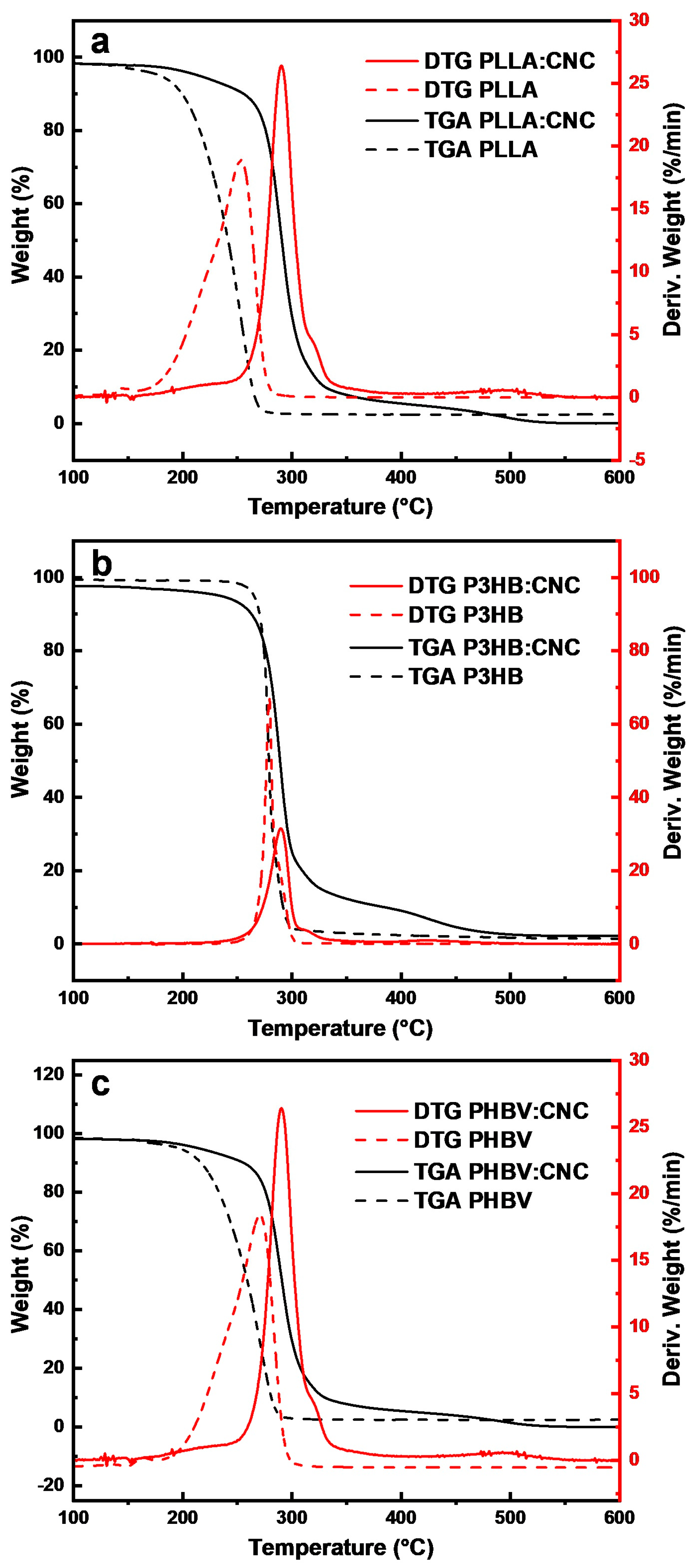
3.2.1. TGA/DTG

Thermal stability of the samples was evaluated by performing experiments on thermal degradation. Figure 6 presents the TGA/DTG curves of the obtained polymer–CNC composites and their corresponding polymers.
The melting point for P3HB was ~279 °C (Figure 6b) and appears as a single maximum, indicating good purity of the P3HB bioplastic [58]. The melting temperature confirms the presence of butyrate units, with no other traces of impurities (the high purity of the P3HB was further indicated by the large mass loss of 98.86%). The TGA of PLLA:CNC (Figure 6a) shows a maximum degradation temperature at ~262 °C, while for P3HB:CNC this temperature was ~290 °C (Figure 6b). Thus, the degradation temperature of PLLA in the PLLA:CNC composite (262 °C) was higher as compared to that of 253 °C measured in neat PLLA. Thus, the thermal stability of PLLA was changed after the blending with CNCs, as demonstrated by the increase of degradation temperature, most probably due to changes in some functional groups induced by treatment with acid [67]. According to Mokhena et al., the type of acids used in the treatment of cellulose influences the thermal stability of resulting composites. Thus, incorporating CNCs in a polymer matrix increases the thermal stability of the resulting composite. Similar results were obtained for P3HB:CNC [70].
The degradation temperature of the PHBV:CNC composite was 290.4 °C (Figure 6c), significantly higher than the maximum degradation temperature of 272 °C observed for neat PHBV. According to the literature [71], the melting temperature for PHBV was 249.4 °C and increased to 276.7 °C in the nanofibrous composite PHBV:CNC-based composite. This is due to the formation of many hydrogen bonds between CNCs and PHBV by dispersion in chloroform. Moreover, for all composites, adding CNCs led to an increased degradation temperature, thus showing a better thermal stability [72]. The TGA curves show that the decomposition of all biocomposites can be divided into two stages. The first weight loss between 30 °C and 200 °C was attributed to water loss. The second main weight loss between 200 °C and 300 °C was related to polymer degradation.

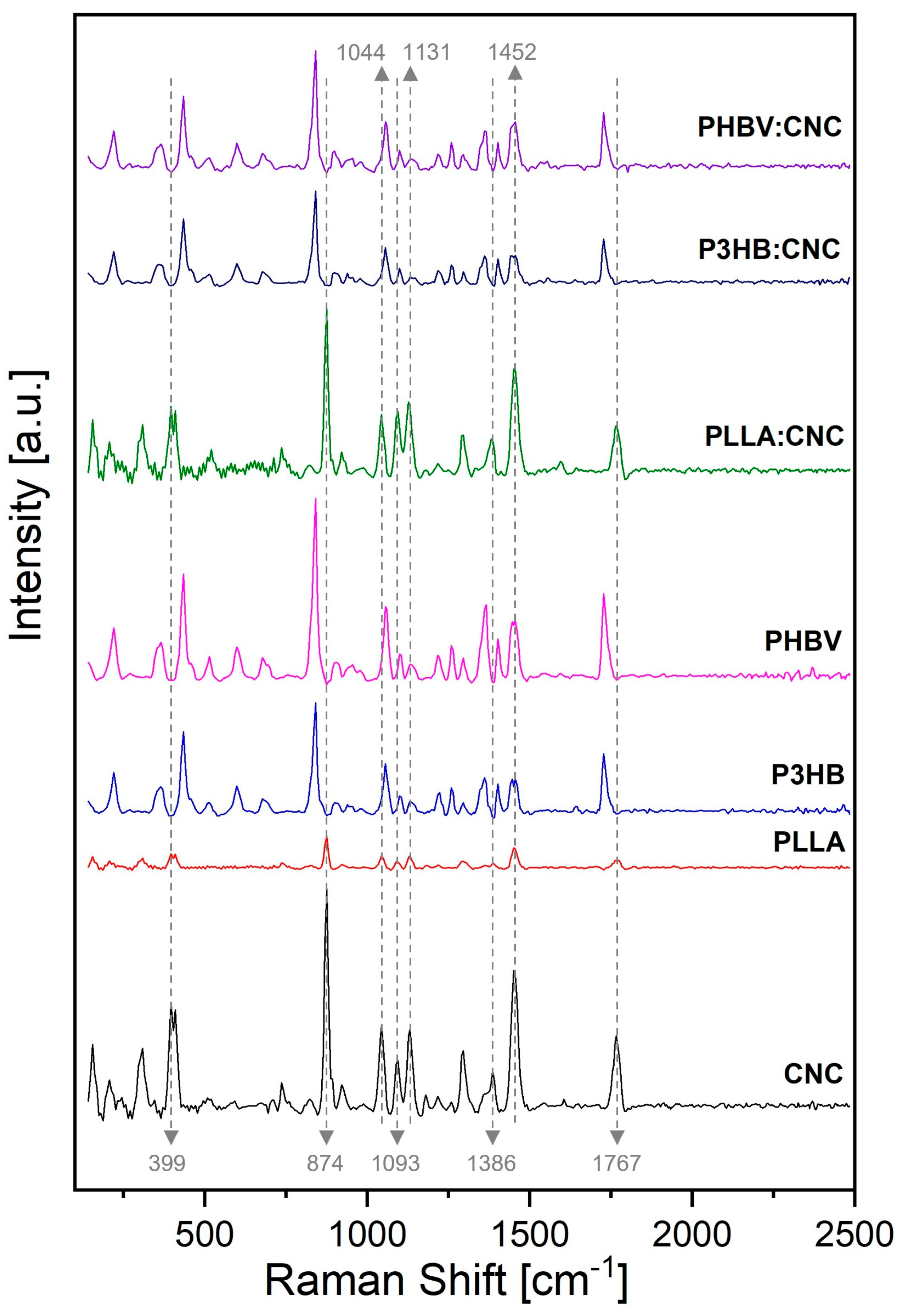
3.2.2. Raman Spectroscopy

The Raman spectra of obtained biocomposites are shown in Figure 7, and they confirm the presence of CNCs in PLLA, P3HB and PHBV-based composites by revealing the modification of the corresponding functional groups, such as β-1,4-glycosidic bond units (assigned to at 1160 cm−1 and 1101 cm−1) and glucose ring’s glycosidic linkages (assigned between 839 cm−1 and 893 cm−1), and the existence of intermolecular interactions between polymers and CNCs [68].
Raman spectroscopy is a non-destructive method that monitors the positional shifts of different bonds and can provide valuable information on the incorporation of cellulose into biocomposites and crystallinity [73]. The Raman signals attributed to CNCs are as follows: the peak at 399 cm−1 was attributed to hydroxyl groups, while the peak at 874 cm−1 was assigned to C–OH linkage and C–C and C–O stretching modes. The peak at 1093 cm−1 was associated with the C–O–C ring and β–1,4–glycosidic linkage, while the peak at 1131 cm−1 was attributed to C–O stretching absorption. The peak at 1386 cm−1 is generally attributed to H–O–H bending mode, and the peak at 1452 cm−1 corresponds to COH bending. Finally, the strong band at 1044 cm−1 is generated by the C–O groups. Furthermore, the Raman spectrum shows several characteristic peaks for amorphous cellulose. The absorption at 1767 cm−1 indicates the presence of ester carbonyl groups resulting from the successful esterification reaction of lactic acid.
Figure 7 shows the Raman spectra of PLLA and PLLA with CNCs, demonstrating the vibration shifts resulting from their interaction. The absorption band at 1766 cm–1 was attributed to C=O stretching from keto esters. The absorption at 1455 cm−1 and 1382 cm−1 was assigned to a methyl group. The bands at 1295 cm−1 and 1126 cm−1 are assigned to C–O–C from esters. The absorption at 1126 cm−1 was attributed to C–O–C stretching from PLLA. The peaks at 1044 cm−1 and 1093 cm−1 are attributed to C–O stretching vibrations. The 874 cm−1 and 746 cm−1 peaks correspond to the amorphous and crystalline phases from PLLA [74].
Furthermore, the Raman spectrum of P3HB displayed the following peaks: 1728 cm−1 was attributed to vibration of C=O group, 1360 cm−1 was assigned to methyl group, 1099 cm−1 was vibration of C–O–C, and 1056 cm−1 was assigned to C–CH3 [75]. The signals at 1403 cm−1 and 1455 cm−1 were attributed to the modification of P3HB–CNC structure by the incorporation of CNCs into the polymer matrix. The signal at 839 cm−1 was attributed to the crystalline phase formed in the P3HB:CNC composite. The absorption peaks at 1728 cm−1 in P3HB:CNC and at 1766 cm−1 in PHBV:CNC indicate the presence of ester carbonyl groups of lactic acid within the cellulose. Instead, the peak at 1728 cm−1 in the spectrum of PHBV represents the band position for the hydrogen bond and is slightly shifted from 1721 cm−1 upon the addition of CNCs. This observation is consistent with the findings reported in the literature [71]. Thus, our Raman analysis performed on all three biocomposites confirms their homogeneous composition and the incorporation of CNCs into the polymeric matrix. Moreover, it points toward the existence of hydrogen bond interactions between the CNCs and all corresponding polymers.

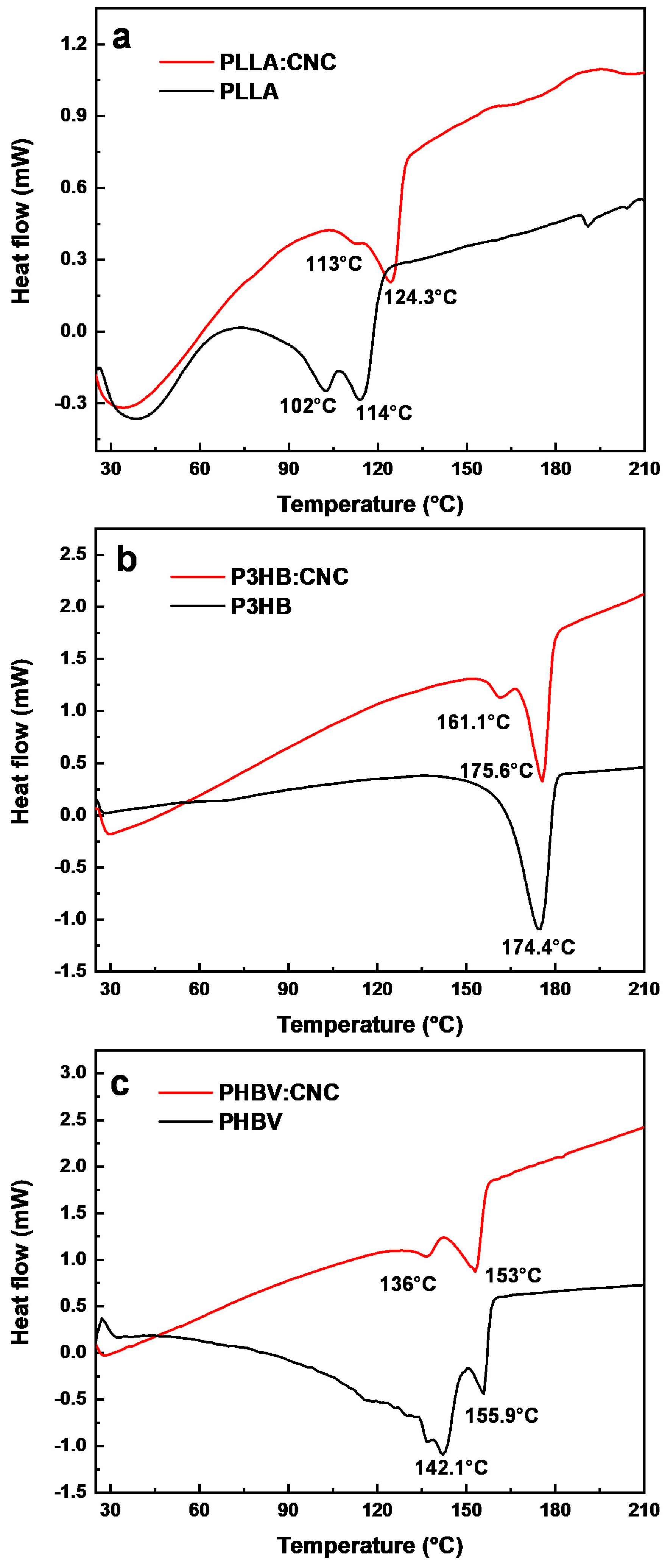
3.2.3. DSC Characterization of the Polymer/CNC Composites

Figure 8 shows the DSC curves recorded for all polymer–CNC composites. In order to understand the crystallinity of our composites, we have inferred from the data not only the temperature of crystallization (Tc) but also the melting temperature (Tm) and associated enthalpies (ΔH). The obtained results emphasized the existence of a single Tg and Tm in all analyzed samples, indicating that there was an excellent miscibility between each polymer and CNC. All enthalpies were measured directly by the DSC analyzer.
Figure 8a shows the PLLA and PLLA:CNC thermograms exhibiting all crystallization and melting endotherm temperatures. The crystallization for PLLA occurred at 102.97 °C with ΔHc of −2.69 J/g and for PLLA:CNC at 113.07 °C with ΔHc of −0.49 J/g. Moreover, the Tm was determined to be slightly over 114.15 °C with a melting enthalpy ΔHm = −8.44 J/g for PLLA and 124.28 °C with a melting enthalpy ΔHm = −10.70 J/g for PLLA:CNC, respectively.
In the case of P3HB, no crystallization peak was observed, and for P3HB:CNC (Figure 8b), Tc has peaked at 161.12 °C, with crystallization enthalpy ΔHc of −3.03 J/g. The melting temperature for P3HB was detected at 174.89 °C with ΔHm = 58.87 J/g, and for P3HB:CNC at 175.64 °C with ΔHm = 27.44 J/g. According to the literature, polymers with higher Tg have a better elastic modulus and thus resist deformation better [76]. The enthalpy of PLLA inferred from the literature is 93 J/g, while this parameter is 146.6 J/g for P3HB and 146.6 J/g for PHBV.
Moreover, the Tc for PHBV and the PHBV:CNC composite was determined to occur at 142.15 °C and 136.07 °C (Figure 8c). In these cases, the value of crystallization enthalpy ΔHc was –4.57 J/g and −3.40 J/g, respectively. Furthermore, the two measured Tm corresponding to these materials were 155.89 °C (with ΔHm = −6.75 J/g) and 152.93 °C (with ΔHm = −20.35 J/g). Finally, the degree of crystallinity calculated for PLLA:CNC, P3HB:CNC, and PHBV:CNC were 11.50%, 16.71%, and 11.60%, respectively (Table 1). The degree of crystallinity was calculated by dividing the difference between the enthalpy of melting and the enthalpy of crystallization at the enthalpy of 100% crystalline material, according to [71]. Thus, the incorporation of CNCs into polymers increased the enthalpy of crystallization.

4. Conclusions

This study demonstrated that the incorporation of cellulose nanocrystals in biocomposite films based on PLLA, P3HB or PHBV favored the formation of crystalline nanostructures, such as fractal-like, needle-like or spherulitic morphologies, that are further comprised of substructures of either lamellar/fibrillar or spherical shapes. Our experiments further revealed that these crystalline morphologies were possible to generate only when the incorporation of CNCs was accompanied by a further processing of thin film composites via the C-SVA technique.
Finally, the obtained results indicated that the inclusion of CNCs in biodegradable polymeric thin films improved their crystallinity and could provide a good alternative to novel film composites.

Author Contributions

Conceptualization, investigation, writing—original draft preparation and investigation, L.S. and O.T.-B.; conceptualization, methodology, writing—original draft; I.B.; data curation and formal analysis, C.R.; formal analysis and investigation, D.S., M.D. and I.K.; conceptualization, investigation and writing—review and editing M.S. All authors have read and agreed to the published version of the manuscript.

Funding

This work was supported by a grant of the Ministry of Research, Innovation and Digitization, CNCS-UEFISCDI, project number PN-III-P1-1.1-TE-2021-0179, within PNCDI III, LIGNOBIOPLAST. This work was carried out through the Core Program within the National Research Development and Innovation Plan 2022–2027, carried out with the support of MCID, project no. PN 23 05.

Institutional Review Board Statement

Not applicable.

Informed Consent Statement

Not applicable.

Data Availability Statement

Data are contained within the article.

Conflicts of Interest

The authors declare no conflicts of interest.

References

  1. Bhagia, S.; Bornani, K.; Agrawal, R.; Satlewal, A.; Ďurkovič, J.; Lagaňa, R.; Bhagia, M.; Yoo, C.G.; Zhao, X.; Kunc, V.; et al. Critical Review of FDM 3D Printing of PLA Biocomposites Filled with Biomass Resources, Characterization, Biodegradability, Upcycling and Opportunities for Biorefineries. Appl. Mater. Today 2021, 24, 101078. [Google Scholar] [CrossRef]
  2. Houfani, A.A.; Anders, N.; Spiess, A.C.; Baldrian, P.; Benallaoua, S. Insights from Enzymatic Degradation of Cellulose and Hemicellulose to Fermentable Sugars—A Review. Biomass Bioenergy 2020, 134, 105481. [Google Scholar] [CrossRef]
  3. Zhao, X.; Zhang, L.; Liu, D. Biomass Recalcitrance. Part I: The Chemical Compositions and Physical Structures Affecting the Enzymatic Hydrolysis of Lignocellulose. Biofuels Bioprod. Biorefin. 2012, 6, 465–482. [Google Scholar] [CrossRef]
  4. Ciolacu, D.; Rudaz, C.; Vasilescu, M.; Budtova, T. Physically and Chemically Cross-Linked Cellulose Cryogels: Structure, Properties and Application for Controlled Release. Carbohydr. Polym. 2016, 151, 392–400. [Google Scholar] [CrossRef]
  5. Gauss, C.; Pickering, K.L.; Muthe, L.P. The Use of Cellulose in Bio-Derived Formulations for 3D/4D Printing: A Review. Compos. C Open Access 2021, 4, 100113. [Google Scholar] [CrossRef]
  6. Landry, V.; Alemdar, A.; Blanchet, P. Nanocrystalline Cellulose: Morphological, Physical, and Mechanical Properties. For. Prod. J. 2011, 61, 104–112. [Google Scholar] [CrossRef]
  7. Sun, X.; Wu, Q.; Zhang, X.; Ren, S.; Lei, T.; Li, W.; Xu, G.; Zhang, Q. Nanocellulose Films with Combined Cellulose Nanofibers and Nanocrystals: Tailored Thermal, Optical and Mechanical Properties. Cellulose 2018, 25, 1103–1115. [Google Scholar] [CrossRef]
  8. Revin, V.V.; Liyaskina, E.V.; Parchaykina, M.V.; Kuzmenko, T.P.; Kurgaeva, I.V.; Revin, V.D.; Ullah, M.W. Bacterial Cellulose-Based Polymer Nanocomposites: A Review. Polymers 2022, 14, 4670. [Google Scholar] [CrossRef] [PubMed]
  9. Qua, E.H.; Hornsby, P.R.; Sharma, H.S.S.; Lyons, G. Preparation and Characterisation of Cellulose Nanofibres. J. Mater. Sci. 2011, 46, 6029–6045. [Google Scholar] [CrossRef]
  10. Mujtaba, M.; Fernandes Fraceto, L.; Fazeli, M.; Mukherjee, S.; Savassa, S.M.; Araujo De Medeiros, G.; Do Espírito Santo Pereira, A.; Mancini, S.D.; Lipponen, J.; Vilaplana, F. Lignocellulosic Biomass from Agricultural Waste to the Circular Economy: A Review with Focus on Biofuels, Biocomposites and Bioplastics. J. Clean. Prod. 2023, 402, 136815. [Google Scholar] [CrossRef]
  11. To, A.T.; Chung, P.; Katz, A. Weak-Acid Sites Catalyze the Hydrolysis of Crystalline Cellulose to Glucose in Water: Importance of Post-Synthetic Functionalization of the Carbon Surface. Angew. Chem. Int. Ed. 2015, 54, 11050–11053. [Google Scholar] [CrossRef]
  12. Pycka, S.; Roman, K. Comparison of Wood-Based Biocomposites with Polylactic Acid (PLA) Density Profiles by Desaturation and X-Ray Spectrum Methods. Materials 2023, 16, 5729. [Google Scholar] [CrossRef]
  13. Jenkins, A.D.; Kratochvíl, P.; Stepto, R.F.T.; Suter, U.W. Glossary of Basic Terms in Polymer Science (IUPAC Recommendations 1996). Pure Appl. Chem. 1996, 68, 2287–2311. [Google Scholar] [CrossRef]
  14. Allara, D.L. Aging of Polymers. Environ. Health Perspect. 1975, 11, 29–33. [Google Scholar] [CrossRef]
  15. Busico, V.; Cipullo, R. Microstructure of Polypropylene. Prog. Polym. Sci. 2001, 26, 443–533. [Google Scholar] [CrossRef]
  16. Babutan, I.; Lucaci, A.-D.; Botiz, I. Antimicrobial Polymeric Structures Assembled on Surfaces. Polymers 2021, 13, 1552. [Google Scholar] [CrossRef]
  17. Moohan, J.; Stewart, S.A.; Espinosa, E.; Rosal, A.; Rodríguez, A.; Larrañeta, E.; Donnelly, R.F.; Domínguez-Robles, J. Cellulose Nanofibers and Other Biopolymers for Biomedical Applications. A Review. Appl. Sci. 2019, 10, 65. [Google Scholar] [CrossRef]
  18. Liu, J.; Qi, P.; Chen, F.; Zhang, J.; Li, H.; Sun, J.; Gu, X.; Zhang, S. A Universal Eco-Friendly Flame Retardant Strategy for Polylactic Acid Fabrics and Other Polymer Substrates. Int. J. Biol. Macromol. 2024, 260, 129411. [Google Scholar] [CrossRef]
  19. Dimov, I.B.; Moser, M.; Malliaras, G.G.; McCulloch, I. Semiconducting Polymers for Neural Applications. Chem. Rev. 2022, 122, 4356–4396. [Google Scholar] [CrossRef]
  20. He, Y.; Kukhta, N.A.; Marks, A.; Luscombe, C.K. The Effect of Side Chain Engineering on Conjugated Polymers in Organic Electrochemical Transistors for Bioelectronic Applications. J. Mater. Chem. C 2022, 10, 2314–2332. [Google Scholar] [CrossRef]
  21. Botiz, I.; Durbin, M.M.; Stingelin, N. Providing a Window into the Phase Behavior of Semiconducting Polymers. Macromolecules 2021, 54, 5304–5320. [Google Scholar] [CrossRef]
  22. Pham, Q.-T.; Chern, C.-S. Applications of Polymers in Lithium-Ion Batteries with Enhanced Safety and Cycle Life. J. Polym. Res. 2022, 29, 124. [Google Scholar] [CrossRef]
  23. Yarali, E.; Baniasadi, M.; Zolfagharian, A.; Chavoshi, M.; Arefi, F.; Hossain, M.; Bastola, A.; Ansari, M.; Foyouzat, A.; Dabbagh, A.; et al. Magneto-/Electro-responsive Polymers toward Manufacturing, Characterization, and Biomedical/Soft Robotic Applications. Appl. Mater. Today 2022, 26, 101306. [Google Scholar] [CrossRef]
  24. Angel, N.; Li, S.; Yan, F.; Kong, L. Recent Advances in Electrospinning of Nanofibers from Bio-Based Carbohydrate Polymers and Their Applications. Trends Food Sci. 2022, 120, 308–324. [Google Scholar] [CrossRef]
  25. Handrea-Dragan, M.; Botiz, I. Multifunctional Structured Platforms: From Patterning of Polymer-Based Films to Their Subsequent Filling with Various Nanomaterials. Polymers 2021, 13, 445. [Google Scholar] [CrossRef] [PubMed]
  26. Gross, R.A.; Kalra, B. Biodegradable Polymers for the Environment. Science 2002, 297, 803–807. [Google Scholar] [CrossRef] [PubMed]
  27. Anwer, A.H.; Ahtesham, A.; Shoeb, M.; Mashkoor, F.; Ansari, M.Z.; Zhu, S.; Jeong, C. State-of-the-Art Advances in Nanocomposite and Bio-Nanocomposite Polymeric Materials: A Comprehensive Review. Adv. Colloid Interface Sci. 2023, 318, 102955. [Google Scholar] [CrossRef] [PubMed]
  28. Kumar, R.; Lalnundiki, V.; Shelare, S.D.; Abhishek, G.J.; Sharma, S.; Sharma, D.; Kumar, A.; Abbas, M. An Investigation of the Environmental Implications of Bioplastics: Recent Advancements on the Development of Environmentally Friendly Bioplastics Solutions. Environ. Res. 2024, 244, 117707. [Google Scholar] [CrossRef] [PubMed]
  29. Gavande, V.; Nagappan, S.; Seo, B.; Lee, W.-K. A Systematic Review on Green and Natural Polymeric Nanofibers for Biomedical Applications. Int. J. Biol. Macromol. 2024, 262, 130135. [Google Scholar] [CrossRef]
  30. Kolybaba, M.; Tabil, L.G.; Panigrahi, S.; Crerar, W.J.; Powell, T.; Wang, B. Biodegradable Polymers: Past, Present, and Future; American Society of Agricultural and Biological Engineers: St. Joseph, MI, USA, 2003. [Google Scholar] [CrossRef]
  31. De, S.; James, B.; Ji, J.; Wasti, S.; Zhang, S.; Kore, S.; Tekinalp, H.; Li, Y.; Ureña-Benavides, E.E.; Vaidya, U.; et al. Biomass-Derived Composites for Various Applications. In Advances in Bioenergy; Elsevier: Amsterdam, The Netherlands, 2023; Volume 8, pp. 145–196. ISBN 978-0-443-18856-5. [Google Scholar]
  32. Isikgor, F.H.; Becer, C.R. Lignocellulosic Biomass: A Sustainable Platform for the Production of Bio-Based Chemicals and Polymers. Polym. Chem. 2015, 6, 4497–4559. [Google Scholar] [CrossRef]
  33. Yeo, J.C.C.; Muiruri, J.K.; Thitsartarn, W.; Li, Z.; He, C. Recent Advances in the Development of Biodegradable PHB-Based Toughening Materials: Approaches, Advantages and Applications. Mater. Sci. Eng. C 2018, 92, 1092–1116. [Google Scholar] [CrossRef]
  34. Shanmugam, V.; Mensah, R.A.; Försth, M.; Sas, G.; Restás, Á.; Addy, C.; Xu, Q.; Jiang, L.; Neisiany, R.E.; Singha, S.; et al. Circular Economy in Biocomposite Development: State-of-the-Art, Challenges and Emerging Trends. Compos. C Open Access 2021, 5, 100138. [Google Scholar] [CrossRef]
  35. Bhat, A.R.; Kumar, R.; Mural, P.K.S. Natural Fiber Reinforced Polymer Composites: A Comprehensive Review of Tribo-Mechanical Properties. Tribol. Int. 2023, 189, 108978. [Google Scholar] [CrossRef]
  36. Bucci, D.Z.; Tavares, L.B.B.; Sell, I. PHB Packaging for the Storage of Food Products. Polym. Test. 2005, 24, 564–571. [Google Scholar] [CrossRef]
  37. Manavitehrani, I.; Fathi, A.; Badr, H.; Daly, S.; Negahi Shirazi, A.; Dehghani, F. Biomedical Applications of Biodegradable Polyesters. Polymers 2016, 8, 20. [Google Scholar] [CrossRef]
  38. Li, Z.; Loh, X.J. Recent Advances of Using Polyhydroxyalkanoate-based Nanovehicles as Therapeutic Delivery Carriers. WIREs Nanomed. Nanobiotechnol. 2017, 9, e1429. [Google Scholar] [CrossRef]
  39. El-Kadi, S.M.; Elbagory, M.; EL-Zawawy, H.A.H.; EL-Shaer, H.F.A.; Shoukry, A.A.; El-Nahrawy, S.; Omara, A.E.-D.; Ali, D.F.I. Biosynthesis of Poly-ß-Hydroxybutyrate (PHB) from Different Bacterial Strains Grown on Alternative Cheap Carbon Sources. Polymers 2021, 13, 3801. [Google Scholar] [CrossRef]
  40. Holmes, P.A. Applications of PHB—A Microbially Produced Biodegradable Thermoplastic. Phys. Technol. 1985, 16, 32–36. [Google Scholar] [CrossRef]
  41. Shishatskaya, E.I.; Khlusov, I.A.; Volova, T.G. A Hybrid PHB–Hydroxyapatite Composite for Biomedical Application: Production, in Vitro and in Vivo Investigation. J. Biomater. Sci. Polym. Ed. 2006, 17, 481–498. [Google Scholar] [CrossRef]
  42. Poltronieri, P.; Mezzolla, V.; D’Urso, O.F. PHB Production in Biofermentors Assisted through Biosensor Applications. In Proceedings of the 3rd International Electronic Conference on Sensors and Applications, Online, 15–30 November 2016; p. 4. Available online: https://sciforum.net/conference/ecsa-3 (accessed on 29 January 2024).
  43. Costa, J.A.V.; Moreira, J.B.; Lucas, B.F.; Braga, V.D.S.; Cassuriaga, A.P.A.; Morais, M.G.D. Recent Advances and Future Perspectives of PHB Production by Cyanobacteria. Ind. Biotechnol. 2018, 14, 249–256. [Google Scholar] [CrossRef]
  44. Anjana; Raturi, G.; Shree, S.; Sharma, A.; Panesar, P.S.; Goswami, S. Recent Approaches for Enhanced Production of Microbial Polyhydroxybutyrate: Preparation of Biocomposites and Applications. Int. J. Biol. Macromol. 2021, 182, 1650–1669. [Google Scholar] [CrossRef]
  45. Song, W.; Yang, Z.; Zhang, S.; Fei, B.; Zhao, R. Properties Enhancement of Poly(β-Hydroxybutyrate) Biocomposites by Incorporating Surface-Modified Wheat Straw Flour: Effect of Pretreatment Methods. Int. J. Biol. Macromol. 2023, 232, 123456. [Google Scholar] [CrossRef]
  46. Kostag, M.; El Seoud, O.A. Sustainable Biomaterials Based on Cellulose, Chitin and Chitosan Composites—A Review. Carbohydr. Polym. Technol. Appl. 2021, 2, 100079. [Google Scholar] [CrossRef]
  47. Panaitescu, D.M.; Nicolae, C.A.; Gabor, A.R.; Trusca, R. Thermal and Mechanical Properties of Poly(3-Hydroxybutyrate) Reinforced with Cellulose Fibers from Wood Waste. Ind. Crops Prod. 2020, 145, 112071. [Google Scholar] [CrossRef]
  48. Diyana, Z.N.; Jumaidin, R.; Selamat, M.Z.; Ghazali, I.; Julmohammad, N.; Huda, N.; Ilyas, R.A. Physical Properties of Thermoplastic Starch Derived from Natural Resources and Its Blends: A Review. Polymers 2021, 13, 1396. [Google Scholar] [CrossRef]
  49. Zaaba, N.F.; Ismail, H. Thermoplastic/Natural Filler Composites: A Short Review. JPS 2019, 30, 81–99. [Google Scholar] [CrossRef]
  50. Abdul Khalil, H.P.S.; Chong, E.W.N.; Owolabi, F.A.T.; Asniza, M.; Tye, Y.Y.; Rizal, S.; Nurul Fazita, M.R.; Mohamad Haafiz, M.K.; Nurmiati, Z.; Paridah, M.T. Enhancement of Basic Properties of Polysaccharide-based Composites with Organic and Inorganic Fillers: A Review. J. Appl. Polym. Sci. 2019, 136, 47251. [Google Scholar] [CrossRef]
  51. Ling, S.; Chen, W.; Fan, Y.; Zheng, K.; Jin, K.; Yu, H.; Buehler, M.J.; Kaplan, D.L. Biopolymer Nanofibrils: Structure, Modeling, Preparation, and Applications. Prog. Polym. Sci. 2018, 85, 1–56. [Google Scholar] [CrossRef]
  52. Senila, L.; Cadar, O.; Kovacs, E.; Gal, E.; Dan, M.; Stupar, Z.; Simedru, D.; Senila, M.; Roman, C. L-Poly(Lactic Acid) Production by Microwave Irradiation of Lactic Acid Obtained from Lignocellulosic Wastes. Int. J. Mol. Sci. 2023, 24, 9817. [Google Scholar] [CrossRef]
  53. Todor-Boer, O.; Petrovai, I.; Tarcan, R.; Vulpoi, A.; David, L.; Astilean, S.; Botiz, I. Enhancing Photoluminescence Quenching in Donor–Acceptor PCE11:PPCBMB Films through the Optimization of Film Microstructure. Nanomaterials 2019, 9, 1757. [Google Scholar] [CrossRef]
  54. Botiz, I. Prominent Processing Techniques to Manipulate Semiconducting Polymer Microstructures. J. Mater. Chem. C 2023, 11, 364–405. [Google Scholar] [CrossRef]
  55. Todor-Boer, O.; Petrovai, I.; Tarcan, R.; David, L.; Astilean, S.; Botiz, I. Control of Microstructure in Polymer: Fullerene Active Films by Convective Self-Assembly. Thin Solid Films 2020, 697, 137780. [Google Scholar] [CrossRef]
  56. Babutan, I.; Todor-Boer, O.; Atanase, L.I.; Vulpoi, A.; Botiz, I. Crystallization of Poly(Ethylene Oxide)-Based Triblock Copolymers in Films Swollen-Rich in Solvent Vapors. Coatings 2023, 13, 918. [Google Scholar] [CrossRef]
  57. Babutan, I.; Todor-Boer, O.; Atanase, L.I.; Vulpoi, A.; Simon, S.; Botiz, I. Self-Assembly of Block Copolymers on Surfaces Exposed to Space-Confined Solvent Vapor Annealing. Polymer 2023, 273, 125881. [Google Scholar] [CrossRef]
  58. Babutan, I.; Todor-Boer, O.; Atanase, L.I.; Vulpoi, A.; Botiz, I. Self-Assembly of Block Copolymers in Thin Films Swollen-Rich in Solvent Vapors. Polymers 2023, 15, 1900. [Google Scholar] [CrossRef]
  59. Posselt, D.; Zhang, J.; Smilgies, D.-M.; Berezkin, A.V.; Potemkin, I.I.; Papadakis, C.M. Restructuring in Block Copolymer Thin Films: In Situ GISAXS Investigations during Solvent Vapor Annealing. Prog. Polym. Sci. 2017, 66, 80–115. [Google Scholar] [CrossRef]
  60. Senila, L.; Gál, E.; Kovacs, E.; Cadar, O.; Dan, M.; Senila, M.; Roman, C. Poly(3-Hydroxybutyrate) Production from Lignocellulosic Wastes Using Bacillus Megaterium ATCC 14581. Polymers 2023, 15, 4488. [Google Scholar] [CrossRef] [PubMed]
  61. Senila, L.; Kovacs, E.; Scurtu, D.A.; Cadar, O.; Becze, A.; Senila, M.; Levei, E.A.; Dumitras, D.E.; Tenu, I.; Roman, C. Bioethanol Production from Vineyard Waste by Autohydrolysis Pretreatment and Chlorite Delignification via Simultaneous Saccharification and Fermentation. Molecules 2020, 25, 2606. [Google Scholar] [CrossRef] [PubMed]
  62. Wang, Z.; Yao, Z.; Zhou, J.; He, M.; Jiang, Q.; Li, A.; Li, S.; Liu, M.; Luo, S.; Zhang, D. Improvement of Polylactic Acid Film Properties through the Addition of Cellulose Nanocrystals Isolated from Waste Cotton Cloth. Int. J. Biol. Macromol. 2019, 129, 878–886. [Google Scholar] [CrossRef]
  63. Zhao, X.; Yu, J.; Liang, X.; Huang, Z.; Li, J.; Peng, S. Crystallization Behaviors Regulations and Mechanical Performances Enhancement Approaches of Polylactic Acid (PLA) Biodegradable Materials Modified by Organic Nucleating Agents. Int. J. Biol. Macromol. 2023, 233, 123581. [Google Scholar] [CrossRef]
  64. Arrieta, M.P.; Fortunati, E.; Dominici, F.; López, J.; Kenny, J.M. Bionanocomposite Films Based on Plasticized PLA–PHB/Cellulose Nanocrystal Blends. Carbohydr. Polym. 2015, 121, 265–275. [Google Scholar] [CrossRef] [PubMed]
  65. Murakami, R.; Sato, H.; Dybal, J.; Iwata, T.; Ozaki, Y. Formation and Stability of β-Structure in Biodegradable Ultra-High-Molecular-Weight Poly(3-Hydroxybutyrate) by Infrared, Raman, and Quantum Chemical Calculation Studies. Polymer 2007, 48, 2672–2680. [Google Scholar] [CrossRef]
  66. Briassoulis, D.; Tserotas, P.; Athanasoulia, I.-G. Alternative Optimization Routes for Improving the Performance of Poly(3-Hydroxybutyrate) (PHB) Based Plastics. J. Clean. Prod. 2021, 318, 128555. [Google Scholar] [CrossRef]
  67. Schulz, G.L.; Ludwigs, S. Controlled Crystallization of Conjugated Polymer Films from Solution and Solvent Vapor for Polymer Electronics. Adv. Funct. Mater. 2017, 27, 1603083. [Google Scholar] [CrossRef]
  68. Mukaffa, H.; Asrofi, M.; Sujito; Asnawi; Hermawan, Y.; Sumarji; Qoryah, R.D.H.; Sapuan, S.M.; Ilyas, R.A.; Atiqah, A. Effect of Alkali Treatment of Piper Betle Fiber on Tensile Properties as Biocomposite Based Polylactic Acid: Solvent Cast-Film Method. Mater. Today Proc. 2022, 48, 761–765. [Google Scholar] [CrossRef]
  69. Samrudhi, B.M.; Devadiga, D.; Ahipa, T.N. Flame-Retardant Polymer Nanocomposite Films and Coatings. In Polymer Nanocomposite Films and Coatings; Elsevier: Amsterdam, The Netherlands, 2024; pp. 259–291. ISBN 978-0-443-19139-8. [Google Scholar]
  70. Mokhena, T.; Sefadi, J.; Sadiku, E.; John, M.; Mochane, M.; Mtibe, A. Thermoplastic Processing of PLA/Cellulose Nanomaterials Composites. Polymers 2018, 10, 1363. [Google Scholar] [CrossRef] [PubMed]
  71. Abdalkarim, S.Y.H.; Yu, H.-Y.; Wang, D.; Yao, J. Electrospun Poly(3-Hydroxybutyrate-Co-3-Hydroxy-Valerate)/Cellulose Reinforced Nanofibrous Membranes with ZnO Nanocrystals for Antibacterial Wound Dressings. Cellulose 2017, 24, 2925–2938. [Google Scholar] [CrossRef]
  72. Sessini, V.; Navarro-Baena, I.; Arrieta, M.P.; Dominici, F.; López, D.; Torre, L.; Kenny, J.M.; Dubois, P.; Raquez, J.-M.; Peponi, L. Effect of the Addition of Polyester-Grafted-Cellulose Nanocrystals on the Shape Memory Properties of Biodegradable PLA/PCL Nanocomposites. Polym. Degrad. Stab. 2018, 152, 126–138. [Google Scholar] [CrossRef]
  73. Morgan, J.J.; Craciun, M.F.; Eichhorn, S.J. Quantification of Stress Transfer in a Model Cellulose Nanocrystal/Graphene Bilayer Using Raman Spectroscopy. Compos. Sci. Technol. 2019, 177, 34–40. [Google Scholar] [CrossRef]
  74. Lizundia, E.; Fortunati, E.; Dominici, F.; Vilas, J.L.; León, L.M.; Armentano, I.; Torre, L.; Kenny, J.M. PLLA-Grafted Cellulose Nanocrystals: Role of the CNC Content and Grafting on the PLA Bionanocomposite Film Properties. Carbohydr. Polym. 2016, 142, 105–113. [Google Scholar] [CrossRef]
  75. Rincon-Granados, K.L.; Vázquez-Olmos, A.R.; Rodríguez-Hernández, A.-P.; Prado-Prone, G.; Garibay-Febles, V.; Almanza-Arjona, Y.C.; Sato-Berrú, R.Y.; Mata-Zamora, E.; Silva-Bermúdez, P.S.; Vega-Jiménez, A. Bactericidal and Cytotoxic Study of Hybrid Films Based on NiO and NiFe2O4 Nanoparticles in Poly-3-Hydroxybutyrate. J. Clust. Sci. 2024, 35, 167–178. [Google Scholar] [CrossRef]
  76. Cao, X.; Mohamed, A.; Gordon, S.H.; Willett, J.L.; Sessa, D.J. DSC Study of Biodegradable Poly(Lactic Acid) and Poly(Hydroxy Ester Ether) Blends. Thermochim. Acta 2003, 406, 115–127. [Google Scholar] [CrossRef]
Figure 1. Molecular structure of PLLA (a), P3HB (b), and PHBV (c).
Materials 17 01685 g001
Figure 2. Schematic representation of the C-SVA tool used in this work.
Materials 17 01685 g002
Figure 3. AFM height (a,b,e,f) and phase (i,j,m,n,q,r) micrographs depicting the morphology observed on the surface of PLLA:CNC thin film after (a,e,i,m,q) and before (b,f,j,n,r) C-SVA processing. AFM height (c,d,g,h) and phase (k,l,o,p,s,t) micrographs depicting the morphology observed on the surface of neat PLLA thin film after (c,g,k,o,s) and before (d,h,i,p,t) C-SVA processing. Yellow arrows are for guiding the eye only.
Materials 17 01685 g003
Figure 4. AFM height (a,b,e,f,i,j) and phase (m,n,q,r) micrographs depicting the morphology observed on the surface of P3HB:CNC thin film after (a,e,i,m,q) and before (b,f,j,n,r) C-SVA processing. AFM height (c,d,g,h,k,l) and phase (o,p,s,t) micrographs depicting the morphology observed on the surface of neat P3HB thin film after (c,g,k,o,s) and before (d,h,i,p,t) C-SVA processing. Yellow arrows are for guiding the eye only.
Materials 17 01685 g004
Figure 5. AFM height (a,b,e,f) and phase (i,j,m,n,q,r) micrographs depicting the morphology observed on the surface of PHBV:CNC thin film after (a,e,i,m,q) and before (b,f,j,n,r) C-SVA processing. AFM height (c,d,g,h) and phase (k,l,o,p,s,t) micrographs depicting the morphology observed on the surface of neat PHBV thin film after (c,g,k,o,s) and before (d,h,i,p,t) C-SVA processing. Yellow arrows are for guiding the eye only.
Materials 17 01685 g005
Figure 6. TGA and DTG plots for the (a) PLLA and PLLA:CNC, (b) P3HB and P3HB:CNC, (c) PHBV and PHBV:CNC.
Materials 17 01685 g006
Figure 7. Full Raman spectra of the CNCs, PLLA, PLLA:CNC, P3HB, P3HB:CNC, PHBV, and PHBV:CNC.
Materials 17 01685 g007
Figure 8. DSC curves recorded for (a) PLLA and PLLA:CNC, (b) P3HB and P3HB:CNC, (c) PHBV and PHBV:CNC.
Materials 17 01685 g008
Table 1. Thermal properties of neat and blended polymers.
MaterialTc (°C)Tm (°C)ΔHc (J/g)ΔHm (J/g)
PLLA102.92114.15−2.69−8.44
PLLA:CNC113.07124.28−0.49−10.7
P3HB-174.89-−58.89
P3HB:CNC161.12175.64−3.03−27.44
PHBV142.15155.89−4.57−6.75
PHBV:CNC136153−3.40−20.35
Disclaimer/Publisher’s Note: The statements, opinions and data contained in all publications are solely those of the individual author(s) and contributor(s) and not of MDPI and/or the editor(s). MDPI and/or the editor(s) disclaim responsibility for any injury to people or property resulting from any ideas, methods, instructions or products referred to in the content.

