1. Introduction
Spectral imaging systems based on an Acousto-Optic Tunable Filter (AOTF) possess numerous advantages, including rapid wavelength switching, frame-capture imaging, complete electronic control, and all-solid-state components [
1,
2]. These systems are capable of acquiring the spatial, radiometric, and spectral information of objects, and have been widely studied in space exploration [
3,
4,
5], hyper-spectral imaging [
6], and stereoscopic imaging [
7]. The AOTF is a spectral dispersive device that operates based on the elasto-optical effect, which refers to the periodic modulation of the refractive index caused by acoustic waves traveling through an optically transparent medium [
8]. The incident light waves of specific wavelengths propagating through the medium are diffracted to a certain direction. Thus, AOTF can separate the energies of different light wavelengths from the incident light by switching the frequency of the driving radio-frequency (RF) electrical signal. AOTF comes in various layout structures, which can be categorized according to the direction of the acoustic waves in relation to the incident light waves as collinear, non-collinear, and quasi-collinear types. Compared with collinear AOTFs, the diffracted and transmitted light in non-collinear AOTFs naturally separates in space, which is beneficial for spectral imaging systems that utilize diffracted light [
9]. Spectral imaging systems require a high ability to collect energy in order to enhance signal quality. As one of the core components of the spectral imaging system, the AOTF directly affects many critical performances of the spectral imaging system, such as the spectral resolution, field of view, and sensitivity. Among these, the optical throughput of the AOTF is the main limiting factor of the system’s energy-collecting ability and signal quality, especially in the infrared band. The optical throughput of the AOTF device is directly determined by characteristics such as spectral resolution, the angular aperture, and the product of transmission and diffraction efficiency.
The angular aperture of the non-collinear AOTFs developed in the early stages was very small (about 1 mrad) [
10]. Chang introduced the Parallel Tangent Principle (PTP) to achieve a wide angular aperture [
10]. The theoretical formula for the non-collinear AOTF proposed by Chang laid the foundation for AOTF and system design, which is applicable across various spectrums ranging from visible [
11] to long-wave infrared [
12], from conventional acousto-optic (AO) crystals [
13] to new types of AO crystals [
14], and from single-channel [
15] to multi-channel types [
16]. In addition, quasi-collinear devices are also a hot topic of recent research, with the advantage of achieving ultra-high spectral resolution and diffraction efficiency through very long acousto-optic interaction lengths [
17].
The types of medium used for acousto-optic interactions are quite diverse [
18]. Typically, the optically transparent medium used for the interaction between acoustic waves and optical waves in AOTF devices discussed in this paper is an anisotropic AO crystal, and the performance of the AO crystal is crucial to the device’s characteristics. Currently, the commercially mature AO crystal is tellurium dioxide (TeO
2), which has high transmittance in the 0.35 μm–5 μm range and excellent acousto-optic properties [
19]. However, the AOTF field is still actively seeking better-performing crystals, especially those that can transmit in the mid- to long-wave infrared spectrum. The mercurous bromide (Hg
2Br
2) crystal proved to be outstanding at producing broadband spectral devices due to its advantages of a broad transparent range with high transmittance from visible to long-wave infrared bands (0.42–30 μm) [
20]; high acousto-optic figure of merit of 2600 (×1.5 × 10
−18 s
3/g), which characterizes the diffraction efficiency of acousto-optic devices, while the commonly used TeO
2 has an acousto-optic figure of merit of 800 (×1.5 × 10
−18 s
3/g) [
21,
22]; and large birefringence, which characterizes the angular aperture of acousto-optic devices [
23,
24]. The challenge in Hg
2Br
2 crystal AOTF research is the availability of high-quality AOTF, resulting from difficulties in the growth of high-quality, large-size crystals and the instabilities in the bonding of piezoelectric transducers. Currently, promising preliminary results have been achieved by Hg
2Br
2 crystal devices for long-wave infrared imaging [
25]. Nevertheless, since the characteristics of the Hg
2Br
2 crystal are different from those of TeO
2, which may lead to different design methods being used for the development of TeO
2 crystal AOTFs, it is essential to research the design of Hg
2Br
2-based AOTFs for various application requirements.
This study theoretically investigated the design of non-collinear AOTF and fabricated a prototype with Hg2Br2 crystal. The phase-matching geometries and energy decline caused by phase mismatches were explored. The impact of the AO crystal’s cut parameters and the dimensions of the piezoelectric transducers on the device’s driving frequency, monochromatic angular aperture, and spectral bandwidth were analyzed, providing guidance for the design of AOTF devices with mercurous bromide crystals.
2. Methods
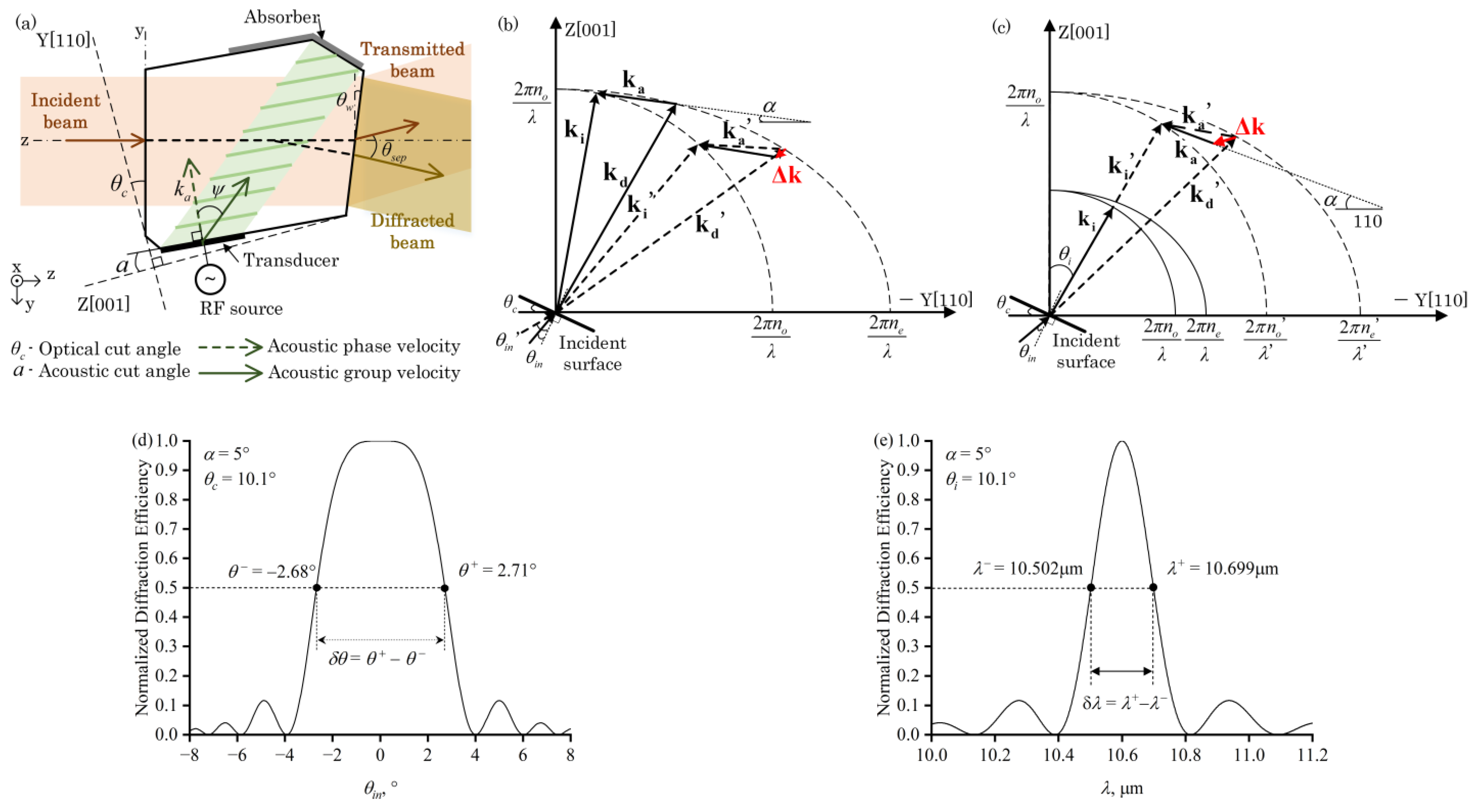
The AOTF operates based on the principle of anisotropic Bragg acousto-optic interaction. As shown in
Figure 1a, the incident light illuminates the incident surface of the AO crystal. After the refraction on the incident surface, the acousto-optic interaction occurs within the AO crystal when the incident light satisfies the phase-matching condition with the acoustic wave, filtering out diffracted light of a specific central optical wavelength. Subsequently, the diffracted light and non-diffracted light separately undergo refraction at the exit surface. The acousto-optic interaction process is represented with wave vectors, as shown by the solid lines in
Figure 1b,c, when the acoustic wave vector is
ka and the wave vectors of the incident and diffracted light,
ki and
kd, form a closed triangle, the phase matching condition is met, which is represented as follows:
The direction of the incident light wave vector
ki is normal to the incident wave, with a magnitude of
ki = 2π
ni/
λ. The diffracted light wave vector
kd is in the direction normal to the diffracted wave, with a magnitude of
kd = 2π
nd/
λ, where
λ is the wavelength of the light wave, and
ni and
nd are the optical refractive indices of the incident and diffracted light, respectively. The acoustic wave vector
ka forms an angle α with the [001] crystal axis, with a magnitude of
ka = 2π
fa/
va, where
fa is the frequency of the acoustic wave, which is also the frequency of the RF electrical signal’s input to the piezoelectric transducer and
va is the velocity of the acoustic wave. In AO crystals, the refractive index is determined by the polarization and the direction of the optical wave. The polarization of the incident light and the diffracted light in AO crystals are orthogonal to each other. The light with ordinary polarization is represented as (o). The light with extraordinary polarization is represented as (e). When the incident light is (o), the diffracted light is (e). Therefore,
ni and
nd are the refractive indices for (o) and (e), respectively. Due to the anisotropy of uniaxial crystals, the extraordinary refractive index varies with the angle
θi between the light wave and the [001] crystal axis, whereas the ordinary refractive index remains constant. The refractive indices are represented as follows [
22]:
Here,
no and
ne are the principal refractive indices of the AO crystal. The crystal is also anisotropic to acoustic waves, so the velocity of the acoustic wave varies with the direction of the acoustic wave vector, which is determined by the acoustic cut angle
α, given by [
22]:
where V
110 and V
001 are the velocities of the shear slow wave along the [110] and [001] crystal axis. Moreover, there is a deviation between the direction of the acoustic wave vector and the direction of the acoustic group velocity, as shown in
Figure 1a. The walk off angle
ψ between the group velocity and phase velocity of the acoustic wave is related to the acoustic angle
α, as follows:
The direction of the optical incidence and acoustic wave in the AOTF device is primarily controlled by two facet cuts of the AO crystal (
Figure 1a). One is the optical cut angle
θc between the incident surface of the AO crystal and the [110] crystal axis, which is represented as the Y axis in the crystal coordinate system. The other is the acoustic cut angle
α between the transducer facet of the AO crystal and the [001] crystal axis, which is represented as the Z axis in the crystal coordinate system. Additionally, the external separation angle
θsep, which is the angle between the transmitted and diffracted light in air, is related to the wedge angle
θw of the exit surface. The
θw is also fine-tuned to compensate for the chromatic aberration of the diffracted light [
24], or adjusted according to the design requirements of multiplex polarization designs [
26].
When an AOTF device operates in a practical spectral imaging system, it always lets the principal ray of the on-axis image point satisfy the phase-matching condition with the acoustic waves. Phase mismatch occurs for other forms of light due to a deviation in the incident angle, leading to a reduction in diffraction efficiency, as shown in
Figure 1b. The angular aperture is defined as the incident angle deviation corresponding to half of the peak efficiency (
Figure 1d). Therefore, the angular aperture is one of the crucial factors limiting the optical throughput that the AOTF-based spectral imaging system can receive. In addition to the diffraction efficiency reduction caused by phase-matching, another factor limiting the angular aperture of AOTF-based spectral imaging system is the separation angle between diffracted and transmitted light. The smaller value obtained due to the two factors should be chosen for the angular aperture [
27]. Thus, designing an AOTF device with a large angular aperture and wide separation angle is the foundation for achieving high-throughput spectral imaging.
The spectral bandwidth of the diffracted light is caused by the phase mismatch due to wavelength deviation, as shown in
Figure 1c. For certain applications requiring high spectral resolution, for instance, harmful gas detection [
14], the design of the AOTF device should minimize the spectral bandwidth. However, for the optical high-throughput purpose, we need to find a reasonable tradeoff between the spectral resolution and optical throughput.
The wave vector mismatch
Δk is introduced to represent the phase mismatch in the acousto-optic interaction, as follows:
Here, the wave vector mismatch
Δk is directed perpendicularly to the group velocity of the acoustic wave [
11]. The decrease in the diffraction efficiency caused by the phase mismatch can be represented as follows:
Here, LAO is the acousto-optic interaction length, which is proportional to the length of the piezoelectric transducer, L. u, which is represented as u = [πLAO(M2p/2)1/2]/λ, is a coupling coefficient related to the acousto-optic figure of merit of the AO crystal, M2, the ultrasonic power density, p, and the length of the piezoelectric transducer.
When the external incident angles,
θ+ and
θ−, cause the value of Δ
kLAO/2 to satisfy the condition that reduces
η to half of
ηp, the monochromatic angular aperture is calculated as δ
θ =
θ+ −
θ− (
Figure 1d). When the increased and decreased wavelengths, λ
+ and λ
−, cause the value of Δ
kLAO/2 to satisfy the condition that reduces the diffraction efficiency
η to half of its peak value,
ηp, the spectral bandwidth can be calculated through
δλ =
λ+ −
λ− as the full width at half of the maximum (FWHM), as shown in
Figure 1e.
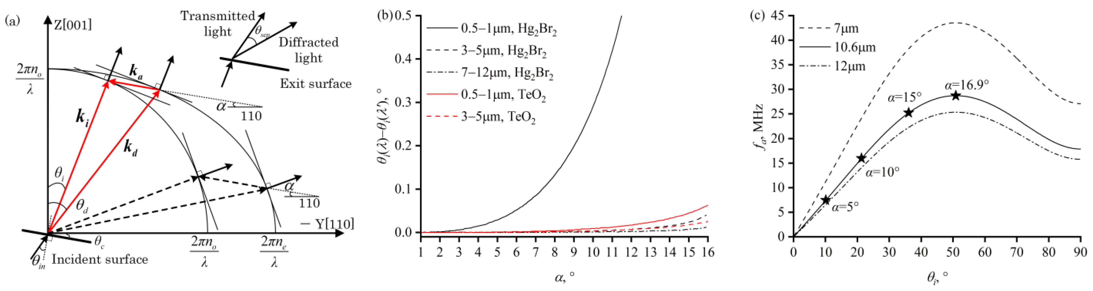
In the design of the AOTF-based spectral imaging system, it is common to make the optical cut angle and the acoustic cut angle of the AO crystal follow the PTP [
16,
28]. This principle stipulates that the tangent of the incident wave vector spherical or ellipsoidal surface at the endpoint of the incident wave vector
ki is parallel to the tangent at the endpoint of the diffracted wave vector
kd (
Figure 2a).
When this condition is met, the influence of changes in the angle of light incidence on acousto-optic diffraction is minimized, manifesting as follows. (1) The diffraction efficiency of monochromatic light varies minimally with the incident angle, θi, represented by dη/dθi = 0. Therefore, cutting the incident surface and the transducer surface of the AO crystal according to the PTP can enable the device to obtain a larger angular aperture for monochromatic light. (2) When achromatic light is incident while the acoustic wave vector’s frequency and direction remain constant, and the PTP is satisfied, the central wavelength of the diffracted light changes minimally with the incident angle, θi, denoted as dλ/dθi = 0. Hence, the central wavelength drift of an AOTF that meets the PTP condition is small, which is advantageous for specific imaging optical systems. Additionally, when the PTP is satisfied, the required driving ultrasonic frequency is relatively low.
The PTP forms a constraint between the incident angle,
θi, and the acoustic angle,
α. For a specific acoustic angle and a specific light wavelength, only one or two phase-matching combinations satisfy PTP, as shown in
Figure 2a. Since the separation angle of the phase-matching combination with a larger incident angle (dashed line) is smaller [
29], and an incidence angle close to 90° would complicate the manufacturing of the device, the smaller incident angle and its corresponding acoustic angle (solid line) are selected as the optical cut angle for the incident surface and the acoustic cut angle for the transducer surface of the AO crystal.
When the acoustic angle
α is fixed, the incident angle,
θi, that satisfies the PTP changes with wavelength. Hence, for devices with a wide operating wavelength range, the light normally entering the incident surface satisfies the PTP only for a specific wavelength. As shown in
Figure 2b, compared to the medium- and long-wave infrared bands, the PTP incident angle is more sensitive to wavelength variations in the visible to near-infrared short-wave spectral bands. Taking an acoustic angle of 5° as an example, the variation of PTP incident angle for Hg
2Br
2 crystal in the 0.5–1 μm wavelength range is 0.029°, while, in the 3–5 μm wavelength range, the variation in the PTP incident angle is 0.001°. In the short-wave band, the PTP incident angle of the Hg
2Br
2 crystal is more sensitive to wavelength variations than that of TeO
2. For instance, with an acoustic angle of 5°, the variation in the PTP incident angle for TeO
2 crystal in the 0.5–1 μm wavelength range is 0.001°, which is much less than that of Hg
2Br
2 crystal. As the acoustic angle increases, the PTP incident angle becomes more sensitive to wavelength variations. In the 0.5–1 μm wavelength range, the variation in the PTP incident angle for Hg
2Br
2 crystal at an acoustic angle of 5° is 0.029°, and at an acoustic angle of 10°, it is 0.291°; in the 7–12 μm wavelength range, the variation in the PTP incident angle for Hg
2Br
2 crystal at an acoustic angle of 10° is 0.001°, and at an acoustic angle of 15°, it is 0.007°.
Based on the phase-matching geometry, a correspondence between the driving frequency and the central wavelength of the diffracted light can be derived, which is known as the tuning curve [
30], as follows:
The required drive frequency for diffraction is inversely proportional to the diffracted light wavelength and is related to the acoustic angle. When the incident angle,
θi, and the acoustic angle,
α, satisfy the PTP, the phase-matching acoustic frequency required for the long-wave infrared wavelength range in the Hg
2Br
2 crystal is shown in
Figure 2c. The dashed and dot-dashed lines represent the acoustic frequencies corresponding to light wavelengths of 7 μm and 12 μm, respectively. Since the acoustic frequency decreases monotonically with the increase in light wavelength, the dashed and dot-dashed lines represent the upper and lower limits of the driving frequencies required for the long-wave infrared band, respectively. The stars and the corresponding tags indicate the acoustic angles that satisfy the PTP for the incident angle. The greater the acoustic angle, the higher the required driving frequency for the same wavelength, and the broader the frequency band range required for the transducer within the same working wavelength range.
3. Results and Discussion
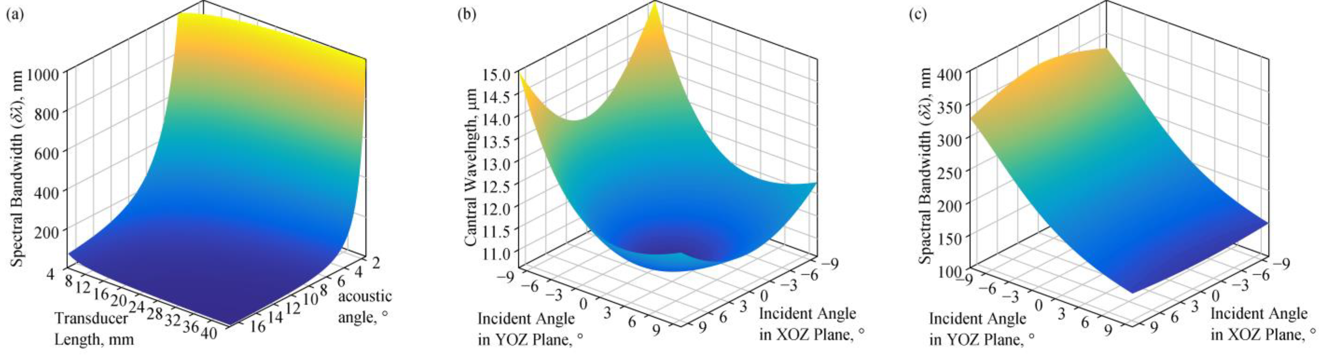
The spectral bandwidth, δλ, is related to the acousto-optic interaction length, LAO. The LAO is primarily determined by the length of the piezoelectric transducer’s top electrode, L. As the light wavelength increases, the spectral bandwidth δλ becomes wider; as the acoustic angle α increases, the δλ narrows; as the length of the AOTF’s piezoelectric transducer top electrode L increases, the δλ narrows.
The spectral bandwidth of the diffracted light is calculated at a central wavelength of 10.6 μm under different combinations of AOTF design parameters, where the incident angle and the acoustic angle satisfy the PTP. The acoustic angle, α, has a significant impact on the spectral bandwidth, δλ. With L = 15 mm, to achieve a spectral bandwidth of less than 100 nm, the acoustic angle needs to satisfy α < 6.8°. When L = 10 mm, it is only necessary for the acoustic angle to satisfy α < 8.2° to obtain a spectral bandwidth of less than 100 nm.
For the fixed acoustic angle and frequency, diffracted lights have different central wavelengths, caused by polychromatic light entering from various directions [
31], and there are also differences in the spectral bandwidth of the diffracted light. As shown in
Figure 3b,c, when the acoustic angle is 5° and the optical cut angle meets the PTP at 10.1°, the incident light entering the AOTF normally is diffracted in a central wavelength of 10.6 μm. When the external incident angle in the YOZ plane is −5°, the central wavelength of the diffracted light is 11.08 μm, and the spectral bandwidth is 1.3 times that of the normal incidence; when the external incident angle in the YOZ plane is 5°, the central wavelength is 10.87 μm, and the spectral bandwidth is 0.8 times that of the normal incidence. On the XOZ plane, when incident at an angle of 5° or −5°, the central wavelength of the diffracted light is 10.96 μm. Variations in the central wavelength and spectral bandwidth primarily occur in the YOZ plane.
For spectral imaging applications requiring high spectral finesse, it is necessary to increase the L and α. However, acoustic waves with larger acoustic angles have higher acoustic velocities within the AO crystal, leading to a decrease in the acousto-optic figure of merit, and consequently reducing the device’s diffraction efficiency. Therefore, for AOTFs that are used in imaging systems operating in high-intensity light conditions, a simultaneous increase in the acoustic angle and transducer length can be used in the AOTF design. For AOTFs that require a better diffraction efficiency and high throughput, a smaller α is often chosen, and L is enlarged as much as possible.
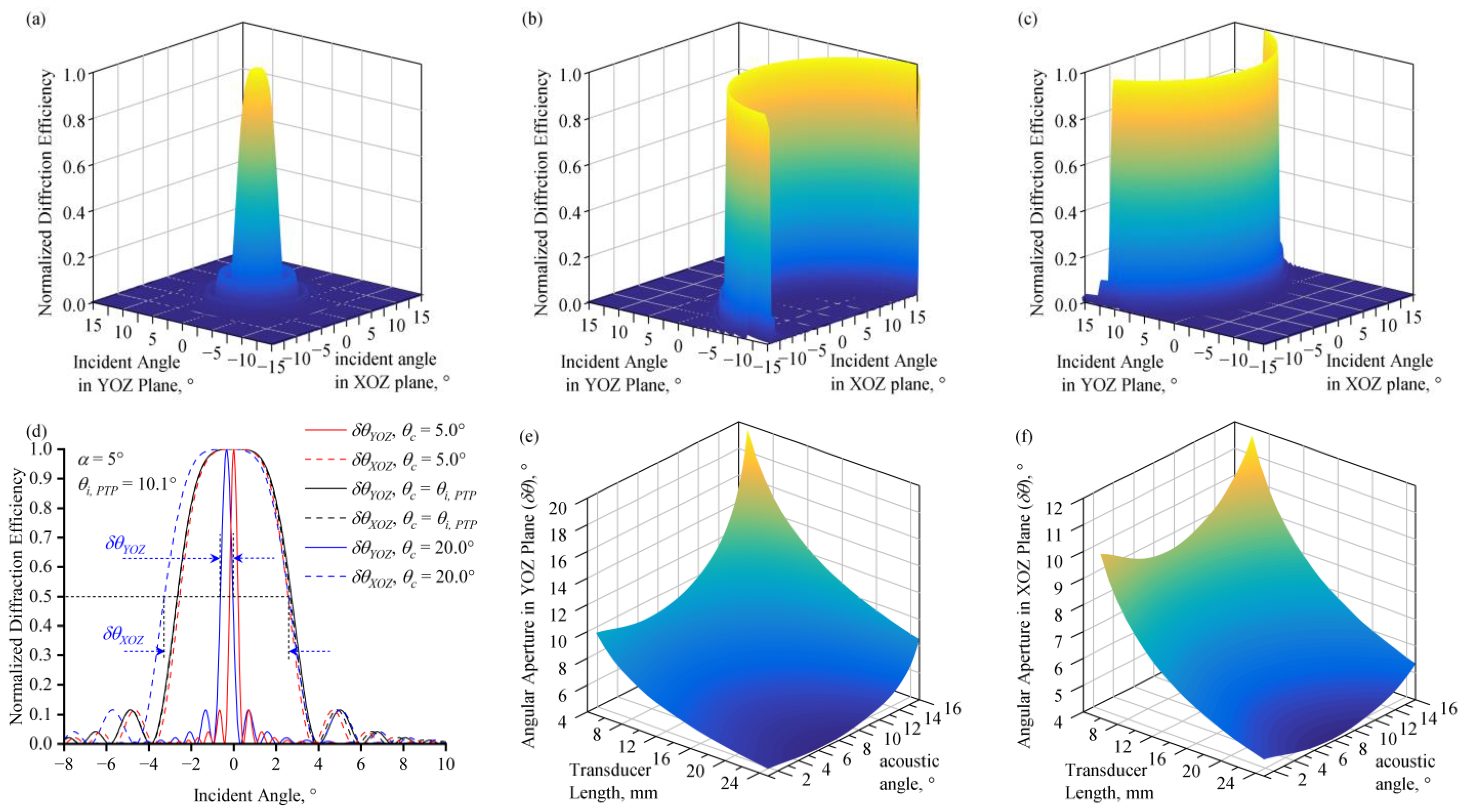
The normalized diffraction efficiency at different incident angles of monochromatic light was calculated. When the optical cut angle,
θc, and the acoustic angle,
α, satisfy the PTP, the light which is normally incident on the AOTF’s incident surface has an in-crystal incident angle that satisfies d
η/d
θi = 0. Therefore, the normalized diffraction efficiency decreases from the peak at a slow rate with the external incident angle (
Figure 4a). Consequently, AOTFs whose configuration satisfies the PTP obtain a larger monochromatic angular aperture. With an acoustic angle of 5° and a corresponding PTP incident angle of 10.1° at 10.6 μm, the black lines in
Figure 4d represent the normalized diffraction efficiency of monochromatic light with variations in the external incident angles in the XOZ and YOZ planes. Two curves are close to overlapping. Large monochromatic angular apertures of δ
θ = 5.4° are obtained in both planes.
When
θc and
α do not satisfy the PTP, a large monochromatic angular aperture is not obtained, and the response distribution of monochromatic incident light at different angles exhibits various types [
1]. For instance, when the acoustic angle is 5° and the optical cut angles are 5° and 20° respectively, the normalized diffraction efficiency across the entire field of view, as shown in
Figure 4b,c, presents a non-rotationally symmetric form. The angular aperture in the YOZ plane, δ
θYOZ, significantly decreased to less than 1°.
The monochromatic angular apertures satisfying the PTP in two planes under different design parameters were calculated, as shown in
Figure 4e,f. Both δ
θYOZ and δ
θXOZ decrease with the increase in transducer length. Both δ
θYOZ and δ
θXOZ first decrease slowly and then increase when
α increases. When
L = 15 mm, δ
θXOZ reaches its minimum at
α = 7.5°, and δ
θYOZ at
α = 6.25°, with both angular apertures having a minimum value of about 5.4°.
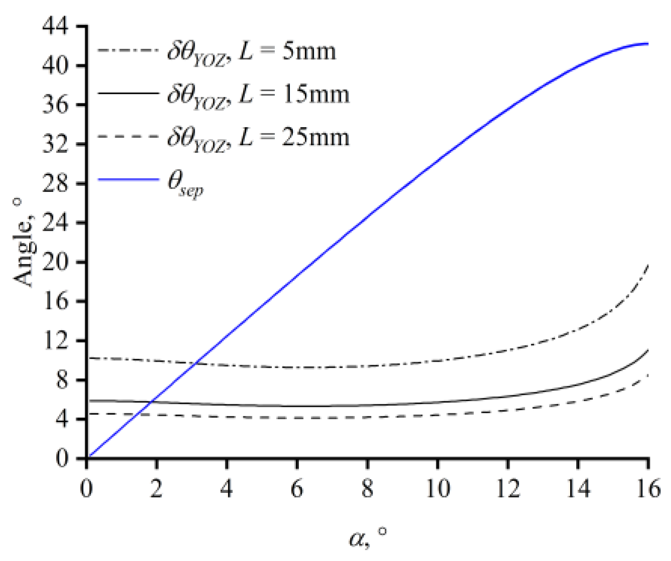
To ensure that the transmitted light does not overlap with the diffracted light, the aperture angle of the AOTF on the YOZ plane should not exceed the separation angle. For Hg
2Br
2 crystals, the separation angle monotonically increases with the acoustic angle (
Figure 5) and exceeds the monochromatic angular aperture for transducer lengths of 15 mm and 5 mm at acoustic angles of 1.9° and 3.2°, respectively.
The optical throughput of the AOTF can be estimated based on the device’s angular aperture, spectral bandwidth, and diffraction efficiency. The transmission function
Φ is shown below.
Here, λ0 and δλ are the central wavelength and the spectral bandwidth of the waveband. θX and θY are the angular apertures of the AOTF in the XOZ and YOZ planes, respectively. l is a vector composed of the cosine of the direction of the incident light. Increasing the angular aperture and spectral bandwidth is beneficial for enhancing the optical throughput of the AOTF, thereby improving the light-gathering capability of the spectral imaging system. To increase the angular aperture, it is necessary to increase the acoustic angle or decrease the transducer length. To widen the spectral bandwidth and improve the diffraction efficiency, it is necessary to decrease the acoustic angle or increase the length of the transducer. By controlling the incident cut angle and the acoustic cut angle, a wide spectral bandwidth and large angular aperture can be achieved, endowing the device with the advantage of high throughput. However, this also leads to the drawback of a reduced spectral resolution. Moreover, a larger angular aperture also implies greater optical aberrations.
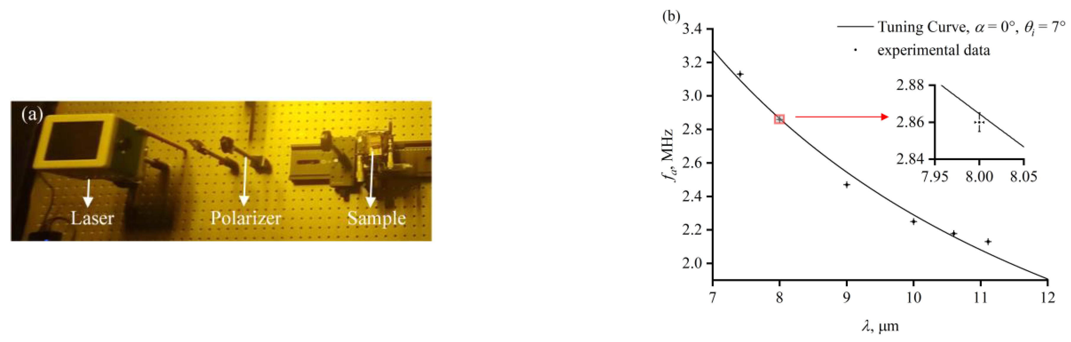
An Hg
2Br
2-based AOTF sample was prepared to verify its diffraction capability in the long-wave infrared band. In the AO crystal of the sample, the acoustic angle is 0°, at which point the relationship between the incident angle of the optical wave and the phase-matching drive frequency is close to linear, which can facilitate experimental adjustments based on the relationship between the drive frequency, the angle of the light, and the light wavelength. The incident angle of the optical wave in the AO crystal is 7°. A long-wave infrared laser (Block Engineering, Southborough, MA, USA) was used as a light source in the experiment, as shown in
Figure 6a. Laser beams with different wavelengths illuminated the incident surface of the AOTF. The frequency of the RF signal loaded on the piezoelectric transducer was adjusted until the diffracted light intensity measured by a power meter (Thorlabs, Newton, NJ, USA) was at its highest. The drive frequency was recorded with each wavelength of the laser beam. During the experiment, the experimental environment was room temperature. After the activation of the laser and the sample’s power supply, a few minutes of warm-up were needed to ensure that the laser power, the AOTF sample’s supply power, and the AO crystal’s temperature all remained stable. Then, the drive frequency was changed in increments of 0.01 MHz after recording the optical power. The measurement was repeated several times at each wavelength, and the measured values of the drive frequency corresponding to the peak diffraction showed good repeatability. The theoretical tuning curve of the sample and the measured data are shown in
Figure 6.
In recent years, studies have been carried out on the spectral bandwidth and the Hg
2Br
2 AOTF. The variations in spectral bandwidth with light wavelength, incident angle, and acoustic angle were analyzed and experimentally verified in the YOZ plane, where the incident angle in the XOZ plane is zero [
28]. A frequency bandwidth caused by phase mismatch has also been observed in the YOZ plane [
32]. The concept of increasing the separation angle to enlarge the angular aperture of the AOTF to increase optical throughput was proposed [
33]. An Hg
2Br
2 crystal device was constructed and its long-wave infrared diffraction ability was verified [
25]. Compared to these studies, this paper calculates the spectral bandwidth of diffracted light in three-dimensional space, where the angle in the XOZ plane could be non-zero. To enhance the optical throughput of spectral imaging systems, improvements in the AOTF’s angular aperture and spectral bandwidth are considered. Thus, this study analyzes how AOTF performance parameters that affect optical throughput are influenced by design parameters.


