
Effects of Pressure Rollers with Variable Compliance in the Microfinishing Process Utilizing Abrasive Films

 ,
,  ,
, 
 and
and 
Abstract
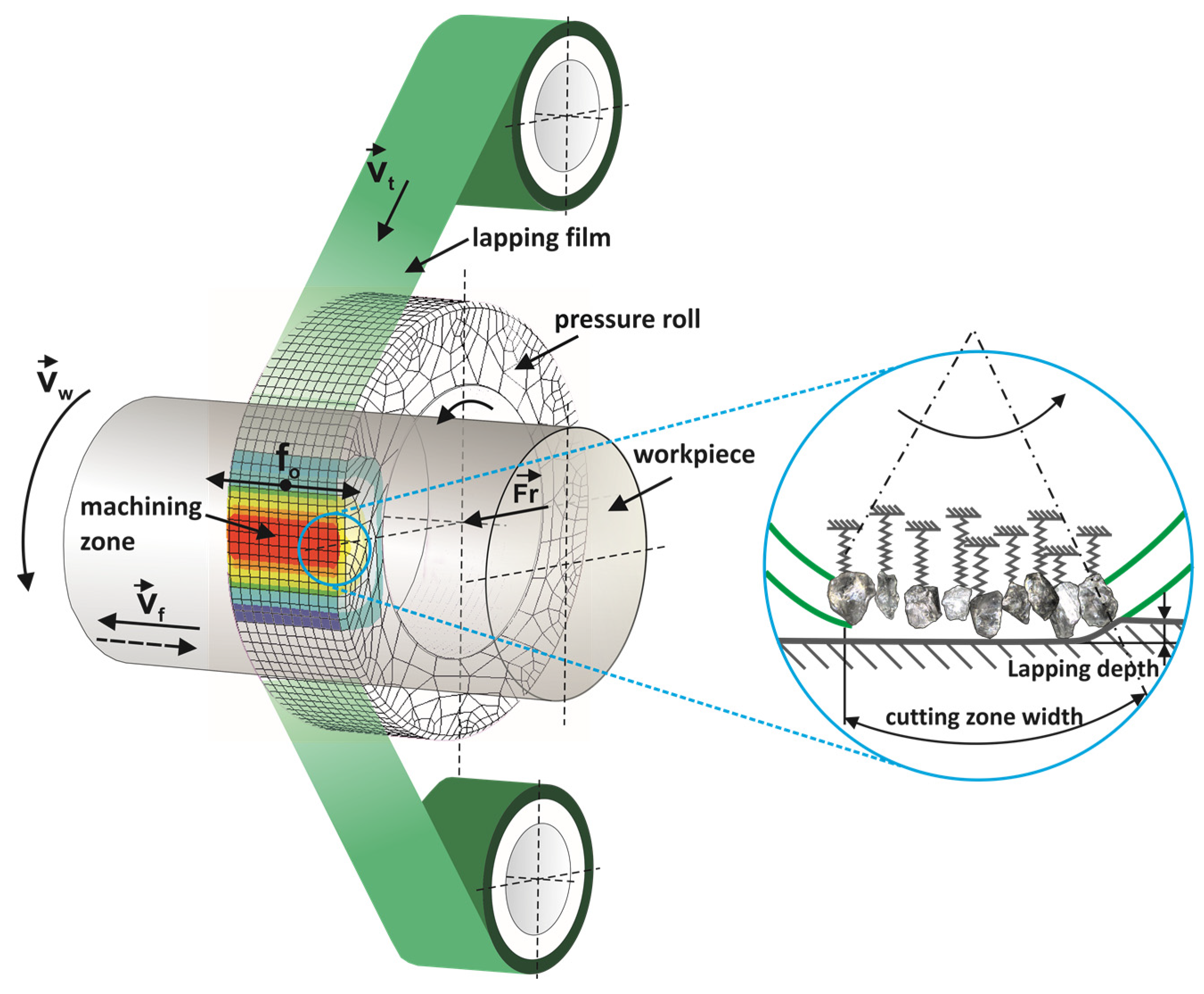
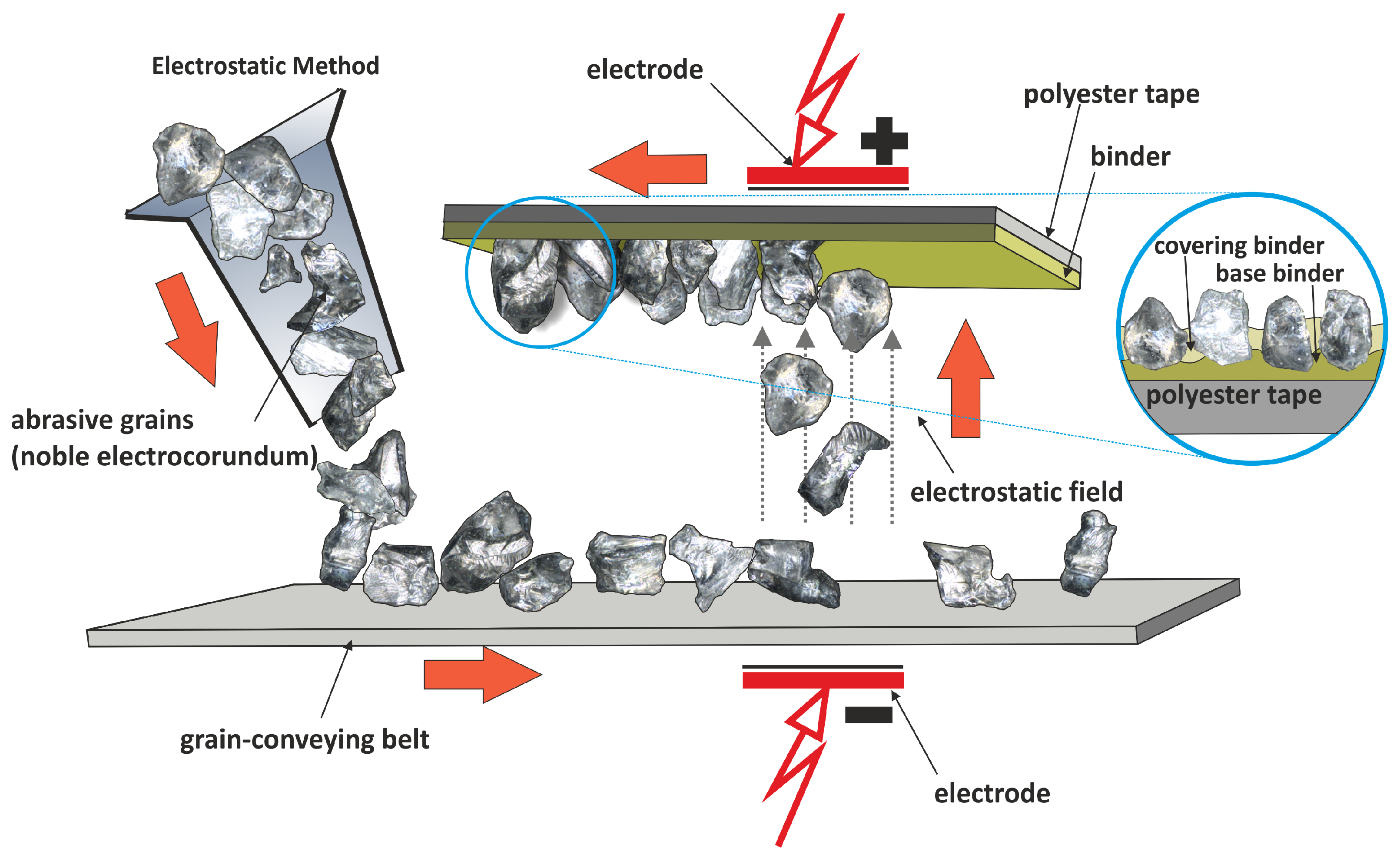
1. Introduction


2. Materials and Methods
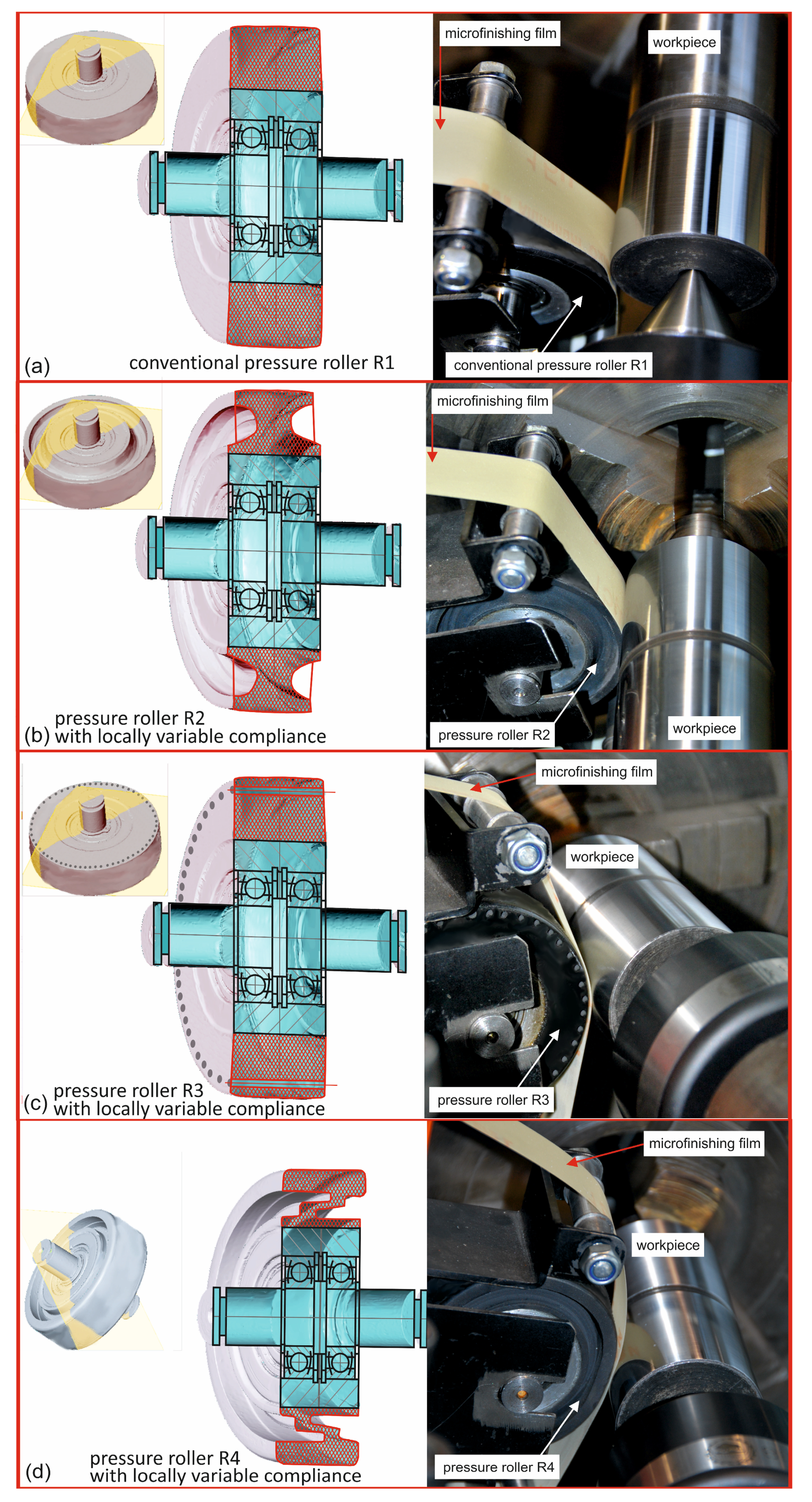
2.1. Pressure Rollers with Locally Variable Compliance
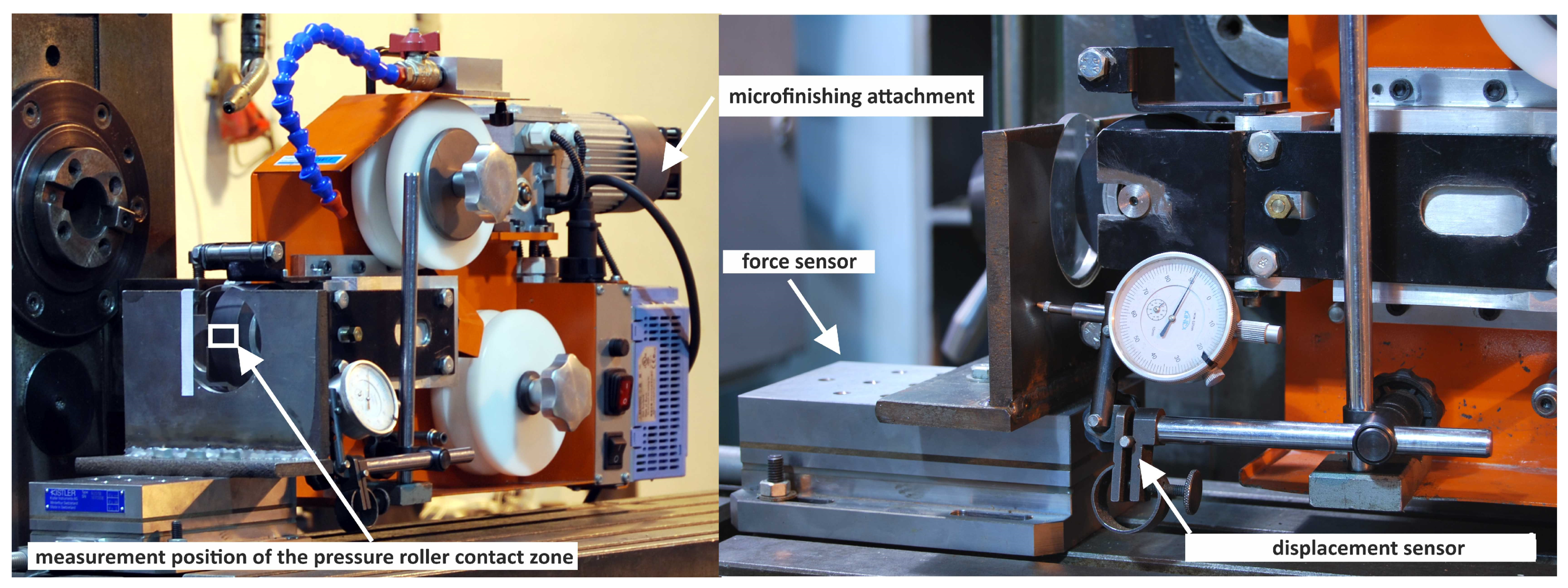
2.2. Research on the Compliance of Pressure Rollers
2.3. Modeling Stress and Material Displacement in Pressure Rollers Using the Finite Element Method
- G—transverse elasticity modulus;
- V—relative volume;
- Cij—Cauchy–Green deformation tensor;
- Δij—Kronecker delta.
- A geometric model of the pressure roller–workpiece system was created.
- The calculation methods and discretization scale were determined.
- The materials used in the simulation, as well as the strength models, were defined.
- The type of contact between the tool and the workpiece material was selected.
- The boundary condition parameters were defined.
2.4. Microfinishing Process Research
3. Results and Discussion
3.1. Experimental Study of Pressure Roller Deflection
3.2. Validation of the Material Model
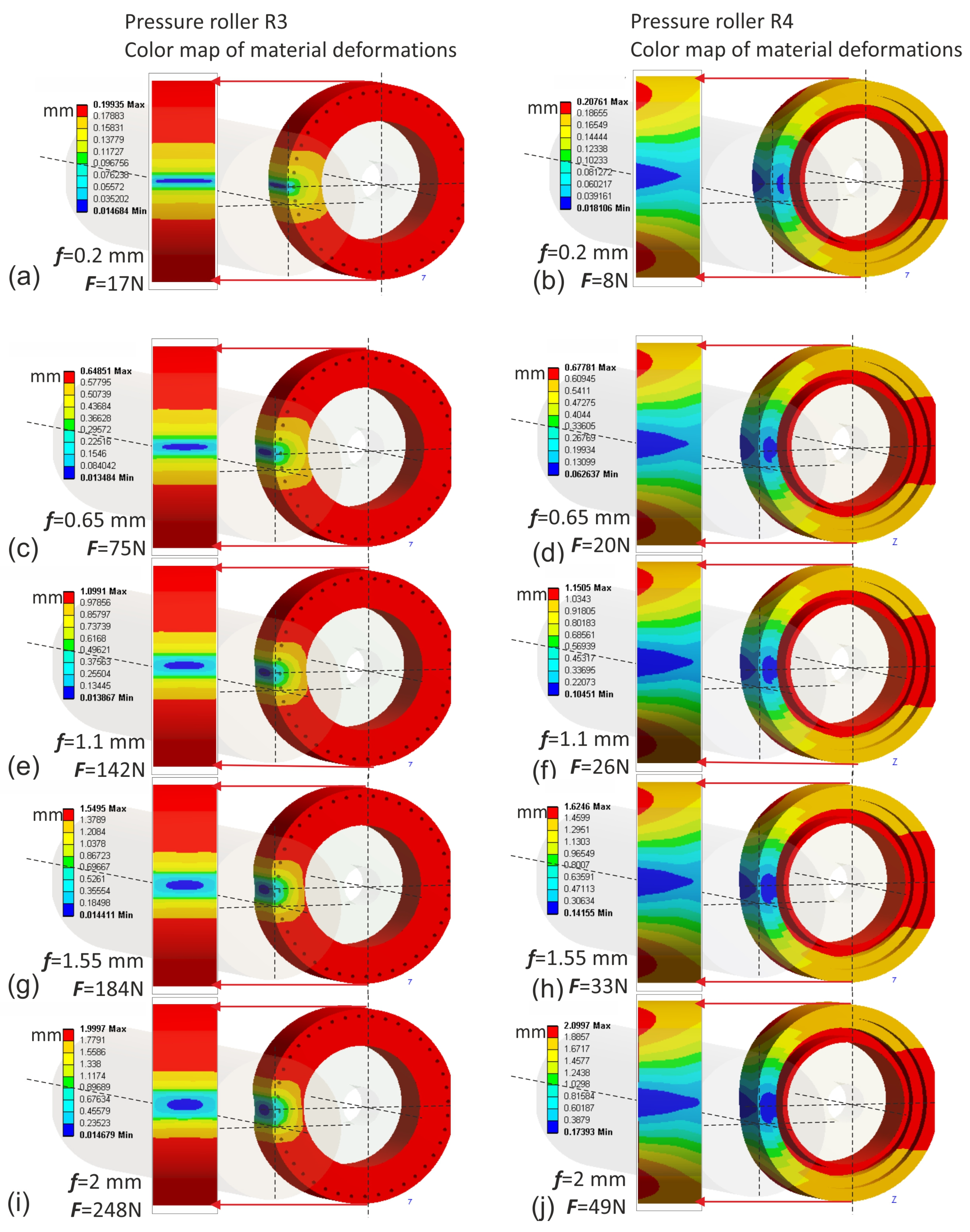
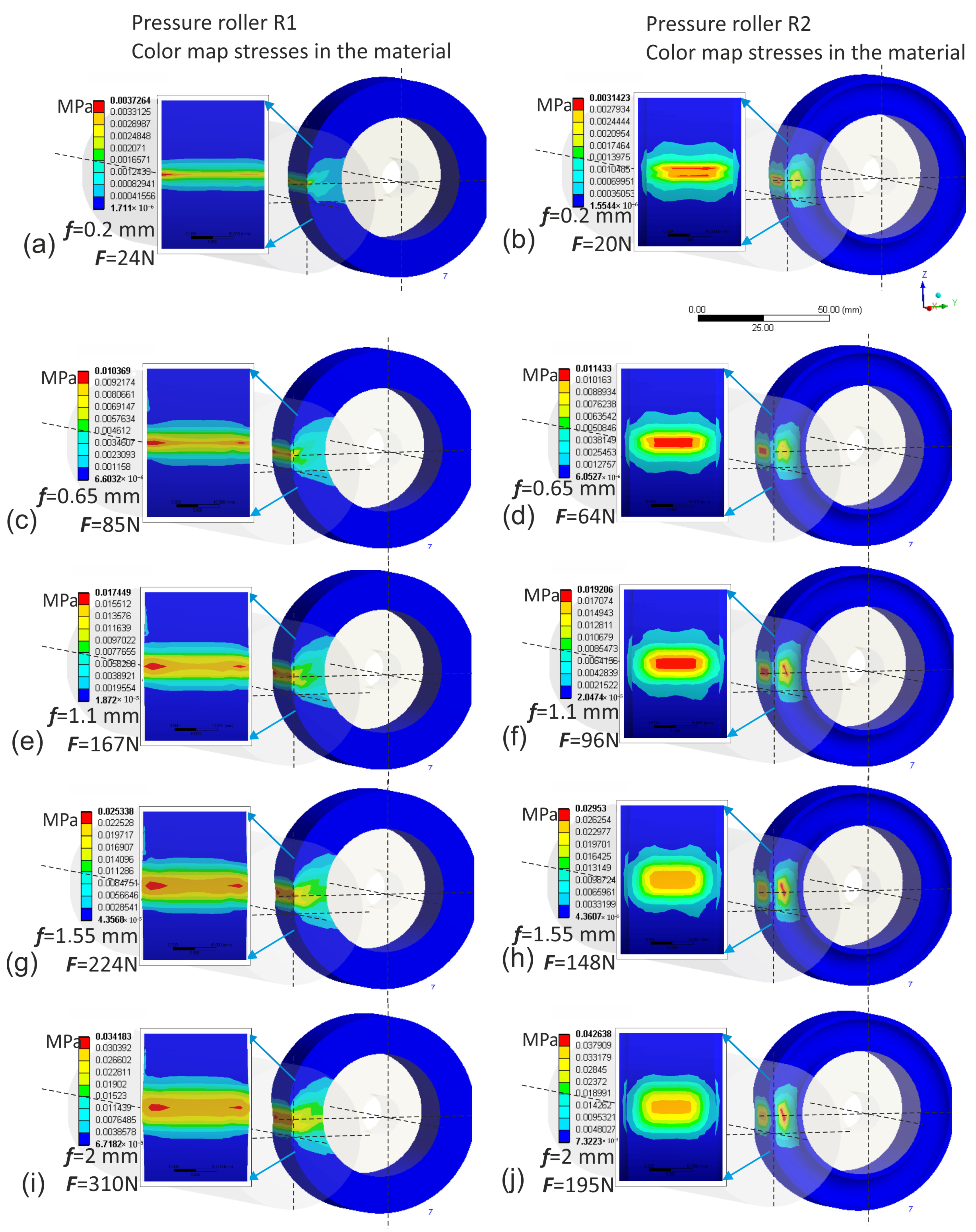
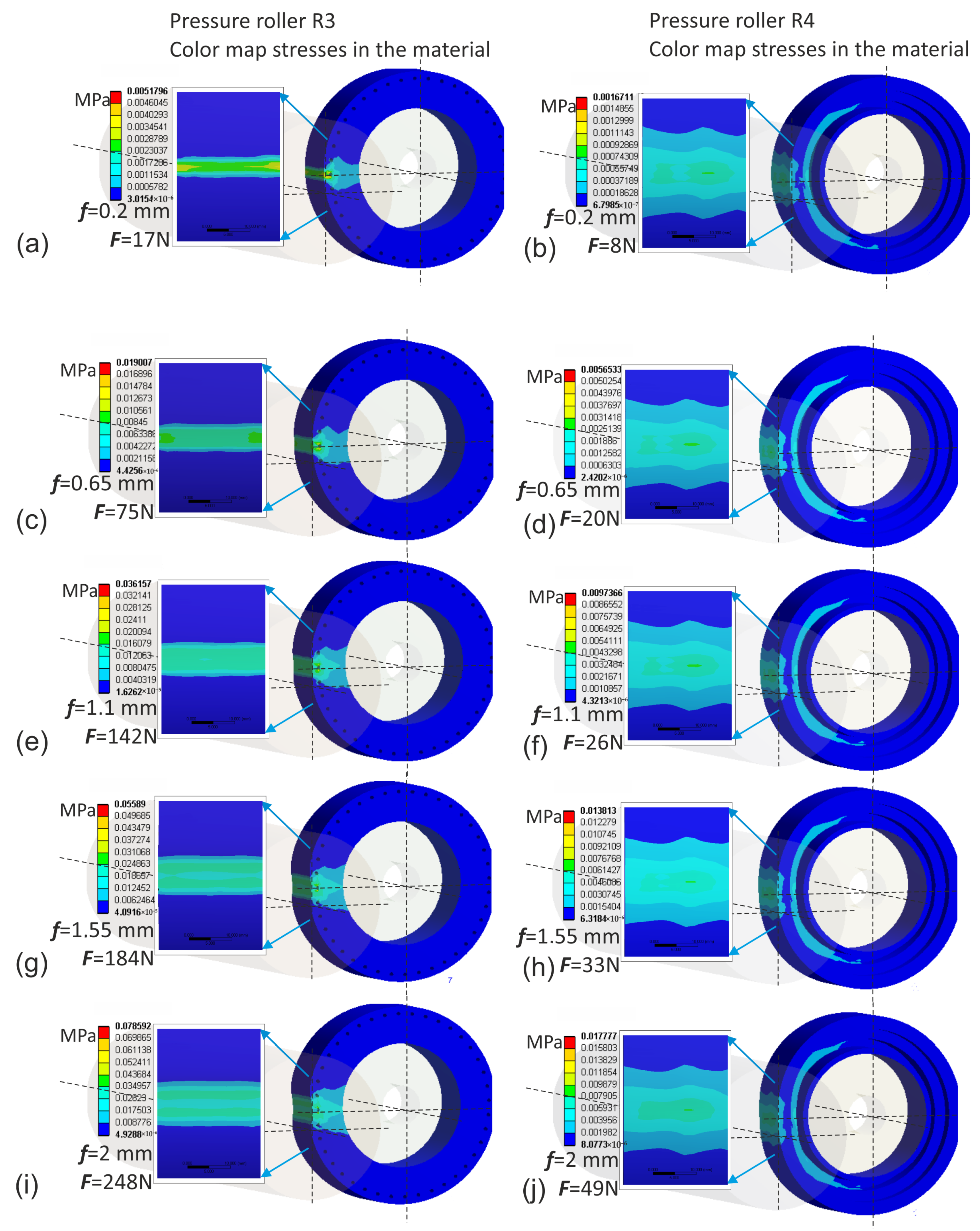
3.3. Dynamic Compression Testing of Rollers Using Finite Element Method Simulation
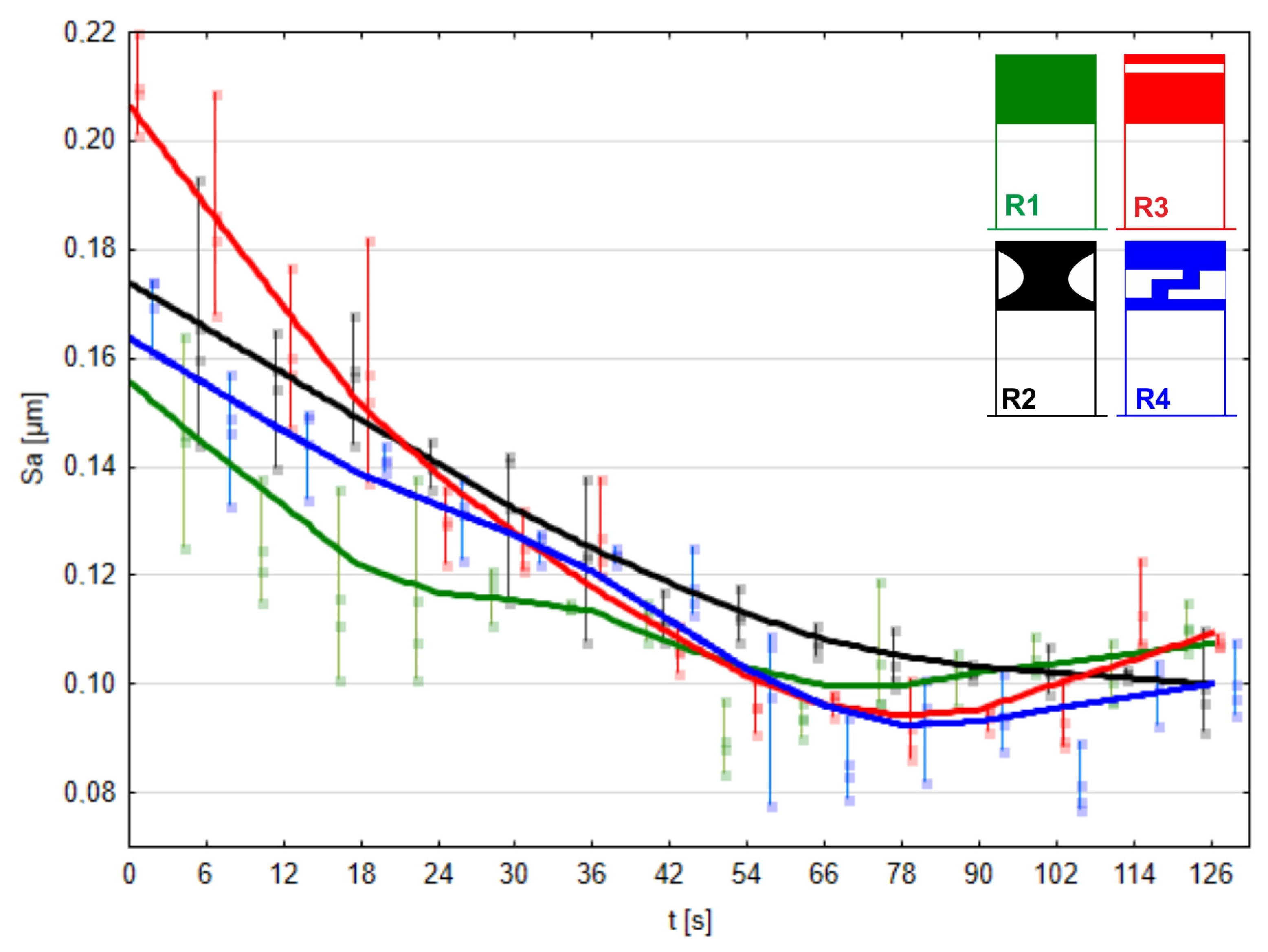
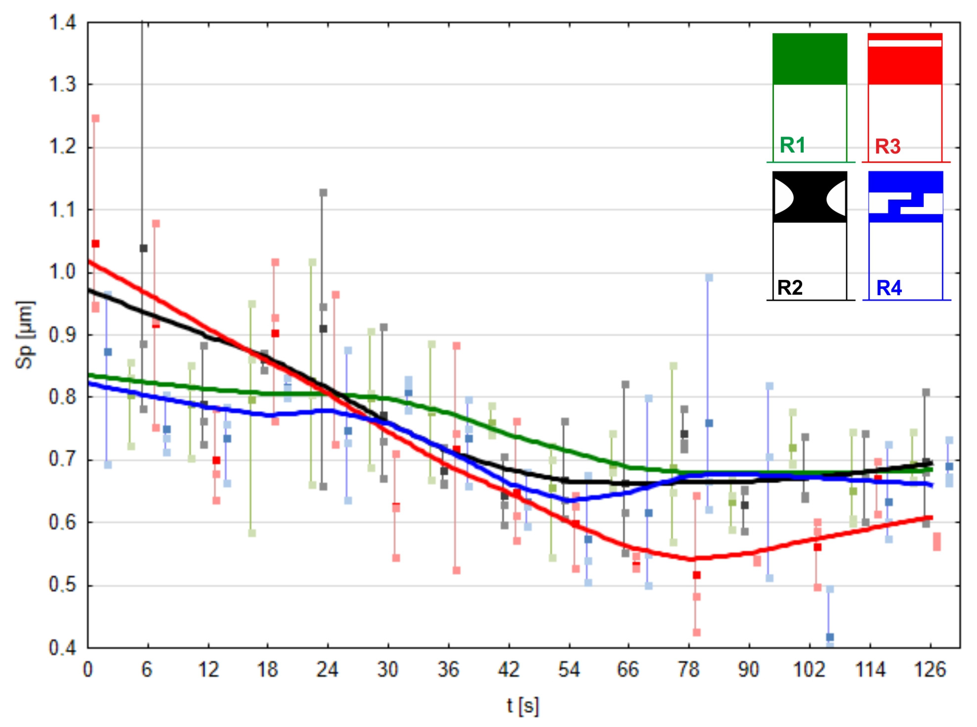
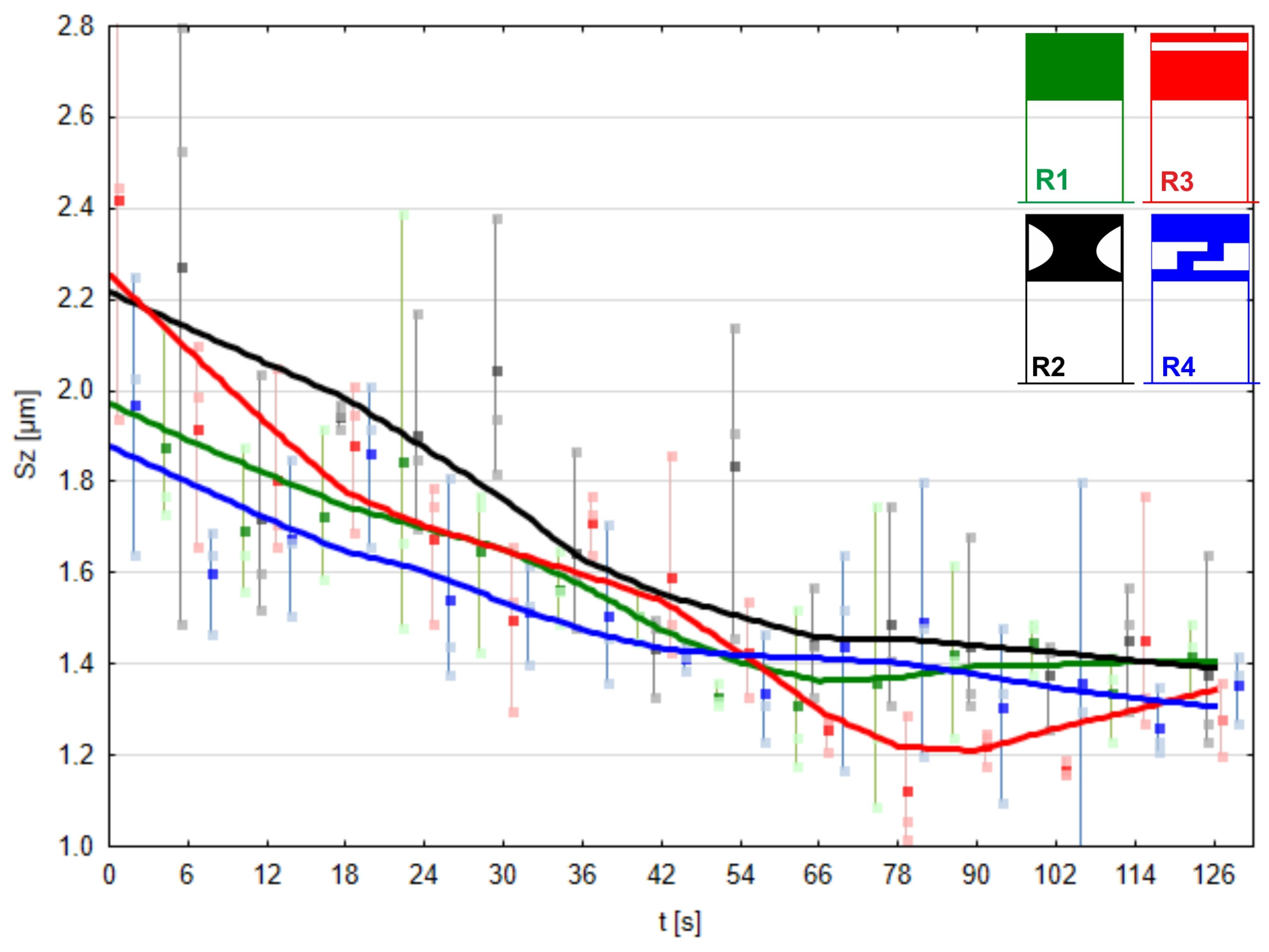
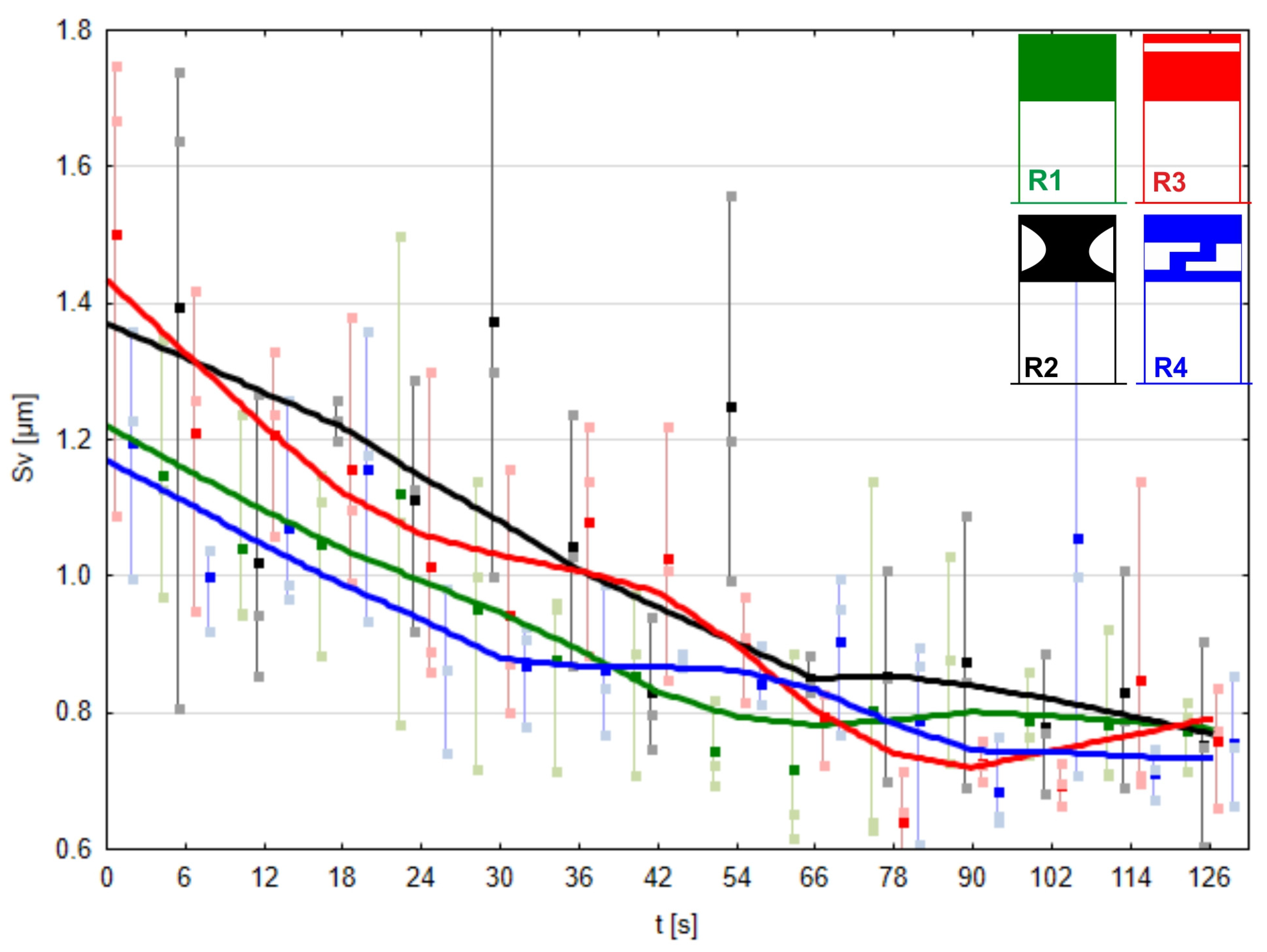
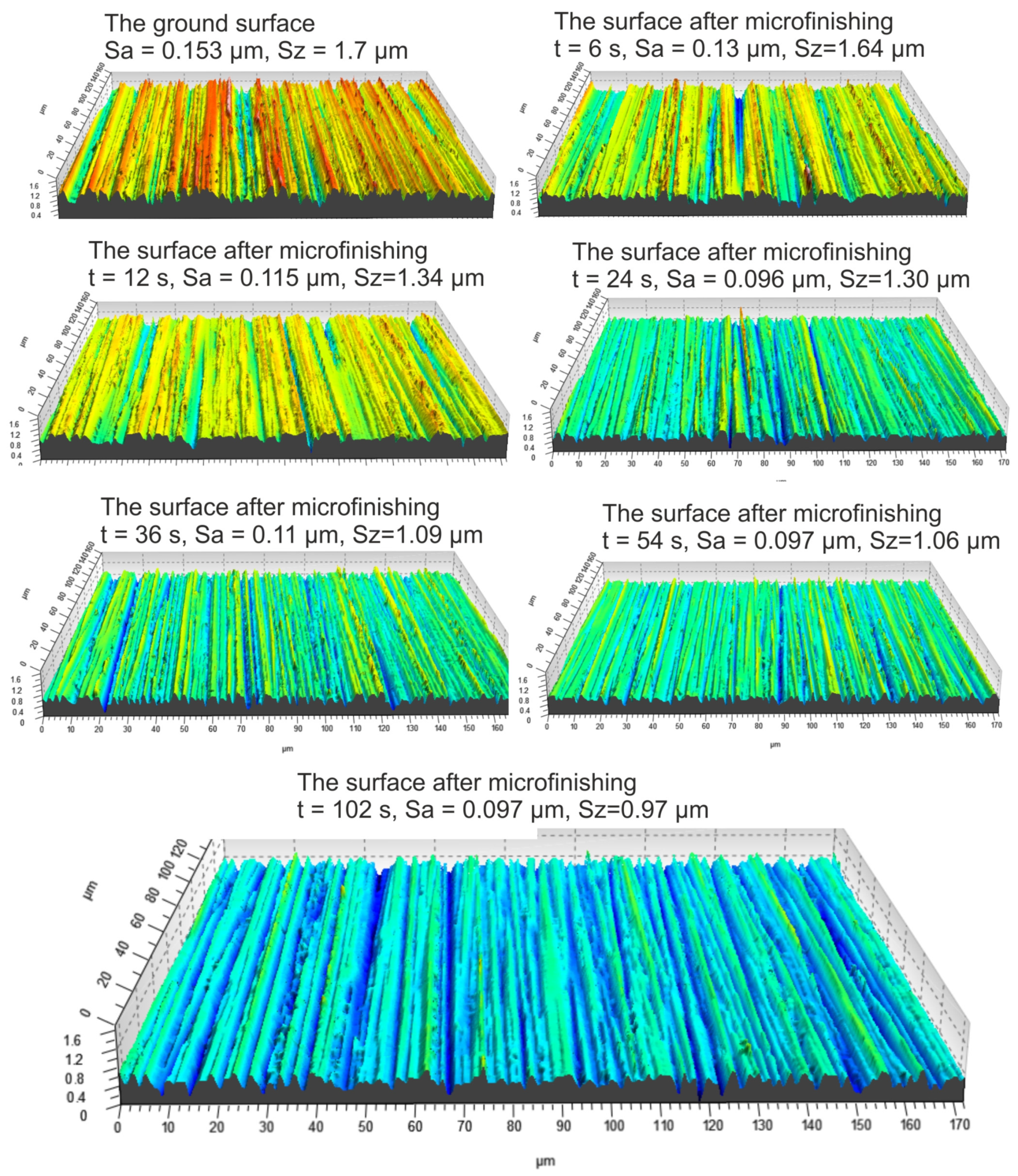
3.4. Experimental Research
- Sp—maximum height of peaks;
- Sv—maximum height of valleys;
- Sz—maximum height of the surface;
- Sa—arithmetical mean height of the surface.
4. Summary and Conclusions
- The applied constitutive material model, utilizing the Blatz-Ko equation to describe the hyperelastic behavior of rubber, was validated through experimental analysis of pressure roller deflection against a flat surface. The agreement between the simulation and experimental results, reaching an overall level of 99.57%, confirms the suitability of the material model for further simulation studies. This validation underscores the importance of selecting an appropriate material model in accurately capturing the elastomer’s behavior under loading conditions, providing confidence in the reliability of subsequent finite element simulations in predicting pressure roller performance and deformation characteristics during microfinishing processes.
- The finite element simulations provided insights into the contact zones of the simulated rollers, varying with the deflection arrow. The analysis revealed distinct patterns of contact, with different pressure distributions and stress concentrations across the contact surfaces. As the deflection increased, the contact area widened, resulting in higher normal force values. Notably, prototype roller R4 exhibited the widest contact zone and the highest compliance, suggesting better adaptation to the machined surface’s curvature. Conversely, the conventional roller R1 demonstrated more localized pressure distribution, indicating a less conforming contact with the workpiece. These findings emphasize the significance of considering deflection-induced variations in contact behavior when designing pressure rollers for microfinishing applications.
- The quality of the obtained surfaces, particularly regarding surface peaks, plays a crucial role in determining the effectiveness of the microfinishing process. The investigation conducted in this study provides valuable insights into the performance of different pressure rollers in removing surface irregularities. Roller R3 exhibited the highest efficacy in removing surface peaks, indicating its potential to achieve superior surface finishes.
Author Contributions
Funding
Institutional Review Board Statement
Informed Consent Statement
Data Availability Statement
Conflicts of Interest
References
- Cabanettes, F.; Cherguy, O.; Courbon, C.; Giovenco, A.; Han, S.; Rech, J. Towards the prediction of surface roughness induced by the belt finishing process: Influence of the workmaterial on the roughness reduction rate. Procedia CIRP 2020, 87, 210–215. [Google Scholar] [CrossRef]
- Wang, W.; Salvatore, F.; Rech, J.; Li, J. Effects of belt’s adhesive wear on surface integrity in dry belt finishing. Procedia CIRP 2018, 71, 31–34. [Google Scholar] [CrossRef]
- Wang, W.; Salvatore, F.; Rech, J.; Li, J. Comprehensive investigation on mechanisms of dry belt grinding on AISI52100 hardened steel. Tribol. Int. 2018, 121, 310–320. [Google Scholar] [CrossRef]
- Hamdi, A.; Merghache, S.M.; Fernini, B.; Aliouane, T. Influence of polymer contacting rollers on surface texture finish in the belt grinding process. Int. J. Adv. Manuf. Technol. 2021, 113, 1377–1388. [Google Scholar] [CrossRef]
- Fan, W.; Wu, C.; Wu, Z.; Liu, Y.; Wang, J. Static contact mechanism between serrated contact wheel and rail in rail grinding with abrasive belt. J. Manuf. Process. 2022, 84, 1229–1245. [Google Scholar] [CrossRef]
- Song, K.; Xiao, G.; Chen, S.; Liu, X.; Huang, Y. A new force-depth model for robotic abrasive belt grinding and confirmation by grinding of the Inconel 718 alloy. Robot. Comput. Integr. Manuf. 2023, 80, 102483. [Google Scholar] [CrossRef]
- Khellouki, A.; Rech, J.; Zahouani, H. The effect of lubrication conditions on belt finishing. Int. J. Mach. Tools Manuf. 2010, 50, 917–921. [Google Scholar] [CrossRef]
- Mezghani, S.; El Mansori, M. Abrasiveness properties assessment of coated abrasives for precision belt grinding. Surf. Coat. Technol. 2008, 203, 786–789. [Google Scholar] [CrossRef]
- Kacalak, W.; Tandecka, K.; Mathia, T.G. A method and new parameters for assessing the active surface topography of diamond abrasive films. J. Mach. Eng. 2016, 16, 95–108. [Google Scholar]
- Kacalak, W.; Lipiński, D.; Szafraniec, F.; Zawada-Tomkiewicz, A.; Tandecka, K.; Królczyk, G. Metrological basis for assessing the state of the active surface of abrasive tools based on parameters characterizing their machining potential. Meas. J. Int. Meas. Confed. 2020, 165, 108068. [Google Scholar] [CrossRef]
- Kacalak, W.; Szafraniec, F.; Lipiński, D.; Banaszek, K.; Rypina, Ł. Modeling and Analysis of Micro-Grinding Processes with the Use of Grinding Wheels with a Conical and Hyperboloid Active Surface. Materials 2022, 15, 5751. [Google Scholar] [CrossRef]
- Lipiński, D.; Banaszek, K.; Rypina, Ł. Analysis of the cutting abilities of the multilayer grinding wheels—Case of Ti-6Al-4V alloy grinding. Materials 2022, 15, 22. [Google Scholar] [CrossRef]
- Cherguy, O.; Cabanettes, F.; Han, S.; Rech, J. Modeling surface roughness profiles generated by the belt finishing process of a 27MnCr5 carburized steel. Precis. Eng. 2024, 88, 148–163. [Google Scholar] [CrossRef]
- Szada-Borzyszkowska, M.; Kacalak, W.; Lipiński, D.; Bałasz, B. Analysis of the erosivity of high-pressure pulsating water jets produced in the self-excited drill head. Materials 2021, 14, 4165. [Google Scholar] [CrossRef] [PubMed]
- Płodzień, M.; Żyłka, Ł.; Żak, K.; Wojciechowski, S. Modelling the Kerf Angle, Roughness and Waviness of the Surface of Inconel 718 in an Abrasive Water Jet Cutting Process. Materials 2023, 16, 5288. [Google Scholar] [CrossRef]
- Song, K.; Xiao, G.; Chen, S.; Li, S. Analysis of thermal-mechanical causes of abrasive belt grinding for titanium alloy. Int. J. Adv. Manuf. Technol. 2021, 113, 3241–3260. [Google Scholar] [CrossRef]
- Liu, Y.; Xu, J.; Xiao, G.; Zhou, K.; Liu, G. Thermo-mechanical coupling during belt grinding and corresponding surface integrity of titanium alloy. Int. J. Adv. Manuf. Technol. 2022, 121, 6599–6609. [Google Scholar] [CrossRef]
- Xiao, G.; Zhang, Y.; Zhu, B.; Gao, H.; Huang, Y.; Zhou, K. Wear behavior of alumina abrasive belt and its effect on surface integrity of titanium alloy during conventional and creep-feed grinding. Wear 2023, 514–515, 204581. [Google Scholar] [CrossRef]
- Wang, Y.; Huang, X.; Ren, X.; Chai, Z.; Chen, X. In-process belt-image-based material removal rate monitoring for abrasive belt grinding using CatBoost algorithm. Int. J. Adv. Manuf. Technol. 2022, 123, 2575–2591. [Google Scholar] [CrossRef]
- Liu, Y.; Song, S.; Xiao, G.; Huang, Y.; Zhou, K. A high-precision prediction model for surface topography of abrasive belt grinding considering elastic contact. Int. J. Adv. Manuf. Technol. 2023, 125, 777–792. [Google Scholar] [CrossRef]
- Han, C.; Zhou, M.; Zou, L.; Luo, L.; Li, H.; Wang, W. Study on nickel-based single crystal superalloy DD6 subsurface damage of belt grinding with a large cutting depth of one pass. Eng. Fail. Anal. 2024, 161, 108256. [Google Scholar] [CrossRef]
- Zhang, B.; Wu, S.; Wang, D.; Yang, S.; Jiang, F.; Li, C. A review of surface quality control technology for robotic abrasive belt grinding of aero-engine blades. Meas. J. Int. Meas. Confed. 2023, 220, 113381. [Google Scholar] [CrossRef]
- Wang, W.; Salvatore, F.; Rech, J.; Li, J. Investigating adhesion wear on belt and its effects on dry belt finishing. J. Brazilian Soc. Mech. Sci. Eng. 2018, 40, 2119–2123. [Google Scholar] [CrossRef]
- Serpin, K.; Mezghani, S.; El Mansori, M. Multiscale assessment of structured coated abrasive grits in belt finishing process. Wear 2015, 332–333, 780–787. [Google Scholar] [CrossRef]
- Chen, F.; Peng, X.; Sun, Z.; Hu, H.; Dai, Y.; Lai, T. Modeling and Experimental Verification of Time-Controlled Grinding Removal Function for Optical Components. Micromachines 2023, 14, 1384. [Google Scholar] [CrossRef] [PubMed]
- Li, H.; Zou, L.; Wang, W.; Li, H. Introducing abrasive wear into undeformed chip thickness modeling with improved grain kinematics in belt grinding. J. Manuf. Process. 2023, 108, 903–915. [Google Scholar] [CrossRef]
- Serpin, K.; Mezghani, S.; El Mansori, M. Wear study of structured coated belts in advanced abrasive belt finishing. Surf. Coatings Technol. 2015, 284, 365–376. [Google Scholar] [CrossRef]
- Bigerelle, M.; Hagege, B.; El Mansori, M. Mechanical modelling of micro-scale abrasion in superfinish belt grinding. Tribol. Int. 2008, 41, 992–1001. [Google Scholar] [CrossRef]
- Sun, Z.; Hu, H.; Dai, Y.; Guan, C.; Tie, G.; Ou, Y. Frequency domain analysis and precision realization in deterministic figuring of ultra-precision shaft parts. Materials 2020, 13, 4561. [Google Scholar] [CrossRef]
- Jourani, A.; Dursapt, M.; Hamdi, H.; Rech, J.; Zahouani, H. Effect of the belt grinding on the surface texture: Modeling of the contact and abrasive wear. Wear 2005, 259, 1137–1143. [Google Scholar] [CrossRef]
- Bouktib, N.; Khellouki, A. Investigation of belt-finishing effect on the residual stress field through repeated scratching on rough hard-turned surface. Tribol. Int. 2021, 153, 106644. [Google Scholar] [CrossRef]
- Sun, Z.; Dai, Y.; Hu, H.; Tie, G.; Guan, C.; Chen, X. Research on deterministic figuring of ultra-precision shaft parts based on analysis and control of figuring ability. Materials 2020, 13, 2458. [Google Scholar] [CrossRef]
- Chen, X.; Dai, Y.; Hu, H.; Tie, G.; Guan, C. Research on high precision and deterministic figuring for shaft parts based on abrasive belt polishing. Materials 2019, 12, 1389. [Google Scholar] [CrossRef]
- Tandecka, K.; Kacalak, W.; Wiliński, M.; Wieczorowski, M.; Mathia, T.G. Morphology of Microchips in the Surface Finishing Process Utilizing Abrasive Films. Materials 2024, 17, 688. [Google Scholar] [CrossRef]
- Tandecka, K.; Kacalak, W.; Wiliński, M.; Wieczorowski, M.; Mathia, T.G. Superfinishing with Abrasive Films Featuring Discontinuous. Materials 2024, 17, 1704. [Google Scholar] [CrossRef]
- Courbon, C.; Valiorgue, F.; Claudin, C.; Jacquier, M.; Dumont, F.; Rech, J. Influence of Some Superfinishing Processes on Surface Integrity in Automotive Industry. Procedia CIRP 2016, 45, 99–102. [Google Scholar] [CrossRef]
- Mezghani, S.; El Mansori, M.; Zahouani, H. New criterion of grain size choice for optimal surface texture and tolerance in belt finishing production. Wear 2009, 266, 578–580. [Google Scholar] [CrossRef]
- Li, M.; Zhao, S.; Li, H.; Huang, Y.; Zou, L.; Wang, W. On Energy Assessment of Titanium Alloys Belt Grinding Involving Abrasive Wear Effects. Chin. J. Mech. Eng. 2023, 36, 115. [Google Scholar] [CrossRef]
- Rech, J.; Kermouche, G.; Claudin, C.; Khellouki, A.; Grzesik, W. Modelling of the residual stresses induced by belt finishing on a AISI52100 hardened steel. Int. J. Mater. Form. 2008, 1, 567–570. [Google Scholar] [CrossRef]
- Balzani, D.; Brinkhues, S.; Holzapfel, G.A. Constitutive Modelling and Parameter Identification for Rubber-Like Materials. Comput. Methods Appl. Mech. Eng. 2012, 213–216, 139–151. [Google Scholar] [CrossRef]
- Qu, Z.; He, W.; Lv, M.; Xiao, H. Large-strain hyperelastic constitutive model of envelope material under biaxial tension with different stress ratios. Materials 2018, 11, 1780. [Google Scholar] [CrossRef] [PubMed]
- Hadoush, A. Internally Balanced Elasticity Tensor in Terms of Principal Stretches. J. Elast. 2024. [Google Scholar] [CrossRef]
- Horgan, C.O.; Murphy, J.G. Simple Shear and Applied Piola-Kirchhoff Shear Stress. J. Elast. 2022. [Google Scholar] [CrossRef]
- Peyraut, F. Loading restrictions for the Blatz-Ko hyperelastic model—Application to a finite element analysis. Int. J. Non. Linear. Mech. 2004, 39, 969–976. [Google Scholar] [CrossRef]
- ISO 25178-2:2021; Geometrical Product Specifications (GPS): Surface Texture: Areal—Part 2: Terms, Definitions and Surface Texture Parameters. ISO: Geneva, Switzerland, 2021.


| Workpiece Material (Steel) | |
|---|---|
| Density | 7.85 × 10⁻⁶ kg mm−3 |
| Coefficient of Thermal Expansion | 1.2 × 10⁻⁵ C−1 |
| Specific Heat | 4.34 × 10⁵ mJ kg−1 C−1 |
| Thermal Conductivity | 6.05 × 10⁻² W mm−1 C−1 |
| Resistivity | 1.7 × 10⁻⁴ ohm mm |
| Compressive Yield Strength | 250 MPa |
| Tensile Yield Strength | 250 MPa |
| Tensile Ultimate Strength | 460 MPa |
| Reference Temperature | 22 °C |
| Blatz-Ko constitutive model (elastomer) | |
| Density | 2 × 10⁻⁶ kg mm−3 |
| Initial Shear Modulus Mu | 6.5 × 10⁻² MPa |
| Workpiece Material | Chrome Steel (41Cr4) |
|---|---|
| Pressure roll hardness | 80°Sh |
| Pressure force | 60 N |
| Tool speed | 160 mm/min |
| Workpiece speed | 35 m/min |
Disclaimer/Publisher’s Note: The statements, opinions and data contained in all publications are solely those of the individual author(s) and contributor(s) and not of MDPI and/or the editor(s). MDPI and/or the editor(s) disclaim responsibility for any injury to people or property resulting from any ideas, methods, instructions or products referred to in the content. |
© 2024 by the authors. Licensee MDPI, Basel, Switzerland. This article is an open access article distributed under the terms and conditions of the Creative Commons Attribution (CC BY) license (https://creativecommons.org/licenses/by/4.0/).
Share and Cite
Tandecka, K.; Kacalak, W.; Rypina, Ł.; Wiliński, M.; Wieczorowski, M.; Mathia, T.G. Effects of Pressure Rollers with Variable Compliance in the Microfinishing Process Utilizing Abrasive Films. Materials 2024, 17, 1795. https://doi.org/10.3390/ma17081795
Tandecka K, Kacalak W, Rypina Ł, Wiliński M, Wieczorowski M, Mathia TG. Effects of Pressure Rollers with Variable Compliance in the Microfinishing Process Utilizing Abrasive Films. Materials. 2024; 17(8):1795. https://doi.org/10.3390/ma17081795
Chicago/Turabian StyleTandecka, Katarzyna, Wojciech Kacalak, Łukasz Rypina, Maciej Wiliński, Michał Wieczorowski, and Thomas G. Mathia. 2024. "Effects of Pressure Rollers with Variable Compliance in the Microfinishing Process Utilizing Abrasive Films" Materials 17, no. 8: 1795. https://doi.org/10.3390/ma17081795
APA StyleTandecka, K., Kacalak, W., Rypina, Ł., Wiliński, M., Wieczorowski, M., & Mathia, T. G. (2024). Effects of Pressure Rollers with Variable Compliance in the Microfinishing Process Utilizing Abrasive Films. Materials, 17(8), 1795. https://doi.org/10.3390/ma17081795