
Revisiting Intercalation Anode Materials for Potassium-Ion Batteries


Abstract
1. Introduction

| Properties | Li | Na | K |
|---|---|---|---|
| Atomic mass, u | 6.941 | 22.989 | 39.098 |
| Melting point, °C | 180.5 | 97.7 | 63.4 |
| Atomic radius, pm | 145 | 180 | 220 |
| Ionic radius, Å [27] | 0.76 | 1.02 | 1.38 |
| Stokes radius in water, Å [28] | 2.38 | 1.84 | 1.25 |
| Stokes radius in PC, Å [29] | 4.8 | 4.6 | 3.6 |
| Voltage (A+/A) vs. SHE, 1 V [30] | −3.04 | −2.71 | −2.93 |
| Voltage (A+/A) vs. Li+/Li in PC, V [30] | 0 | 0.23 | −0.09 |
| Voltage (A+/A) vs. Li+/Li in EC:DEC, V [31] | 0 | - | −0.15 |
| Theoretical capacity of graphite, mAh g−1 [32] | 372 | 111.7 2 | 279 |
| Crust abundance, mass % [22] | 0.0017 | 2.4 | 2.1 |
| Distribution [20] | 70% S. Am. 3 | Global | Global |
| Cost of carbonate [33], 4 USD ton−1 | 13,860 | 350 | 1540 |
2. Carbon-Based Intercalation Anodes
2.1. Graphite
2.1.1. Mechanism
2.1.2. Diffusion Coefficients, Formation Enthalpy, and Safety
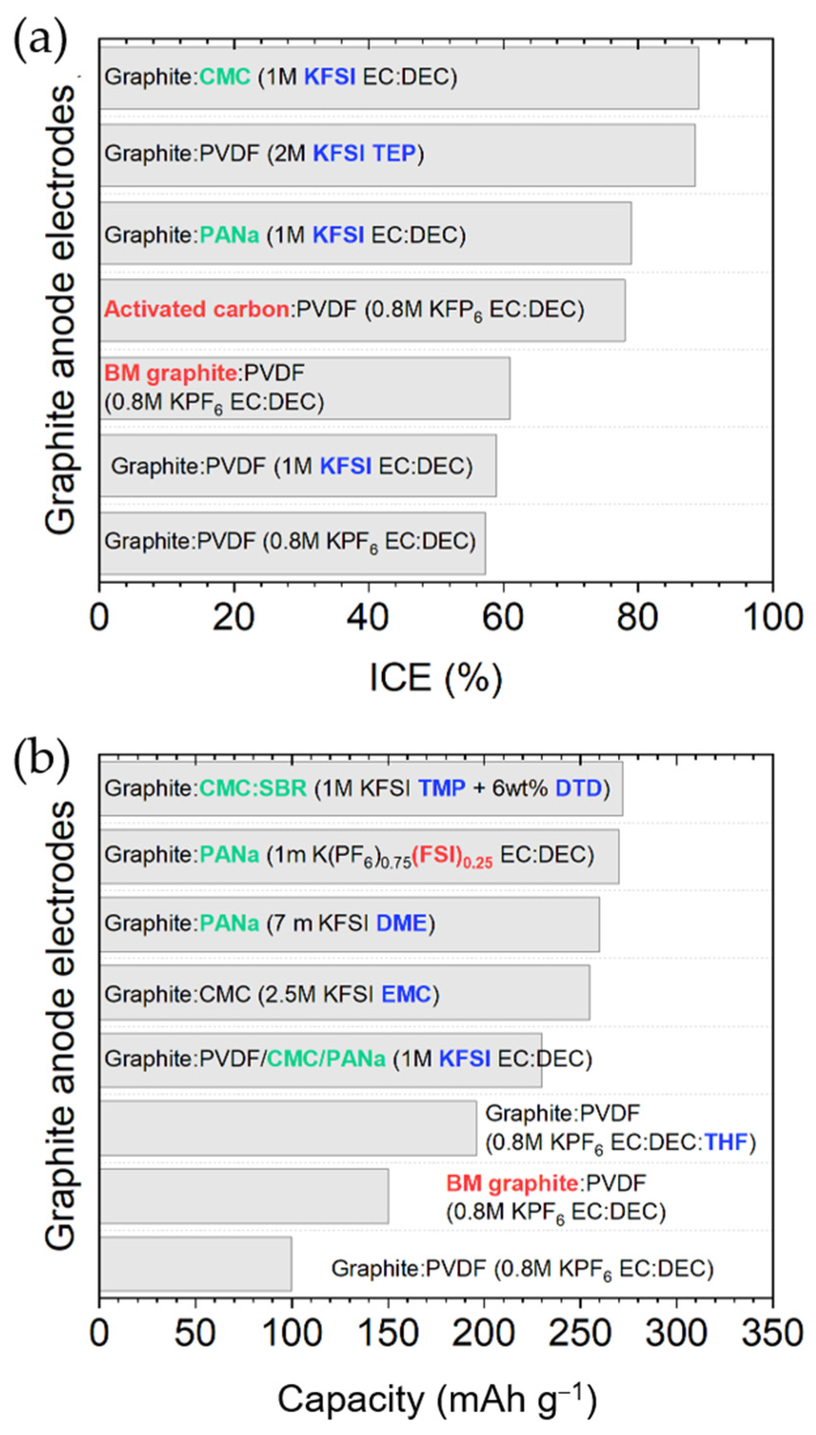
2.1.3. Binder and Electrolyte Optimization to Extend the ICE and Cyclability

2.1.4. Graphite Structure Engineering to Enhance Its Performance
| Cyclability | Rate Capability | ||||||
|---|---|---|---|---|---|---|---|
| Anode Material | Electrolyte | Binder | ICE | Capacity (mAh g−1) | Cycle Number@ Current Density (A g−1) | Capacity (mAh g−1)@ Current Density (A g−1) | Ref. |
| Graphite (TIMCAL) | 0.8 M KPF6/EC:DEC | PVDF | 57.4% | ~100 | 50 cycles@0.14 | ~75@0.28 | [32] |
| Graphite (GT) | 0.5 M KPF6/EC:DEC | PVDF | 74% | 207 | N/A | ~88@0.2 | [42] |
| Natural graphite | 1 M KFSI/EC:DEC | PANa | 79% | ~230 | 50 cycles@0.028 | 225@4.19 | [31] |
| Natural graphite | 1 M KFSI/EC:DEC | CMC | 89% | ~230 | 8 cycles@0.028 | N/A | [31] |
| Natural graphite | 1 M KFSI/EC:DEC | PVDF | 59% | ~230 | 20 cycles@0.028 | N/A | [31] |
| Graphite | 1 M KPF6/EC:PC | Na-alginate | 66.5% | ~230 | 200 cycles@0.02 | N/A | [44] |
| MLGF 1 | 1 M KPF6/DEGDME | Free | 73% | 95 | 1000 cycles@2 | ~80@10 | [54] |
| Natural graphite | 1 M KPF6/DME | CMC | 87.4% | 73 | 3500 cycles@2.8 | 87@2.8 | [55] |
| Flake graphite | 0.5 M KPF6/DEGDME | PVDF | 90% | 80.8 | 50 cycles@0.025 | N/A | [56] |
| Graphite | 0.8 M KPF6/EC:DEC:THF | PVDF | 54% | 196 | 100 cycles@0.093 | ~80@0.28 | [57] |
| Graphite | 7 m KFSI/DME | PANa | ~78% | ~260 | 300 cycles@0.025 | ~200@0.75 | [59] |
| Graphite | 1 m KFSI/Pyr1,3FSI | PAA 2 | ~80% | 233 | 400 cycles@C/5 | ~216@2C | [60] |
| Graphite | 2.5 M KFSI/EMC | CMC | ~80% | 255 | 2000 cycles@0.093 | N/A | [61] |
| Graphite | 1 m K(PF6)0.75(FSI)0.25/EC:DEC | PANa | 89% | 270 | 100 cycles@0.025 | N/A | [63] |
| Graphite | 2 M KFSI/TEP | PVDF | 88.5% | ~250 | 300 cycles@0.056 | ~130@0.56 | [64] |
| Graphite | KFSI/TMP (8: 3) | PVDF | ~58% | ~204 | 2000 cycles@0.056 | ~100@0.56 | [65] |
| Graphite | 0.8 M KPF6/EC: EMC + artif. SEI | CMC | 93% | ~260 | 1000 cycles@0.1 | ~100@0.5 | [66] |
| Graphite | 0.75 m KPF6/EC:DEC + 10 wt.% DMSF | CMC | ~84% | ~240 | 25 cycles@0.1C | ~225@1C | [69] |
| Graphite | 0.75 m KPF6/EC:DEC + 10 wt.% KFSI | CMC | ~89% | ~240 | 25 cycles@0.1C | ~225@1C | [69] |
| Graphite | 1 M KFSI/TMP + 6 wt% DTD | CMC+SBR | 86.6% | 272 | 100 cycles@0.028 | ~225@0.67 | [70] |
| Graphite | 1 M KFSI/EC: DEC + DTD + CAPE | CMC | ~76% | ~250 | 1500 cycles@0.1 | N/A | [71] |
| Graphite | 1 M KPF6/DEE + 1 wt.% TEE | N/A | ~75% | ~250 | 220 cycles@0.1 | N/A | [72] |
| BM graphite | 0.8 M KPF6/EC:DEC | PVDF | 61% | 150 | 100 cycles@0.025 | ~200@0.25 | [76] |
| BM graphite flakes | 0.75 M KPF6/EC:DEC | CMC | 74% | 222 | 500 cycles@0.1 | 226@4 | [77] |
| Activated carbon | 0.8 M KPF6/EC:DEC | PVDF | ~78% | 100 | 100 cycles@0.2 | 114@0.4 | [78] |
| Expanded graphite | 0.5 M KPF6/EC:DEC | PVDF | ~51% | 192 | 100 cycles@0.1 | 88@1.5 | [79] |
| Expanded graphite | 1 M KFSI/EC:DEC | CMC | 81.6% | 228 | 200 cycles@0.05 | 180@0.2 | [80] |
| Expanded graphite | 0.8 M KPF6/EC:DEC | PVDF | 39.5% | 158 | 1000 cycles@0.2 | 106@1 | [81] |
| Polynanographite | 0.8 M KPF6/EC:DEC | CMC | 54.1% | 75 | 240 cycles@0.1 | 43.2@0.5 | [82] |
| Pencil-trace anode | 0.8 M KPF6/EC:DEC | Free | ~65% | ~170 | 350 cycles@0.4 | ~115@1 | [83] |
| N-doped GT foam | 1 M KFSI/EC:DEC | Free | 59% | ~170 | 200 cycles@0.4 | 112@0.2 | [86] |
| Rich N-doped GT | 1 M KFSI/DME | PVDF | 48.7% | 266 | 100 cycles@0.5 | 112 @0.2 | [87] |
| K-enriched GT | 5 m KFSI/EC:DEC | PVDF | ~85% | ~215 | 200 cycles@0.025 | N/A | [88] |
2.2. Graphene
| Cyclability | Rate Capability | |||||||
|---|---|---|---|---|---|---|---|---|
| Anode Material | Electrolyte | Binder | ICE | Initial Capacity (mAh g−1)@ Current Density (A g−1) | Capacity (mAh g−1) | Cycle Number@ Current Density (A g−1) | Capacity (mAh g−1)@ Current Density (A g−1) | Ref. |
| S-s. rGO 1 | 0.5 M KPF6/EC:DEC | Free | ~50% | ~222@0.010 | ~107 | 150 cycles@0.010 | 50@0.1 | [42] |
| S.s. rGO aerogel 1 | 0.7 M KPF6/EC:DEC | Free | 44% | 267@0.026 | 230 | 100 cycles@0.026 | ~100@0.523 | [90] |
| rGO-2500 | 0.5 M KPF6/DEGDME | PVDF | 62% | 125@0.1 | 88.4 | 2500 cycles@0.1 | ~60@1.1 | [91] |
| FLG 2 on Ni foam | 0.8 M KPF6/EC:DEC | Free | N/A | ~210@0.1 | ~140–150 | 100 cycles@0.1 | ~62@0.1 | [92] |
| FLG microspheres | 0.8 M KPF6/EC:DMC + artif. SEI | CMC | 94% | 285@0.05 | 230 | 1000 cycles@0.2 | 95@1 | [93] |
| F-doped FLG foam | 0.8 M KPF6/EC:DEC | PVDF | 41.2% | 356@0.05 | 166 | 200 cycles@0.5 | 213@0.5 | [94] |
| N-doped FLG | 0.8 M KPF6/EC:DEC | Free | ~87% | 270@0.05 | 210 | 100 cycles@0.1 | ~50@0.2 | [95] |
| N-doped monolith | 0.8 M KPF6/EC:DEC | CMC | ~15% | 487@0.02 | 150 | 1000 cycles@0.5 | ~180@5 | [96] |
| S-s. S-doped rGO | 1 M KPF6/EC:PC | Free | 65% | 456@0.05 | 361 | 50 cycles@0.05 | 224@1 | [97] |
| P/O-doped graphene | 1 M KClO4/EC:DEC | PVDF | 22.6% | 566@0.05 | ~400 | 600 cycles@0.5 | 222@1 | [98] |
| N/P-doped MLG 3 | 1 M KPF6/EC:DEC | PVDF | 15% | 387@0.05 | 242 | 500 cycles@0.5 | 194@1 | [99] |
| N/P-doped G on CC 4 | 1 M KPF6/EC:DEC + 5wt%FEC | Free | 53% | 366@0.025 | 281 | 1000 cycles@0.025 | 186@1 | [100] |
| N/O-doped G-l CNC 5 | 1 M KPF6/DEGDME | CMC | N/A | ~185@0.5 | 130 | 300 cycles@0.5 | 114@1 | [101] |
| N/S-doped G nrbs 6 | 0.8 M KPF6/EC:DEC | PAA | 55% | ~267@0.5 | 224 | 500 cycles@0.5 | 212@1 | [102] |
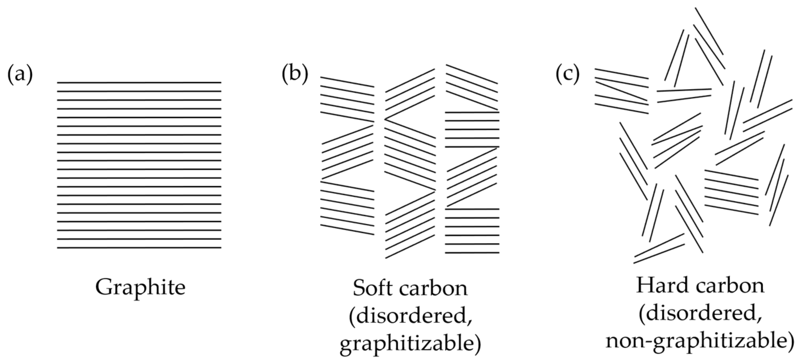
2.3. Soft and Hard Carbons
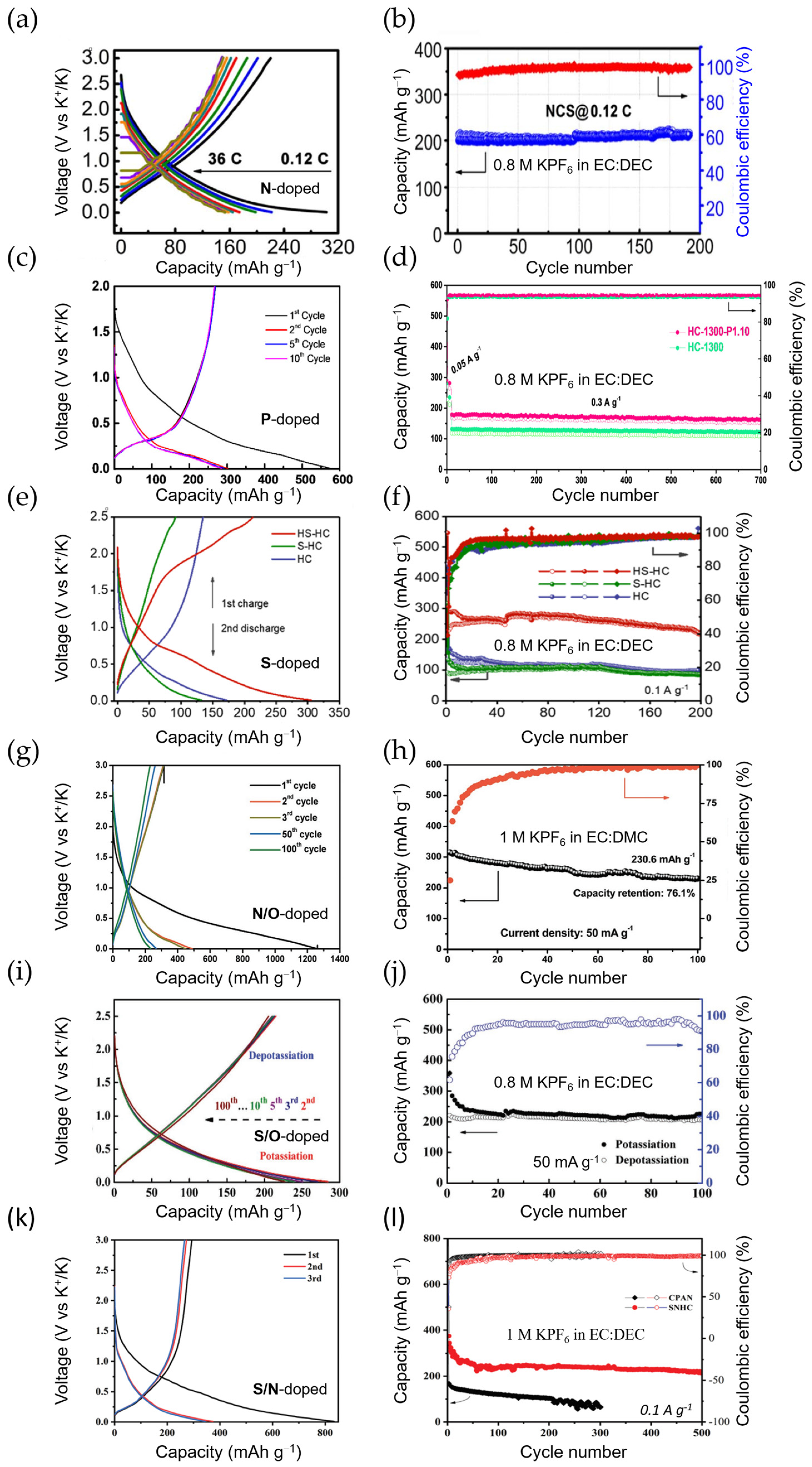
2.4. Other Carbonaceous Anode Materials
| Cyclability | Rate Capability | |||||||
|---|---|---|---|---|---|---|---|---|
| Anode Material | Electrolyte | Binder | ICE | Initial Capacity (mAh g−1)@ Current Density (A g−1) | Capacity (mAh g−1) | Cycle Number@ Current Density (A g−1) | Capacity (mAh g−1)@ Current Density (A g−1) | Ref. |
| S-s. CNF paper 1 (N/O-doped) | 0.8 M KPF6/EC:DEC | Free | 24.1% | 272@0.2 223@0.2 | 270 211 | 80 cycles@0.02 1200 cycles@0.2 | 100@7.7 | [132] |
| S-s. N/O-doped CNF 1 | 0.8 M KPF6/EC:DEC | Free | 35% | ~280@0.028 ~190@0.28 | 170 | 1900 cycles@0.28 | ~120@1.4 | [133] |
| N-doped (chitin-d) 2 CNF | 0.8 M KPF6/EC:DEC | Na-alginate | 37.8% | 215@0.056 | ~200 103 | 100 cycles@0.056 500 cycles@0.56 | ~85 @1.4 | [134] |
| N-doped CNF | 0.8 M KPF6/EC:PC | CMC | 49% | 368@0.025 | 248 146 | 100 cycles@0.25 4000 cycles@2 | 101@20 | [135] |
| S-s. Hierarchical MWCNT 1 | 0.8 M KPF6/EC:DEC | Free | 15% | 232@0.1 | 210 | 500 cycles@0.1 | 162@1.6 | [136] |
| Carbon MICROtube (P/S-doped) | 0.8 M KPF6/EC:DEC + 3 wt.% FEC | PVDF | 42.5% | 450@0.5 N/A 3 | 395 176 | 100 cycles@0.5 2000 cycles@2 | 177@1 | [137] |
| N-doped CNTs | 0.8 M KPF6/EC:DEC | PDVD | 23.3% | 380@0.5 | 204 | 1000 cycles@0.5 | N/A | [138] |
| S-s. N-doped CNTs 1 | N/A | Free | 14% | 324@0.02 | 236 | 100 cycles@0.02 | 75@1 | [139] |
| CNTs/GCF | 0.7 M KPF6/EC:DEC | Free | 24% | 229@0.1 132@0.5 | 226 127 | 800 cycles@0.1 2000 cycles@0.5 | ~75@1 | [140] |
| Graphitic CNCs | 1 M KFSI/EC:PC | CMC+PAA | 40% | 212@0.056 | 195 | 100 cycles@0.056 | 175@9.8 | [142] |
| S-grafted CNSs | 0.8 M KPF6/EC:DEC | PVDF | 51.4% | 572@0.25 160@3 | ~290 ~150 | 250 cycles@0.2 1000 cycles@3 | 110@5 | [143] |
| N-doped CNsheets | 3 M KFSI/DME | CMC | ~34% | 420@0.1 | ~370 ~140 | 100 cycles@0.1 40,000 cycles@2 | ~185@2 | [144] |
| Amorphous OMC | 0.8 M KPF6/EC:DEC | PVDF | 63.6% | 307.4@0.05 ~175@1 | 257 147 | 100 cycles@0.05 1000 cycles@1 | 114@0.4 | [145] |
| S-s. Hollow carbon 1 (neuron-like) | 0.8 M KPF6/EC:DEC | Free | 72.1% | 340@0.028 | 250 ~115 | 150 cycles@0.14 ~175 cycles@0.28 | ~115@0.56 | [146] |
| 2D Sheet-like carbon (N, P-doped) | 0.8 M KPF6/EC:DEC | PVDF | 49% | 404@0.1 250@1 | 350 179 | 300 cycles@0.1 2000 cycles@1 | 90@5 | [147] |
| 3D carbon | 0.8 M KPF6/EC:DEC | CMC | 23.6% | 430@0.05 ~185@1 | 270 162 | 100 cycles@0.05 2000 cycles@1 | 78@5 | [148] |
3. Other Intercalation Anode Materials
3.1. Titanium Oxides
| Cyclability | Rate Capability | |||||||
|---|---|---|---|---|---|---|---|---|
| Anode Material | Electrolyte | Binder | ICE | Initial Capacity (mAh g−1)@ Current Density (A g−1) | Capacity (mAh g−1) | Cycle Number@ Current Density (A g−1) | Capacity (mAh g−1)@ Current Density (A g−1) | Ref. |
| HeTiO2eC microtubes | 0.8 M KPF6/EC:DEC | CMC | 49.1% | 241@0.1 163@0.5 | 197 133 | 200 cycles@0.1 1200 cycles@0.5 | 97@2 | [150] |
| TiO2-coated polyaniline | 3 M KFSI/DME | CMC | 56.6% | 219@0.05 110@0.5 | 198 150 | 400 cycles@0.05 2500 cycles@0.5 | 80@5 | [151] |
| G-TiO2 | 0.8 M KPF6/EC:DMC | Na-alginate | 39% | 320@0.05 129@5 | 222 96 | 400 cycles@0.1 3000 cycles@5 | 129@5 | [152] |
| TiO2@NGC | 1 M KPF6/EC:DMC | PVDF | 44% | 228@0.05 ~120@0.5 | ~270 185 | 100 cycles@0.05 2000 cycles@0.5 | 114@1 | [153] |
| C-coated flower-like TiO2 | 3 M KFSI/DME | Na-alginate | 32% | 172@0.036 ~100@0.36 | 137 ~100 | 100 cycles@0.036 2500 cycles@0.36 | 93@0.7 | [154] |
| TiO2/graphene composite | 0.8 M KPF6/EC:DMC | PVDF | 42% | 337@0.1 | 245 | 100 cycles@0.1 | 174@0.6 | [155] |
| Ti3C2/TiO2/rGO | 0.8 M KPF6/EC:DEC | PVDF | 20.3% | 487@0.1 294@0.5 | 349 229 | 200 cycles@0.1 500 cycles@0.5 | 222@1 | [157] |
| Ta-doped TiO2/CNFs | 1 M KFSI/EC:DMC | PVDF | 37.9% | 255@0.05 122@2 | N/A 149 | N/A 800 cycles@2 | 103@5 | [158] |
| K2Ti4O9 | 1 M KPF6/EC:PC | PVDF | ~20% | ~80@0.1 | ~40 | 30 cycles@0.1 | 50@1 | [160] |
| M-KTO (KTO = K2Ti4O9) | 1 M KPF6/DEGDME | PVDF | 25.9% | 151@0.05 120@0.2 | ~92 50 | 100 cycles@0.05 900 cycles@0.2 | 81@0.3 | [161] |
| K2Ti8O17 nanorods | 0.8 M KPF6/EC:DMC | PVDF | ~66% | 182@0.02 | 102 | 50 cycles@0.02 | 44@0.5 | [162] |
| KTi2(PO4)3 nanocubes | 0.8 M KPF6/EC:DEC | PVDF | ~92% | ~68@0.064 | ~30 | 100 cycles@0.064 | N/A | [163] |
| KTi2(PO4)3 nanocubes@C | 0.8 M KPF6/EC:DEC | PVDF | ~78% | ~60@0.064 | ~80 | 100 cycles@0.064 | N/A | [163] |
| Mn0.5Ti2(PO4)3@C | 1 M KFSI/EC:DEC | PVDF | 43.6% | 276@0.02 186@0.5 | 236 148 | 200 cycles@0.1 1000 cycles@0.5 | ~125@5 | [164] |
| KTiOPO4 | 5 M KFSI/DEGME | CMC | 66% | 102@0.005 | ~82 | 50 cycles@0.005 | N/A | [165] |
| KTiOPO4 NPs | 0.8 M KPF6/EC:DEC | CMC | N/A | 161@0.15 84@3 | 139 66 | 100 cycles@0.15 10,000 cycles@3 | 84@3 | [167] |
| KTiPO4F@C + G nanoplates | 1 M KPF6/EC:PC | PVDF | ~60% | ~205@0.026 N/A@0.13 | 133 130 | 100 cycles@0.026 1000 cycles@0.13 | 50@1 | [166] |
| K2Ti6O13@C | 1 M KFSI/EC:DEC | PVDF | ~25% | 151@0.025 | 119 | 200 cycles@0.025 | 65@0.5 | [168] |
3.2. Vanadium Oxides
4. Conclusions and Perspectives
Funding
Institutional Review Board Statement
Informed Consent Statement
Data Availability Statement
Conflicts of Interest
References
- Tarascon, J.-M.; Armand, M. Issues and Challenges Facing Rechargeable Lithium Batteries. Nature 2001, 414, 359–367. [Google Scholar] [CrossRef] [PubMed]
- Armand, M.; Tarascon, J.-M. Building Better Batteries. Nature 2008, 451, 652–657. [Google Scholar] [CrossRef]
- Global EV Outlook 2024: Trends in Electric Cars. Available online: https://www.iea.org/reports/global-ev-outlook-2024/trends-in-electric-cars (accessed on 11 August 2024).
- Li, M.; Lu, J.; Chen, Z.; Amine, K. 30 Years of Lithium-Ion Batteries. Adv. Mater. 2018, 30, 1800561. [Google Scholar] [CrossRef] [PubMed]
- Olivetti, E.A.; Ceder, G.; Gaustad, G.G.; Fu, X. Lithium-Ion Battery Supply Chain Considerations: Analysis of Potential Bottlenecks in Critical Metals. Joule 2017, 1, 229–243. [Google Scholar] [CrossRef]
- Vikström, H.; Davidsson, S.; Höök, M. Lithium Availability and Future Production Outlooks. Appl. Energy 2013, 110, 252–266. [Google Scholar] [CrossRef]
- Dobó, Z.; Dinh, T.; Kulcsár, T. A Review on Recycling of Spent Lithium-Ion Batteries. Energy Rep. 2023, 9, 6362–6395. [Google Scholar] [CrossRef]
- Palomares, V.; Serras, P.; Villaluenga, I.; Hueso, K.B.; Carretero-González, J.; Rojo, T. Na-Ion Batteries, Recent Advances and Present Challenges to Become Low Cost Energy Storage Systems. Energy Environ. Sci. 2012, 5, 5884. [Google Scholar] [CrossRef]
- Slater, M.D.; Kim, D.; Lee, E.; Johnson, C.S. Sodium-Ion Batteries. Adv. Funct. Mater. 2013, 23, 947–958. [Google Scholar] [CrossRef]
- Kubota, K.; Komaba, S. Review—Practical Issues and Future Perspective for Na-Ion Batteries. J. Electrochem. Soc. 2015, 162, A2538–A2550. [Google Scholar] [CrossRef]
- Vaalma, C.; Buchholz, D.; Weil, M.; Passerini, S. A Cost and Resource Analysis of Sodium-Ion Batteries. Nat. Rev. Mater. 2018, 3, 18013. [Google Scholar] [CrossRef]
- Delmas, C. Sodium and Sodium-Ion Batteries: 50 Years of Research. Adv. Energy Mater. 2018, 8, 1703137. [Google Scholar] [CrossRef]
- Tarascon, J.-M. Na-Ion versus Li-Ion Batteries: Complementarity Rather than Competitiveness. Joule 2020, 4, 1616–1620. [Google Scholar] [CrossRef]
- Moconduit, L.; Croguennec, L. Na-Ion Batteries, 1st ed.; Wiley: Hoboken, NJ, USA, 2021; ISBN 978-1-78945-013-2. [Google Scholar]
- Eftekhari, A.; Jian, Z.; Ji, X. Potassium Secondary Batteries. ACS Appl. Mater. Interfaces 2017, 9, 4404–4419. [Google Scholar] [CrossRef] [PubMed]
- Pramudita, J.C.; Sehrawat, D.; Goonetilleke, D.; Sharma, N. An Initial Review of the Status of Electrode Materials for Potassium-Ion Batteries. Adv. Energy Mater. 2017, 7, 1602911. [Google Scholar] [CrossRef]
- Vaalma, C.; Buchholz, D.; Passerini, S. Non-Aqueous Potassium-Ion Batteries: A Review. Curr. Opin. Electrochem. 2018, 9, 41–48. [Google Scholar] [CrossRef]
- Zhang, W.; Liu, Y.; Guo, Z. Approaching High-Performance Potassium-Ion Batteries via Advanced Design Strategies and Engineering. Sci. Adv. 2019, 5, eaav7412. [Google Scholar] [CrossRef] [PubMed]
- Dhir, S.; Wheeler, S.; Capone, I.; Pasta, M. Outlook on K-Ion Batteries. Chem 2020, 6, 2442–2460. [Google Scholar] [CrossRef]
- V, A.; John, B.; Td, M. Potassium-Ion Batteries: Key to Future Large-Scale Energy Storage? ACS Appl. Energy Mater. 2020, 3, 9478–9492. [Google Scholar] [CrossRef]
- Ma, L.; Lv, Y.; Wu, J.; Xia, C.; Kang, Q.; Zhang, Y.; Liang, H.; Jin, Z. Recent Advances in Anode Materials for Potassium-Ion Batteries: A Review. Nano Res. 2021, 14, 4442–4470. [Google Scholar] [CrossRef]
- CRC Handbook of Chemistry and Physics: A Ready-Reference Book of Chemical and Physical Data, 2016th–2017th, 97th ed.; Haynes, W.M., Lide, D.R., Bruno, T.J., Eds.; CRC Press: Boca Raton, FL, USA, 2017; ISBN 978-1-4987-5429-3. [Google Scholar]
- Zang, S.; Hu, C.; Nie, L.; Chen, H.; Yu, X.; Ma, M.; Zheng, J. Research Progress in Anode Materials Based on Multiple Potassium Storage Mechanisms. Sustain. Mater. Technol. 2022, 33, e00480. [Google Scholar] [CrossRef]
- Zheng, J.; Wu, Y.; Sun, Y.; Rong, J.; Li, H.; Niu, L. Advanced Anode Materials of Potassium Ion Batteries: From Zero Dimension to Three Dimensions. Nano-Micro Lett. 2021, 13, 12. [Google Scholar] [CrossRef] [PubMed]
- Hosaka, T.; Kubota, K.; Hameed, A.S.; Komaba, S. Research Development on K-Ion Batteries. Chem. Rev. 2020, 120, 6358–6466. [Google Scholar] [CrossRef] [PubMed]
- Matsuura, N.; Umemoto, K.; Takeuchi, Z. Standard Potentials of Alkali Metals, Silver, and Thallium Metal/Ion Couples in N,N′-Dimethylformamide, Dimethyl Sulfoxide, and Propylene Carbonate. Bull. Chem. Soc. Jpn. 1974, 47, 813–817. [Google Scholar] [CrossRef]
- Shannon, R.D. Revised Effective Ionic Radii and Systematic Studies of Interatomic Distances in Halides and Chalcogenides. Acta Cryst. A 1976, 32, 751–767. [Google Scholar] [CrossRef]
- Nightingale, E.R. Phenomenological Theory of Ion Solvation. Effective Radii of Hydrated Ions. J. Phys. Chem. 1959, 63, 1381–1387. [Google Scholar] [CrossRef]
- Matsuda, Y.; Nakashima, H.; Morita, M.; Takasu, Y. Behavior of Some Ions in Mixed Organic Electrolytes of High Energy Density Batteries. J. Electrochem. Soc. 1981, 128, 2552–2556. [Google Scholar] [CrossRef]
- Marcus, Y. Thermodynamic Functions of Transfer of Single Ions from Water to Nonaqueous and Mixed Solvents: Part 3—Standard Potentials of Selected Electrodes. Pure Appl. Chem. 1985, 57, 1129–1132. [Google Scholar] [CrossRef]
- Komaba, S.; Hasegawa, T.; Dahbi, M.; Kubota, K. Potassium Intercalation into Graphite to Realize High-Voltage/High-Power Potassium-Ion Batteries and Potassium-Ion Capacitors. Electrochem. Commun. 2015, 60, 172–175. [Google Scholar] [CrossRef]
- Jian, Z.; Luo, W.; Ji, X. Carbon Electrodes for K-Ion Batteries. J. Am. Chem. Soc. 2015, 137, 11566–11569. [Google Scholar] [CrossRef]
- Available online: https://businessanalytiq.com/procurementanalytics/index/lithium-carbonate-price-index/ (accessed on 18 November 2024).
- Hurlbutt, K.; Wheeler, S.; Capone, I.; Pasta, M. Prussian Blue Analogs as Battery Materials. Joule 2018, 2, 1950–1960. [Google Scholar] [CrossRef]
- Available online: https://group1.ai/ (accessed on 18 November 2024).
- Zhang, Q.; Wang, Z.; Zhang, S.; Zhou, T.; Mao, J.; Guo, Z. Cathode Materials for Potassium-Ion Batteries: Current Status and Perspective. Electrochem. Energ. Rev. 2018, 1, 625–658. [Google Scholar] [CrossRef]
- Liu, S.; Kang, L.; Jun, S.C. Challenges and Strategies toward Cathode Materials for Rechargeable Potassium-Ion Batteries. Adv. Mater. 2021, 33, 2004689. [Google Scholar] [CrossRef] [PubMed]
- Hirsch, A. The Era of Carbon Allotropes. Nat. Mater. 2010, 9, 868–871. [Google Scholar] [CrossRef]
- Dresselhaus, M.S.; Dresselhaus, G. Intercalation Compounds of Graphite. Adv. Phys. 1981, 30, 139–326. [Google Scholar] [CrossRef]
- Available online: https://commons.wikimedia.org/wiki/File:Balls_and_sticks_model_of_AB_stacked_graphite_with_other_layer_stackings.svg (accessed on 19 November 2024).
- Schleede, A.; Wellmann, M. Über Die Struktur Der Einwirkungsprodukte von Alkalimetallen Auf Graphit. Z. Für Phys. Chem. 1932, 18B, 1–28. [Google Scholar] [CrossRef]
- Luo, W.; Wan, J.; Ozdemir, B.; Bao, W.; Chen, Y.; Dai, J.; Lin, H.; Xu, Y.; Gu, F.; Barone, V.; et al. Potassium Ion Batteries with Graphitic Materials. Nano Lett. 2015, 15, 7671–7677. [Google Scholar] [CrossRef]
- D E Nixon; G S Parry Formation and Structure of the Potassium Graphites. J. Phys. D Appl. Phys. 1968, 1, 303. [CrossRef]
- Zhao, J.; Zou, X.; Zhu, Y.; Xu, Y.; Wang, C. Electrochemical Intercalation of Potassium into Graphite. Adv. Funct. Mater. 2016, 26, 8103–8110. [Google Scholar] [CrossRef]
- Liu, J.; Yin, T.; Tian, B.; Zhang, B.; Qian, C.; Wang, Z.; Zhang, L.; Liang, P.; Chen, Z.; Yan, J.; et al. Unraveling the Potassium Storage Mechanism in Graphite Foam. Adv. Energy Mater. 2019, 9, 1900579. [Google Scholar] [CrossRef]
- Wang, Z.; Ratvik, A.P.; Grande, T.; Selbach, S.M. Diffusion of Alkali Metals in the First Stage Graphite Intercalation Compounds by vdW-DFT Calculations. RSC Adv. 2015, 5, 15985–15992. [Google Scholar] [CrossRef]
- Wang, Z.; Selbach, S.M.; Grande, T. Van Der Waals Density Functional Study of the Energetics of Alkali Metal Intercalation in Graphite. RSC Adv. 2014, 4, 3973–3983. [Google Scholar] [CrossRef]
- Jache, B.; Adelhelm, P. Use of Graphite as a Highly Reversible Electrode with Superior Cycle Life for Sodium-Ion Batteries by Making Use of Co-Intercalation Phenomena. Angew. Chem. Int. Ed. 2014, 53, 10169–10173. [Google Scholar] [CrossRef] [PubMed]
- Li, Y.; Lu, Y.; Adelhelm, P.; Titirici, M.-M.; Hu, Y.-S. Intercalation Chemistry of Graphite: Alkali Metal Ions and Beyond. Chem. Soc. Rev. 2019, 48, 4655–4687. [Google Scholar] [CrossRef] [PubMed]
- Larhrib, B.; Larbi, L.; Madec, L. Nonaqueous Potassium-Ion Full-Cells: Mapping the Progress and Identifying Missing Puzzle Pieces. J. Energy Chem. 2024, 93, 384–399. [Google Scholar] [CrossRef]
- Adams, R.A.; Varma, A.; Pol, V.G. Mechanistic Elucidation of Thermal Runaway in Potassium-Ion Batteries. J. Power Sources 2018, 375, 131–137. [Google Scholar] [CrossRef]
- Wang, H.; Zhai, D.; Kang, F. Solid Electrolyte Interphase (SEI) in Potassium Ion Batteries. Energy Environ. Sci. 2020, 13, 4583–4608. [Google Scholar] [CrossRef]
- Lei, Y.; Qin, L.; Liu, R.; Lau, K.C.; Wu, Y.; Zhai, D.; Li, B.; Kang, F. Exploring Stability of Nonaqueous Electrolytes for Potassium-Ion Batteries. ACS Appl. Energy Mater. 2018, 1, 1828–1833. [Google Scholar] [CrossRef]
- Cohn, A.P.; Muralidharan, N.; Carter, R.; Share, K.; Oakes, L.; Pint, C.L. Durable Potassium Ion Battery Electrodes from High-Rate Cointercalation into Graphitic Carbons. J. Mater. Chem. A 2016, 4, 14954–14959. [Google Scholar] [CrossRef]
- Wang, L.; Yang, J.; Li, J.; Chen, T.; Chen, S.; Wu, Z.; Qiu, J.; Wang, B.; Gao, P.; Niu, X.; et al. Graphite as a Potassium Ion Battery Anode in Carbonate-Based Electrolyte and Ether-Based Electrolyte. J. Power Sources 2019, 409, 24–30. [Google Scholar] [CrossRef]
- Lei, Y.; Han, D.; Dong, J.; Qin, L.; Li, X.; Zhai, D.; Li, B.; Wu, Y.; Kang, F. Unveiling the influence of electrode/electrolyte interface on the capacity fading for typical graphite-based potassium-ion batteries. Energy Storage Mater. 2020, 24, 319–328. [Google Scholar] [CrossRef]
- Zhang, J.; Wu, J.-F.; Wang, Z.; Mo, Y.; Zhou, W.; Peng, Y.; He, B.; Xiao, K.; Chen, S.; Xu, C.; et al. Stabilizing SEI by Cyclic Ethers toward Enhanced K+ Storage in Graphite. J. Energy Chem. 2022, 71, 344–350. [Google Scholar] [CrossRef]
- Xiao, N.; McCulloch, W.D.; Wu, Y. Reversible Dendrite-Free Potassium Plating and Stripping Electrochemistry for Potassium Secondary Batteries. J. Am. Chem. Soc. 2017, 139, 9475–9478. [Google Scholar] [CrossRef]
- Hosaka, T.; Kubota, K.; Kojima, H.; Komaba, S. Highly Concentrated Electrolyte Solutions for 4 V Class Potassium-Ion Batteries. Chem. Commun. 2018, 54, 8387–8390. [Google Scholar] [CrossRef] [PubMed]
- Fiore, M.; Hurlbutt, K.; Wheeler, S.; Capone, I.; Fawdon, J.; Ruffo, R.; Pasta, M. Paving the Way Toward Highly Efficient High-Energy Potassium-Ion Batteries with Ionic-Liquid Electrolytes 2020. Chem. Mater. 2020, 32, 7653–7661. [Google Scholar] [CrossRef]
- Fan, L.; Ma, R.; Zhang, Q.; Jia, X.; Lu, B. Graphite Anode for a Potassium-Ion Battery with Unprecedented Performance. Angew. Chem. Int. Ed. 2019, 58, 10500–10505. [Google Scholar] [CrossRef]
- Wang, H.; Wang, H.; Chen, S.; Zhang, B.; Yang, G.; Gao, P.; Liu, J.; Fan, X.; Huang, Y.; Lin, J.; et al. A Depth-Profiling Study on the Solid Electrolyte Interface: Bis(Fluorosulfuryl)Imide Anion toward Improved K+ Storage. ACS Appl. Energy Mater. 2019, 2, 7942–7951. [Google Scholar] [CrossRef]
- Hosaka, T.; Matsuyama, T.; Kubota, K.; Yasuno, S.; Komaba, S. Development of KPF 6 /KFSA Binary-Salt Solutions for Long-Life and High-Voltage K-Ion Batteries. ACS Appl. Mater. Interfaces 2020, 12, 34873–34881. [Google Scholar] [CrossRef]
- Liu, S.; Mao, J.; Zhang, Q.; Wang, Z.; Pang, W.K.; Zhang, L.; Du, A.; Sencadas, V.; Zhang, W.; Guo, Z. An Intrinsically Non-flammable Electrolyte for High-Performance Potassium Batteries. Angew. Chem. Int. Ed. 2020, 59, 3638–3644. [Google Scholar] [CrossRef]
- Liu, S.; Mao, J.; Zhang, L.; Pang, W.K.; Du, A.; Guo, Z. Manipulating the Solvation Structure of Nonflammable Electrolyte and Interface to Enable Unprecedented Stability of Graphite Anodes beyond 2 Years for Safe Potassium-Ion Batteries. Adv. Mater. 2021, 33, 2006313. [Google Scholar] [CrossRef] [PubMed]
- Liu, Q.; Rao, A.M.; Han, X.; Lu, B. Artificial SEI for Superhigh-Performance K-Graphite Anode. Adv. Sci. 2021, 8, 2003639. [Google Scholar] [CrossRef]
- Komaba, S.; Ishikawa, T.; Yabuuchi, N.; Murata, W.; Ito, A.; Ohsawa, Y. Fluorinated Ethylene Carbonate as Electrolyte Additive for Rechargeable Na Batteries. ACS Appl. Mater. Interfaces 2011, 3, 4165–4168. [Google Scholar] [CrossRef] [PubMed]
- Bie, X.; Kubota, K.; Hosaka, T.; Chihara, K.; Komaba, S. A Novel K-Ion Battery: Hexacyanoferrate(II)/Graphite Cell. J. Mater. Chem. A 2017, 5, 4325–4330. [Google Scholar] [CrossRef]
- Gossage, Z.T.; Hosaka, T.; Matsuyama, T.; Tatara, R.; Komaba, S. Fluorosulfonamide-Type Electrolyte Additives for Long-Life K-Ion Batteries. J. Mater. Chem. A 2023, 11, 914–925. [Google Scholar] [CrossRef]
- Liu, G.; Cao, Z.; Zhou, L.; Zhang, J.; Sun, Q.; Hwang, J.; Cavallo, L.; Wang, L.; Sun, Y.; Ming, J. Additives Engineered Nonflammable Electrolyte for Safer Potassium Ion Batteries. Adv. Funct. Mater. 2020, 30, 2001934. [Google Scholar] [CrossRef]
- Gu, M.; Fu, H.; Rao, A.M.; Zhou, J.; Lin, Y.; Wen, S.; Fan, L.; Lu, B. In Situ Construction of Uniform and Elastic Solid–Electrolyte Interphase for High-Performance Potassium Batteries. Adv. Funct. Mater. 2024, 34, 2407867. [Google Scholar] [CrossRef]
- Luo, P.; Liu, Y.; Luo, W.; Fu, H.; Chen, J.; Ding, H.; Gao, C.; Lu, B. Interfacial Tuning of the Graphite Anode for Potassium Ion Intercalation in a Wide Temperature Range. J. Mater. Chem. A 2024, 12, 16410–16418. [Google Scholar] [CrossRef]
- Zhang, X.; Meng, J.; Wang, X.; Xiao, Z.; Wu, P.; Mai, L. Comprehensive Insights into Electrolytes and Solid Electrolyte Interfaces in Potassium-Ion Batteries. Energy Storage Mater. 2021, 38, 30–49. [Google Scholar] [CrossRef]
- Zhou, W.; Zhang, M.; Kong, X.; Huang, W.; Zhang, Q. Recent Advance in Ionic-Liquid-Based Electrolytes for Rechargeable Metal-Ion Batteries. Adv. Sci. 2021, 8, 2004490. [Google Scholar] [CrossRef]
- Zhu, X.; Ali, R.N.; Song, M.; Tang, Y.; Fan, Z. Recent Advances in Polymers for Potassium Ion Batteries. Polymers 2022, 14, 5538. [Google Scholar] [CrossRef]
- Carboni, M.; Naylor, A.J.; Valvo, M.; Younesi, R. Unlocking High Capacities of Graphite Anodes for Potassium-Ion Batteries. RSC Adv. 2019, 9, 21070–21074. [Google Scholar] [CrossRef] [PubMed]
- Rahman, M.M.; Hou, C.; Mateti, S.; Tanwar, K.; Sultana, I.; Glushenkov, A.M.; Chen, Y. Documenting Capacity and Cyclic Stability Enhancements in Synthetic Graphite Potassium-Ion Battery Anode Material Modified by Low-Energy Liquid Phase Ball Milling. J. Power Sources 2020, 476, 228733. [Google Scholar] [CrossRef]
- Tai, Z.; Zhang, Q.; Liu, Y.; Liu, H.; Dou, S. Activated Carbon from the Graphite with Increased Rate Capability for the Potassium Ion Battery. Carbon 2017, 123, 54–61. [Google Scholar] [CrossRef]
- Li, X.; Lei, Y.; Qin, L.; Han, D.; Wang, H.; Zhai, D.; Li, B.; Kang, F. Mildly-Expanded Graphite with Adjustable Interlayer Distance as High-Performance Anode for Potassium-Ion Batteries. Carbon 2021, 172, 200–206. [Google Scholar] [CrossRef]
- An, Y.; Fei, H.; Zeng, G.; Ci, L.; Xi, B.; Xiong, S.; Feng, J. Commercial Expanded Graphite as a Low–Cost, Long-Cycling Life Anode for Potassium–Ion Batteries with Conventional Carbonate Electrolyte. J. Power Sources 2018, 378, 66–72. [Google Scholar] [CrossRef]
- Li, W.; Peng, D.; Huang, W.; Zhang, X.; Hou, Z.; Zhang, W.; Lin, B.; Xing, Z. Adjusting Coherence Length of Expanded Graphite by Self-Activation and Its Electrochemical Implication in Potassium Ion Battery. Carbon 2023, 204, 315–324. [Google Scholar] [CrossRef]
- Xing, Z.; Qi, Y.; Jian, Z.; Ji, X. Polynanocrystalline Graphite: A New Carbon Anode with Superior Cycling Performance for K-Ion Batteries. ACS Appl. Mater. Interfaces 2017, 9, 4343–4351. [Google Scholar] [CrossRef] [PubMed]
- Tai, Z.; Liu, Y.; Zhang, Q.; Zhou, T.; Guo, Z.; Liu, H.K.; Dou, S.X. Ultra-Light and Flexible Pencil-Trace Anode for High Performance Potassium-Ion and Lithium-Ion Batteries. Green Energy Environ. 2017, 2, 278–284. [Google Scholar] [CrossRef]
- Chen, J.; He, X.; Li, D.; Feng, J. Improved Potassium Ion Storage Performance of Graphite by Atomic Layer Deposition of Aluminum Oxide Coatings. Int. J. Energy Res. 2020, 44, 4260–4268. [Google Scholar] [CrossRef]
- Wu, Z.-S.; Ren, W.; Xu, L.; Li, F.; Cheng, H.-M. Doped Graphene Sheets As Anode Materials with Superhigh Rate and Large Capacity for Lithium Ion Batteries. ACS Nano 2011, 5, 5463–5471. [Google Scholar] [CrossRef]
- Wang, H.; Yang, G.; Chen, Z.; Liu, J.; Fan, X.; Liang, P.; Huang, Y.; Lin, J.; Shen, Z. Nitrogen Configuration Dependent Holey Active Sites toward Enhanced K+ Storage in Graphite Foam. J. Power Sources 2019, 419, 82–90. [Google Scholar] [CrossRef]
- Wang, B.; Gu, L.; Yuan, F.; Zhang, D.; Sun, H.; Wang, J.; Wang, Q.; Wang, H.; Li, Z. Edge-Enrich N-Doped Graphitic Carbon: Boosting Rate Capability and Cyclability for Potassium Ion Battery. Chem. Eng. J. 2022, 432, 134321. [Google Scholar] [CrossRef]
- Lei, Y.; Zhang, S.; Dong, J.; Gao, Y.; Gao, C.; Wei, Y.; Qin, L.; Han, D.; Huang, D.; Wei, G.; et al. Potassium-Enriched Graphite for Use as Stable Hybrid Anodes in High-Efficiency Potassium Batteries. Carbon 2023, 201, 1030–1037. [Google Scholar] [CrossRef]
- Xu, H.; Chen, H.; Gao, C. Advanced Graphene Materials for Sodium/Potassium/Aluminum-Ion Batteries. ACS Mater. Lett. 2021, 3, 1221–1237. [Google Scholar] [CrossRef]
- Liu, L.; Lin, Z.; Chane-Ching, J.-Y.; Shao, H.; Taberna, P.-L.; Simon, P. 3D rGO Aerogel with Superior Electrochemical Performance for K–Ion Battery. Energy Storage Mater. 2019, 19, 306–313. [Google Scholar] [CrossRef]
- Chen, Y.; Qin, L.; Lei, Y.; Li, X.; Dong, J.; Zhai, D.; Li, B.; Kang, F. Correlation between Microstructure and Potassium Storage Behavior in Reduced Graphene Oxide Materials. ACS Appl. Mater. Interfaces 2019, 11, 45578–45585. [Google Scholar] [CrossRef] [PubMed]
- Share, K.; Cohn, A.P.; Carter, R.E.; Pint, C.L. Mechanism of Potassium Ion Intercalation Staging in Few Layered Graphene from in Situ Raman Spectroscopy. Nanoscale 2016, 8, 16435–16439. [Google Scholar] [CrossRef] [PubMed]
- Zhang, Q.; Cheng, X.; Wang, C.; Rao, A.M.; Lu, B. Sulfur-Assisted Large-Scale Synthesis of Graphene Microspheres for Superior Potassium-Ion Batteries. Energy Environ. Sci. 2021, 14, 965–974. [Google Scholar] [CrossRef]
- Ju, Z.; Zhang, S.; Xing, Z.; Zhuang, Q.; Qiang, Y.; Qian, Y. Direct Synthesis of Few-Layer F-Doped Graphene Foam and Its Lithium/Potassium Storage Properties. ACS Appl. Mater. Interfaces 2016, 8, 20682–20690. [Google Scholar] [CrossRef] [PubMed]
- Share, K.; Cohn, A.P.; Carter, R.; Rogers, B.; Pint, C.L. Role of Nitrogen-Doped Graphene for Improved High-Capacity Potassium Ion Battery Anodes. ACS Nano 2016, 10, 9738–9744. [Google Scholar] [CrossRef] [PubMed]
- Xie, Y.; Chen, Y.; Liu, L.; Tao, P.; Fan, M.; Xu, N.; Shen, X.; Yan, C. Ultra-High Pyridinic N-Doped Porous Carbon Monolith Enabling High-Capacity K-Ion Battery Anodes for Both Half-Cell and Full-Cell Applications. Adv. Mater. 2017, 29, 1702268. [Google Scholar] [CrossRef] [PubMed]
- Li, J.; Qin, W.; Xie, J.; Lei, H.; Zhu, Y.; Huang, W.; Xu, X.; Zhao, Z.; Mai, W. Sulphur-Doped Reduced Graphene Oxide Sponges as High-Performance Free-Standing Anodes for K-Ion Storage. Nano Energy 2018, 53, 415–424. [Google Scholar] [CrossRef]
- Ma, G.; Huang, K.; Ma, J.-S.; Ju, Z.; Xing, Z.; Zhuang, Q. Phosphorus and Oxygen Dual-Doped Graphene as Superior Anode Material for Room-Temperature Potassium-Ion Batteries. J. Mater. Chem. A 2017, 5, 7854–7861. [Google Scholar] [CrossRef]
- Luan, Y.; Hu, R.; Fang, Y.; Zhu, K.; Cheng, K.; Yan, J.; Ye, K.; Wang, G.; Cao, D. Nitrogen and Phosphorus Dual-Doped Multilayer Graphene as Universal Anode for Full Carbon-Based Lithium and Potassium Ion Capacitors. Nano-Micro Lett. 2019, 11, 30. [Google Scholar] [CrossRef]
- Qiu, W.; Xiao, H.; Li, Y.; Lu, X.; Tong, Y. Nitrogen and Phosphorus Codoped Vertical Graphene/Carbon Cloth as a Binder-Free Anode for Flexible Advanced Potassium Ion Full Batteries. Small 2019, 15, 1901285. [Google Scholar] [CrossRef] [PubMed]
- Sun, Y.; Zhu, D.; Liang, Z.; Zhao, Y.; Tian, W.; Ren, X.; Wang, J.; Li, X.; Gao, Y.; Wen, W.; et al. Facile Renewable Synthesis of Nitrogen/Oxygen Co-Doped Graphene-like Carbon Nanocages as General Lithium-Ion and Potassium-Ion Batteries Anode. Carbon 2020, 167, 685–695. [Google Scholar] [CrossRef]
- Choi, J.; Jin, A.; Jung, H.D.; Ko, D.; Um, J.H.; Choi, Y.J.; Kim, S.H.; Back, S.; Yu, S.-H.; Piao, Y. Nitrogen and Sulfur Co-Doped Graphene Nanoribbons with Well-Ordered Stepped Edges for High-Performance Potassium-Ion Battery Anodes. Energy Storage Mater. 2022, 48, 325–334. [Google Scholar] [CrossRef]
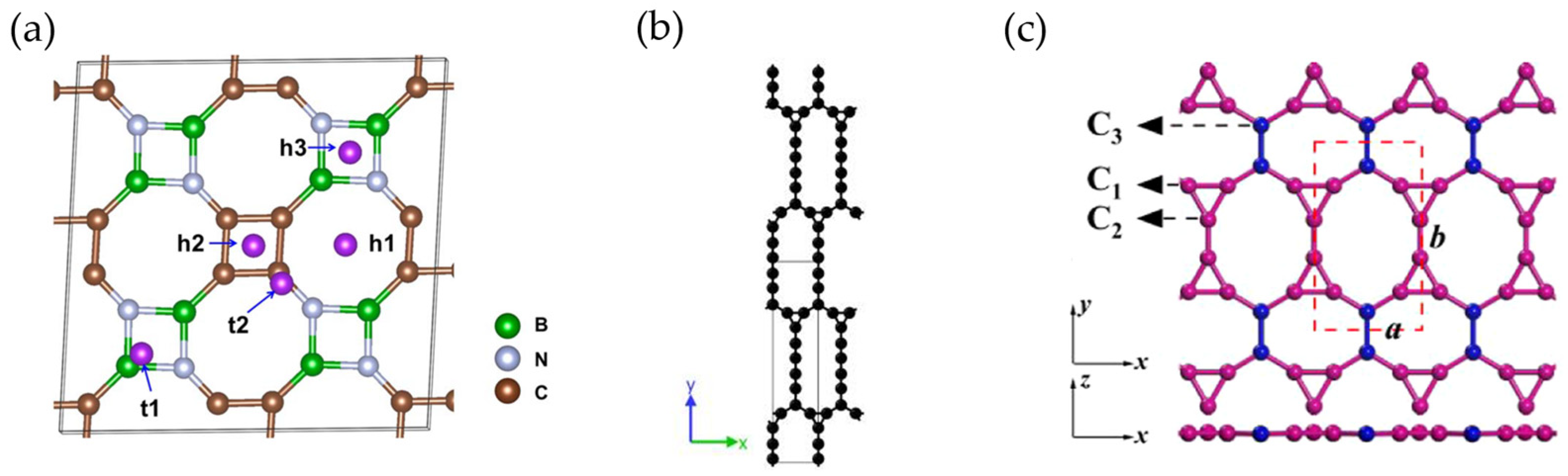
- Luo, Y.; Chen, H.; Wang, J.; Niu, X. Machine-Learning-Assisted Discovery of Boron-Doped Graphene with High Work Function as an Anode Material for Li/Na/K-Ion Batteries. Phys. Chem. Chem. Phys. 2023, 25, 12200–12206. [Google Scholar] [CrossRef] [PubMed]
- Chen, X.; Lin, J.; Li, R.; Lin, Q. Exploring the Potential of T-Graphene-like BC2 N Monolayer as an Anode Material for Na/K-Ion Batteries. Mater. Res. Express 2023, 10, 085007. [Google Scholar] [CrossRef]
- Barman, N.; Sarkar, U. Twin Graphene as an Anode Material for Potassium-ion Battery: A First Principle Study. Energy Storage 2024, 6, e673. [Google Scholar] [CrossRef]
- Yang, T.; Wang, G.-Q.; Dai, Y.-Q.; Zheng, X.-H.; Ye, X.-J.; Liu, C.-S. Two-Dimensional TOD-Graphene in a Honeycomb–Kagome Lattice: A High-Performance Anode Material for Potassium-Ion Batteries. J. Phys. Chem. C 2024, 128, 9413–9421. [Google Scholar] [CrossRef]
- Maździarz, M.; Mrozek, A.; Kuś, W.; Burczyński, T. Anisotropic-Cyclicgraphene: A New Two-Dimensional Semiconducting Carbon Allotrope. Materials 2018, 11, 432. [Google Scholar] [CrossRef]
- Lu, X.; Peng, H.; Liu, G.; Qi, F.; Shi, C.; Wu, S.; Wu, Y.; Yang, H.; Shan, J.; Sun, Z. Hard Carbons: Potential Anode Materials for Potassium Ion Batteries and Their Current Bottleneck. Energy Adv. 2023, 2, 1294–1308. [Google Scholar] [CrossRef]
- Xiao, B.; Rojo, T.; Li, X. Hard Carbon as Sodium-Ion Battery Anodes: Progress and Challenges. ChemSusChem 2019, 12, 133–144. [Google Scholar] [CrossRef] [PubMed]
- Wang, X.; Han, K.; Qin, D.; Li, Q.; Wang, C.; Niu, C.; Mai, L. Polycrystalline Soft Carbon Semi-Hollow Microrods as Anode for Advanced K-Ion Full Batteries. Nanoscale 2017, 9, 18216–18222. [Google Scholar] [CrossRef] [PubMed]
- Liu, Y.; Lu, Y.; Xu, Y.; Meng, Q.; Gao, J.; Sun, Y.; Hu, Y.; Chang, B.; Liu, C.; Cao, A. Pitch-Derived Soft Carbon as Stable Anode Material for Potassium Ion Batteries. Adv. Mater. 2020, 32, 2000505. [Google Scholar] [CrossRef]
- Wu, S.; Song, Y.; Lu, C.; Yang, T.; Yuan, S.; Tian, X.; Liu, Z. High-Rate Soft Carbon Anode in Potassium Ion Batteries: The Role of Chemical Structures of Pitches. Carbon 2023, 203, 211–220. [Google Scholar] [CrossRef]
- Cheng, B.; Li, X.; Pan, L.; Xu, H.; Duan, H.; Wu, Q.; Yin, B.; He, H. Ultra-Thin Wrinkled Carbon Sheet as an Anode Material of High-Power-Density Potassium-Ion Batteries. Molecules 2022, 27, 2973. [Google Scholar] [CrossRef]
- He, X.; Zhong, L.; Qiu, X.; Wen, F.; Sun, S.; Zu, X.; Zhang, W. Sustainable Polyvinyl Chloride-Derived Soft Carbon Anodes for Potassium-Ion Storage: Electrochemical Behaviors and Mechanism. ChemSusChem 2023, 16, e202300646. [Google Scholar] [CrossRef]
- Yao, J.; Liu, C.; Zhu, Y.; Sun, Y.; Feng, D.; Yao, Y.; Mao, Q.; Ma, T. Liquid Phase Oxidation Enables Stable Soft Carbon Anodes for Potassium-Ion Batteries. Carbon Res. 2024, 3, 23. [Google Scholar] [CrossRef]
- Jian, Z.; Xing, Z.; Bommier, C.; Li, Z.; Ji, X. Hard Carbon Microspheres: Potassium-Ion Anode Versus Sodium-Ion Anode. Adv. Energy Mater. 2016, 6, 1501874. [Google Scholar] [CrossRef]
- Alvin, S.; Cahyadi, H.S.; Hwang, J.; Chang, W.; Kwak, S.K.; Kim, J. Revealing the Intercalation Mechanisms of Lithium, Sodium, and Potassium in Hard Carbon. Adv. Energy Mater. 2020, 10, 2000283. [Google Scholar] [CrossRef]
- Vaalma, C.; Giffin, G.A.; Buchholz, D.; Passerini, S. Non-Aqueous K-Ion Battery Based on Layered K 0.3 MnO 2 and Hard Carbon/Carbon Black. J. Electrochem. Soc. 2016, 163, A1295–A1299. [Google Scholar] [CrossRef]
- Tan, L.; Chen, J.; Wang, L.; Li, N.; Yang, Y.; Chen, Y.; Guo, L.; Ji, X.; Zhu, Y. High-Coulombic-Efficiency Hard Carbon Anode Material for Practical Potassium-Ion Batteries. Batter. Supercaps 2024, 7, e202400010. [Google Scholar] [CrossRef]
- Chen, C.; Wang, Z.; Zhang, B.; Miao, L.; Cai, J.; Peng, L.; Huang, Y.; Jiang, J.; Huang, Y.; Zhang, L.; et al. Nitrogen-Rich Hard Carbon as a Highly Durable Anode for High-Power Potassium-Ion Batteries. Energy Storage Mater. 2017, 8, 161–168. [Google Scholar] [CrossRef]
- Yang, H.; Lei, L.; Zhao, Y.; Lan, D.; An, S.; Liu, Y.; Cui, J. Lignite-Based Hard Carbon for High-Performance Potassium-Ion Battery Anode. Ionics 2024, 30, 3253–3263. [Google Scholar] [CrossRef]
- Alvin, S.; Chandra, C.; Kim, J. Extended Plateau Capacity of Phosphorus-Doped Hard Carbon Used as an Anode in Na- and K-Ion Batteries. Chem. Eng. J. 2020, 391, 123576. [Google Scholar] [CrossRef]
- Zhang, Y.; Li, L.; Xiang, Y.; Zou, G.; Hou, H.; Deng, W.; Ji, X. High Sulfur-Doped Hard Carbon with Advanced Potassium Storage Capacity via a Molten Salt Method. ACS Appl. Mater. Interfaces 2020, 12, 30431–30437. [Google Scholar] [CrossRef] [PubMed]
- Yang, J.; Ju, Z.; Jiang, Y.; Xing, Z.; Xi, B.; Feng, J.; Xiong, S. Enhanced Capacity and Rate Capability of Nitrogen/Oxygen Dual-Doped Hard Carbon in Capacitive Potassium-Ion Storage. Adv. Mater. 2018, 30, 1700104. [Google Scholar] [CrossRef] [PubMed]
- Chen, M.; Wang, W.; Liang, X.; Gong, S.; Liu, J.; Wang, Q.; Guo, S.; Yang, H. Sulfur/Oxygen Codoped Porous Hard Carbon Microspheres for High-Performance Potassium-Ion Batteries. Adv. Energy Mater. 2018, 8, 1800171. [Google Scholar] [CrossRef]
- Liu, Y.; Dai, H.; Wu, L.; Zhou, W.; He, L.; Wang, W.; Yan, W.; Huang, Q.; Fu, L.; Wu, Y. A Large Scalable and Low-Cost Sulfur/Nitrogen Dual-Doped Hard Carbon as the Negative Electrode Material for High-Performance Potassium-Ion Batteries. Adv. Energy Mater. 2019, 9, 1901379. [Google Scholar] [CrossRef]
- Xu, H.; Cheng, B.; Du, Q.; Zhang, Y.; Duan, H.; Egun, I.L.; Yin, B.; He, H. Strengthening Synergistic Effects between Hard Carbon and Soft Carbon Enabled by Connecting Precursors at Molecular Level towards High-Performance Potassium Ion Batteries. Nano Res. 2023, 16, 10985–10991. [Google Scholar] [CrossRef]
- Available online: https://www.flickr.com/photos/mrspugliano/5350438637 (accessed on 14 November 2024).
- Yu, D.; Ma, Y.; Hu, F.; Lin, C.; Li, L.; Chen, H.; Han, X.; Peng, S. Dual-Sites Coordination Engineering of Single Atom Catalysts for Flexible Metal–Air Batteries. Adv. Energy Mater. 2021, 11, 2101242. [Google Scholar] [CrossRef]
- Fang, Y.; Gu, D.; Zou, Y.; Wu, Z.; Li, F.; Che, R.; Deng, Y.; Tu, B.; Zhao, D. A Low-Concentration Hydrothermal Synthesis of Biocompatible Ordered Mesoporous Carbon Nanospheres with Tunable and Uniform Size. Angew. Chem. Int. Ed. 2010, 49, 7987–7991. [Google Scholar] [CrossRef]
- Liu, Y.; Fan, F.; Wang, J.; Liu, Y.; Chen, H.; Jungjohann, K.L.; Xu, Y.; Zhu, Y.; Bigio, D.; Zhu, T.; et al. In Situ Transmission Electron Microscopy Study of Electrochemical Sodiation and Potassiation of Carbon Nanofibers. Nano Lett. 2014, 14, 3445–3452. [Google Scholar] [CrossRef] [PubMed]
- Zhao, X.; Xiong, P.; Meng, J.; Liang, Y.; Wang, J.; Xu, Y. High Rate and Long Cycle Life Porous Carbon Nanofiber Paper Anodes for Potassium-Ion Batteries. J. Mater. Chem. A 2017, 5, 19237–19244. [Google Scholar] [CrossRef]
- Adams, R.A.; Syu, J.-M.; Zhao, Y.; Lo, C.-T.; Varma, A.; Pol, V.G. Binder-Free N- and O-Rich Carbon Nanofiber Anodes for Long Cycle Life K-Ion Batteries. ACS Appl. Mater. Interfaces 2017, 9, 17872–17881. [Google Scholar] [CrossRef] [PubMed]
- Hao, R.; Lan, H.; Kuang, C.; Wang, H.; Guo, L. Superior Potassium Storage in Chitin-Derived Natural Nitrogen-Doped Carbon Nanofibers. Carbon 2018, 128, 224–230. [Google Scholar] [CrossRef]
- Xu, Y.; Zhang, C.; Zhou, M.; Fu, Q.; Zhao, C.; Wu, M.; Lei, Y. Highly Nitrogen Doped Carbon Nanofibers with Superior Rate Capability and Cyclability for Potassium Ion Batteries. Nat. Commun. 2018, 9, 1720. [Google Scholar] [CrossRef] [PubMed]
- Wang, Y.; Wang, Z.; Chen, Y.; Zhang, H.; Yousaf, M.; Wu, H.; Zou, M.; Cao, A.; Han, R.P.S. Hyperporous Sponge Interconnected by Hierarchical Carbon Nanotubes as a High-Performance Potassium-Ion Battery Anode. Adv. Mater. 2018, 30, 1802074. [Google Scholar] [CrossRef] [PubMed]
- Wang, B.; Yuan, F.; Wang, W.; Zhang, D.; Sun, H.; Xi, K.; Wang, D.; Chu, J.; Wang, Q.; Li, W. A Carbon Microtube Array with a Multihole Cross Profile: Releasing the Stress and Boosting Long-Cycling and High-Rate Potassium Ion Storage. J. Mater. Chem. A 2019, 7, 25845–25852. [Google Scholar] [CrossRef]
- Liu, Y.; Yang, C.; Pan, Q.; Li, Y.; Wang, G.; Ou, X.; Zheng, F.; Xiong, X.; Liu, M.; Zhang, Q. Nitrogen-Doped Bamboo-like Carbon Nanotubes as Anode Material for High Performance Potassium Ion Batteries. J. Mater. Chem. A 2018, 6, 15162–15169. [Google Scholar] [CrossRef]
- Zhao, X.; Tang, Y.; Ni, C.; Wang, J.; Star, A.; Xu, Y. Free-Standing Nitrogen-Doped Cup-Stacked Carbon Nanotube Mats for Potassium-Ion Battery Anodes. ACS Appl. Energy Mater. 2018, 1, 1703–1707. [Google Scholar] [CrossRef]
- Zeng, S.; Zhou, X.; Wang, B.; Feng, Y.; Xu, R.; Zhang, H.; Peng, S.; Yu, Y. Freestanding CNT-Modified Graphitic Carbon Foam as a Flexible Anode for Potassium Ion Batteries. J. Mater. Chem. A 2019, 7, 15774–15781. [Google Scholar] [CrossRef]
- Khan, N.; Han, G.; Mazari, S.A. Carbon Nanotubes-Based Anode Materials for Potassium Ion Batteries: A Review. J. Electroanal. Chem. 2022, 907, 116051. [Google Scholar] [CrossRef]
- Cao, B.; Zhang, Q.; Liu, H.; Xu, B.; Zhang, S.; Zhou, T.; Mao, J.; Pang, W.K.; Guo, Z.; Li, A.; et al. Graphitic Carbon Nanocage as a Stable and High Power Anode for Potassium-Ion Batteries. Adv. Energy Mater. 2018, 8, 1801149. [Google Scholar] [CrossRef]
- Ding, J.; Zhang, H.; Zhou, H.; Feng, J.; Zheng, X.; Zhong, C.; Paek, E.; Hu, W.; Mitlin, D. Sulfur-Grafted Hollow Carbon Spheres for Potassium-Ion Battery Anodes. Adv. Mater. 2019, 31, 1900429. [Google Scholar] [CrossRef] [PubMed]
- Lu, X.; Liang, Z.; Fang, Z.; Zhang, D.; Zheng, Y.; Liu, Q.; Fu, D.; Teng, J.; Yang, W. Durable K-ion Batteries with 100% Capacity Retention up to 40,000 Cycles. Carbon Energy 2024, 6, e390. [Google Scholar] [CrossRef]
- Wang, W.; Zhou, J.; Wang, Z.; Zhao, L.; Li, P.; Yang, Y.; Yang, C.; Huang, H.; Guo, S. Short-Range Order in Mesoporous Carbon Boosts Potassium-Ion Battery Performance. Adv. Energy Mater. 2018, 8, 1701648. [Google Scholar] [CrossRef]
- Bin, D.-S.; Lin, X.-J.; Sun, Y.-G.; Xu, Y.-S.; Zhang, K.; Cao, A.-M.; Wan, L.-J. Engineering Hollow Carbon Architecture for High-Performance K-Ion Battery Anode. J. Am. Chem. Soc. 2018, 140, 7127–7134. [Google Scholar] [CrossRef] [PubMed]
- Xu, Q.; Li, Q.; Guo, Y.; Luo, D.; Qian, J.; Li, X.; Wang, Y. Multiscale Hierarchically Engineered Carbon Nanosheets Derived from Covalent Organic Framework for Potassium-Ion Batteries. Small Methods 2020, 4, 2000159. [Google Scholar] [CrossRef]
- Du, J.; Gao, S.; Shi, P.; Fan, J.; Xu, Q.; Min, Y. Three-Dimensional Carbonaceous for Potassium Ion Batteries Anode to Boost Rate and Cycle Life Performance. J. Power Sources 2020, 451, 227727. [Google Scholar] [CrossRef]
- Deng, Q.; Zhao, Y.; Zhu, X.; Yang, K.; Li, M. Recent Advances and Challenges in Ti-Based Oxide Anodes for Superior Potassium Storage. Nanomaterials 2023, 13, 2539. [Google Scholar] [CrossRef] [PubMed]
- Li, Y.; Yang, C.; Zheng, F.; Pan, Q.; Liu, Y.; Wang, G.; Liu, T.; Hu, J.; Liu, M. Design of TiO2eC Hierarchical Tubular Heterostructures for High Performance Potassium Ion Batteries. Nano Energy 2019, 59, 582–590. [Google Scholar] [CrossRef]
- Liao, J.; Hu, Q.; Mu, J.; Chen, F.; He, X.; Chen, F.; Wen, Z.; Chen, C. Introducing a Conductive Pillar: A Polyaniline Intercalated Layered Titanate for High-Rate and Ultra-Stable Sodium and Potassium Ion Storage. Chem. Commun. 2020, 56, 8392–8395. [Google Scholar] [CrossRef]
- Cai, J.; Cai, R.; Sun, Z.; Wang, X.; Wei, N.; Xu, F.; Shao, Y.; Gao, P.; Dou, S.; Sun, J. Confining TiO2 Nanotubes in PECVD-Enabled Graphene Capsules Toward Ultrafast K-Ion Storage: In Situ TEM/XRD Study and DFT Analysis. Nano-Micro Lett. 2020, 12, 123. [Google Scholar] [CrossRef] [PubMed]
- Dubal, D.P.; Schneemann, A.; Ranc, V.; Kment, Š.; Tomanec, O.; Petr, M.; Kmentova, H.; Otyepka, M.; Zbořil, R.; Fischer, R.A.; et al. Ultrafine TiO2 Nanoparticle Supported Nitrogen-Rich Graphitic Porous Carbon as an Efficient Anode Material for Potassium-Ion Batteries. Adv. Energy Sustain. Res. 2021, 2, 2100042. [Google Scholar] [CrossRef]
- Ling, L.; Wang, X.; Zhou, M.; Wu, K.; Lin, C.; Younus, H.A.; Zhang, M.; Zhang, S.; Cheng, F.; Zhang, Y. Carbon-Coated Flower-Like TiO2 Nanosphere as an Ultrastable Anode Material for Potassium-Ion Batteries: Structure Design and Mechanism Study. ACS Appl. Energy Mater. 2022, 5, 15586–15596. [Google Scholar] [CrossRef]
- Li, W.; Gao, N.; Cheng, S.; Wu, J.; Chen, Q. Electrochemical Performance of Sandwich-like Structured TiO2/Graphene Composite as Anode for Potassium-Ion Batteries. Int. J. Electrochem. Sci. 2022, 17, 221222. [Google Scholar] [CrossRef]
- Lee, G.-W.; Park, B.H.; Nazarian-Samani, M.; Kim, Y.H.; Roh, K.C.; Kim, K.-B. Magnéli Phase Titanium Oxide as a Novel Anode Material for Potassium-Ion Batteries. ACS Omega 2019, 4, 5304–5309. [Google Scholar] [CrossRef] [PubMed]
- Wu, S.; Feng, Y.; Wu, K.; Jiang, W.; Xue, Z.; Xiong, D.; Chen, L.; Feng, Z.; Wen, K.; Li, Z.; et al. Mxene Ti3C2 Generated TiO2 Nanoparticles in Situ and Uniformly Embedded in rGO Sheets as High Stable Anodes for Potassium Ion Batteries. J. Alloys Compd. 2023, 930, 167414. [Google Scholar] [CrossRef]
- Su, D.; Liu, L.; Liu, Z.; Dai, J.; Wen, J.; Yang, M.; Jamil, S.; Deng, H.; Cao, G.; Wang, X. Electrospun Ta-Doped TiO2/C Nanofibers as a High-Capacity and Long-Cycling Anode Material for Li-Ion and K-Ion Batteries. J. Mater. Chem. A 2020, 8, 20666–20676. [Google Scholar] [CrossRef]
- Cui, J.; Yin, P.; Xu, A.; Jin, B.; Li, Z.; Shao, M. Fluorine Enhanced Nucleophilicity of TiO2 Nanorod Arrays: A General Approach for Dendrite-Free Anodes towards High-Performance Metal Batteries. Nano Energy 2022, 93, 106837. [Google Scholar] [CrossRef]
- Kishore, B.; G, V.; Munichandraiah, N. K2Ti4O9: A Promising Anode Material for Potassium Ion Batteries. J. Electrochem. Soc. 2016, 163, A2551–A2554. [Google Scholar] [CrossRef]
- Dong, Y.; Wu, Z.-S.; Zheng, S.; Wang, X.; Qin, J.; Wang, S.; Shi, X.; Bao, X. Ti3C2 MXene-Derived Sodium/Potassium Titanate Nanoribbons for High-Performance Sodium/Potassium Ion Batteries with Enhanced Capacities. ACS Nano 2017, 11, 4792–4800. [Google Scholar] [CrossRef] [PubMed]
- Han, J.; Xu, M.; Niu, Y.; Li, G.-N.; Wang, M.; Zhang, Y.; Jia, M.; Li, C.M. Exploration of K2Ti8O17 as an Anode Material for Potassium-Ion Batteries. Chem. Commun. 2016, 52, 11274–11276. [Google Scholar] [CrossRef] [PubMed]
- Han, J.; Niu, Y.; Bao, S.; Yu, Y.-N.; Lu, S.-Y.; Xu, M. Nanocubic KTi2(PO4)3 Electrodes for Potassium-Ion Batteries. Chem. Commun. 2016, 52, 11661–11664. [Google Scholar] [CrossRef]
- Liu, S.; Li, X.; Zhong, S.; Jiang, W.; Liu, Y.; Ding, W.; Hu, H.; Huang, Z.; Liu, L. Electrosprayed Hierarchical Mesoporous Mn0.5Ti2(PO4)3@C Microspheres as Promising High-Performance Anode for Potassium-Ion Batteries. J. Colloid Interface Sci. 2024, 658, 923–933. [Google Scholar] [CrossRef] [PubMed]
- Zhang, R.; Huang, J.; Deng, W.; Bao, J.; Pan, Y.; Huang, S.; Sun, C. Safe, Low-Cost, Fast-Kinetics and Low-Strain Inorganic-Open-Framework Anode for Potassium-Ion Batteries. Angew. Chem. 2019, 131, 16626–16631. [Google Scholar] [CrossRef]
- Ramezankhani, V.; Luchinin, N.D.; Marshenya, S.N.; Zakharkin, M.V.; Golubnichiy, A.A.; Morozov, A.V.; Emilianova, O.; Stevenson, K.J.; Antipov, E.V.; Abakumov, A.M.; et al. Exploring KTiPO4F as a Robust Polyanion Anode Material for Potassium-Ion Batteries. J. Mater. Chem. A 2024, 12, 18404–18411. [Google Scholar] [CrossRef]
- Qi, Y.; Li, J.; Zhong, W.; Bao, S.; Xu, M. KTiOPO4: A Long-Life, High-Rate and Low-Temperature-Workable Host for Na/K-Ion Batteries. Chem. Eng. J. 2021, 417, 128159. [Google Scholar] [CrossRef]
- Liu, C.; Wang, H.; Zhang, S.; Han, M.; Cao, Y.; Liu, S.; Yang, Z.; Chen, A.; Sun, J. K2Ti6O13/Carbon Core–Shell Nanorods as a Superior Anode Material for High-Rate Potassium-Ion Batteries. Nanoscale 2020, 12, 11427–11434. [Google Scholar] [CrossRef]
- Chen, M.; Liu, Q.; Hu, Z.; Zhang, Y.; Xing, G.; Tang, Y.; Chou, S. Designing Advanced Vanadium-Based Materials to Achieve Electrochemically Active Multielectron Reactions in Sodium/Potassium-Ion Batteries. Adv. Energy Mater. 2020, 10, 2002244. [Google Scholar] [CrossRef]
- Liu, C.; Luo, S.; Huang, H.; Wang, Z.; Wang, Q.; Zhang, Y.; Liu, Y.; Zhai, Y.; Wang, Z. Potassium Vanadate K0.23V2O5 as Anode Materials for Lithium-Ion and Potassium-Ion Batteries. J. Power Sources 2018, 389, 77–83. [Google Scholar] [CrossRef]
- Jiang, X.; Tian, S.; Jiang, Q.; Xu, C.; Gao, P.; Zhou, T.; Zhou, J. A V2O5-Based Freestanding Anode with High Rate and Superior Cycle Life for Potassium Storage. Compos. Commun. 2022, 32, 101172. [Google Scholar] [CrossRef]
- Lu, J.; Wang, C.; Xia, G.; Tong, H.; Yang, Y.; Zhu, D.; Chen, Q. A Robust Spring-like Lamellar VO/C Nanostructure for High-Rate and Long-Life Potassium-Ion Batteries. J. Mater. Chem. A 2020, 8, 23939–23946. [Google Scholar] [CrossRef]
- Lu, M.; Wang, K.; Ke, H.; Hu, Q.; Liu, Z.; Wu, H. Potassium Vanadate K2V3O8 as a Superior Anode Material for Potassium-Ion Batteries. Mater. Lett. 2018, 232, 224–227. [Google Scholar] [CrossRef]
- Li, Y.; Zhang, Q.; Yuan, Y.; Liu, H.; Yang, C.; Lin, Z.; Lu, J. Surface Amorphization of Vanadium Dioxide (B) for K-Ion Battery. Adv. Energy Mater. 2020, 10, 2000717. [Google Scholar] [CrossRef]
- Kuai, X.; Li, K.; Chen, J.; Wang, H.; Yao, J.; Chiang, C.-L.; Liu, T.; Ye, H.; Zhao, J.; Lin, Y.-G.; et al. Interfacial Engineered Vanadium Oxide Nanoheterostructures Synchronizing High-Energy and Long-Term Potassium-Ion Storage. ACS Nano 2022, 16, 1502–1510. [Google Scholar] [CrossRef] [PubMed]
- Jin, T.; Li, H.; Li, Y.; Jiao, L.; Chen, J. Intercalation Pseudocapacitance in Flexible and Self-Standing V2O3 Porous Nanofibers for High-Rate and Ultra-Stable K Ion Storage. Nano Energy 2018, 50, 462–467. [Google Scholar] [CrossRef]
- Chen, F.; Wang, S.; He, X.-D.; Liao, J.-Y.; Hu, Q.; Dong, J.-M.; Chen, C.-H. Hollow Sphere Structured V2 O3@C as an Anode Material for High Capacity Potassium-Ion Batteries. J. Mater. Chem. A 2020, 8, 13261–13266. [Google Scholar] [CrossRef]
- Hu, J.; Xie, Y.; Zheng, J.; Li, H.; Wang, T.; Lai, Y.; Zhang, Z. Encapsulating V2O3 Nanoparticles in Hierarchical Porous Carbon Nanosheets via C–O–V Bonds for Fast and Durable Potassium-Ion Storage. ACS Appl. Mater. Interfaces 2021, 13, 12149–12158. [Google Scholar] [CrossRef] [PubMed]
- Coetzee, D.; Militký, J.; Wiener, J.; Venkataraman, M. Comparison of the Synthesis, Properties, and Applications of Graphite. In Advanced Multifunctional Materials from Fibrous Structures; Militký, J., Venkataraman, M., Eds.; Advanced Structured Materials; Springer Nature: Singapore, 2023; Volume 201, ISBN 978-981-99-6001-9. [Google Scholar]
- Zhao, L.; Hu, Z.; Lai, W.; Tao, Y.; Peng, J.; Miao, Z.; Wang, Y.; Chou, S.; Liu, H.; Dou, S. Hard Carbon Anodes: Fundamental Understanding and Commercial Perspectives for Na-Ion Batteries beyond Li-Ion and K-Ion Counterparts. Adv. Energy Mater. 2021, 11, 2002704. [Google Scholar] [CrossRef]
- Zhang, S.; Yin, Z.; Wang, L.; Shu, M.; Liang, X.; Liang, S.; Hu, L.; Deng, C.; Hu, K.; Zhu, X. Interlayer Expansion and Conductive Networking of MoS2 Nanoroses Mediated by Bio-Derived Carbon for Enhanced Potassium-Ion Storage. Energy Mater. 2024, 4, 400065. [Google Scholar] [CrossRef]
- Nason, C.A.F.; Vijaya Kumar Saroja, A.P.; Lu, Y.; Wei, R.; Han, Y.; Xu, Y. Layered Potassium Titanium Niobate/Reduced Graphene Oxide Nanocomposite as a Potassium-Ion Battery Anode. Nano-Micro Lett. 2024, 16, 1. [Google Scholar] [CrossRef]
- Fong, R.; Von Sacken, U.; Dahn, J.R. Studies of Lithium Intercalation into Carbons Using Nonaqueous Electrochemical Cells. J. Electrochem. Soc. 1990, 137, 2009–2013. [Google Scholar] [CrossRef]
- Li, K.; Zhang, J.; Lin, D.; Wang, D.-W.; Li, B.; Lv, W.; Sun, S.; He, Y.-B.; Kang, F.; Yang, Q.-H.; et al. Evolution of the Electrochemical Interface in Sodium Ion Batteries with Ether Electrolytes. Nat. Commun. 2019, 10, 725. [Google Scholar] [CrossRef] [PubMed]
- Qin, B.; Zarrabeitia, M.; Hoefling, A.; Jusys, Z.; Liu, X.; Tübke, J.; Behm, R.J.; Cui, G.; Varzi, A.; Passerini, S. A Unique Polymer-Inorganic Cathode-Electrolyte-Interphase (CEI) Boosts High-Performance Na3V2(PO4)2F3 Batteries in Ether Electrolytes. J. Power Sources 2023, 560, 232630. [Google Scholar] [CrossRef]
- Ando, H.; Hashi, K.; Ohki, S.; Hatakeyama, Y.; Nishina, Y.; Kowata, N.; Ohkubo, T.; Gotoh, K. State Change of Na Clusters in Hard Carbon Electrodes and Increased Capacity for Na-Ion Batteries Achieved by Heteroatom Doping. Carbon Trends 2024, 16, 100387. [Google Scholar] [CrossRef]


| Cyclability | Rate Capability | |||||||
|---|---|---|---|---|---|---|---|---|
| Anode Material | Electrolyte | Binder | ICE | Initial Capacity (mAh g−1)@ Current Density (A g−1) | Capacity (mAh g−1) | Cycle Number@ Current Density (A g−1) | Capacity (mAh g−1)@ Current Density (A g−1) | Ref. |
| SC | 0.8 M KPF6/EC:DEC | PVDF | ~78% | ~273@0.007 | ~163 | 50 cycles@0.56 | 140@1.4 | [32] |
| SC hollow microrods | 0.8 M KPF6/EC:DMC + 5 wt.% FEC | PTFE | ~57% | ~340@0.1 | 249 | 100 cycles@0.1 | 214@0.5 | [110] |
| Pitch-derived SC | 0.8 M KPF6/EC:DEC | CMC+SBR | ~53% | 296@0.028 200@0.28 | 276 183 | 50 cycles@0.028 1000 cycles@0.28 | 115@1.4 | [111] |
| USC | 0.8 M KPF6/EC:DEC | CMC | N/A | ~1200@0.025 1080@0.1 | 280 137 | 50 cycles@0.025 2500 cycles@1 | 151@6.4 | [113] |
| PVC-SC-800 | 0.8 M KPF6/EC:DEC | CMC | 68.3% | ~300@0.1 | 200 | 50 cycles@0.1 | 92@2 | [114] |
| ONC-SC | 0.8 M KPF6/EC:DEC | PVDF | 55.7% | ~323@0.05 | 106 | 500 cycles@1 | 99@2 | [115] |
| HC microspheres | 0.8 M KPF6/EC:DEC | PVDF | 61.8% | 262@0.028 | 216 | 100 cycles@0.028 | 136@1.4 | [116] |
| CS-HC | 2.5 M KFSI/TEP | CMC | 87.3% | 288@0.05 280@0.3 | 267 214 | 100 cycles@0.5 500 cycles@0.3 | 280@0.3 | [119] |
| N-doped CS (chitin) | 0.8 M KPF6/EC:DEC | PVDF | ~88% | 180@0.5 | 180 | 4000 cycles@0.5 | 154@20.2 | [120] |
| N-doped HC (lignite) | 1 M KPF6/EC:DEC | CMC | 41.5% | 392@0.1 N/A 1 | 314 125 | 100 cycles@0.1 1500 cycles@1 | 118@2 | [121] |
| P-doped HC | 0.8 M KPF6/EC:DEC | PVDF | N/A | 160 | ~155 | 700 cycles@0.3 | ~175@0.5 | [122] |
| S-doped HC | 0.8 M KPF6/EC:DEC | CMC | 35.1% | 361@0.05 | 318 | 100 cycles@0.05 | 116@1.6 | [123] |
| N/O-doped HC | 1 M KPF6/EC:DEC | PVDF | 25% | 315@0.05 174@1.05 | 230 130 | 100 cycles@0.5 1100 cycles@1.05 | 118@3 | [124] |
| S/O-doped HCMs 2 | 0.8 M KPF6/EC:DEC | PVDF | N/A | 220@0.2 ~175@1 | ~200 ~110 | 200 cycles@0.2 2000 cycles@1 | ~175@1 | [125] |
| S/N-doped HC | 1 M KPF6/EC:DEC | PVDF | ~35% | 294@0.1 174@3 | 235 145 | 300 cycles@0.1 1200 cycles@3 | 174@3 | [126] |
| HC/SC | 0.8 M KPF6/EC:DEC | PVDF | N/A | N/A 1 ~166@1 | 185 101 | 100 cycles@0.1 500 cycles@1 | 121@3.2 | [127] |
| Cyclability | Rate Capability | |||||||
|---|---|---|---|---|---|---|---|---|
| Anode Material | Electrolyte | Binder | ICE | Initial Capacity (mAh g−1)@ Current Density (A g−1) | Capacity (mAh g−1) | Cycle Number@ Current Density (A g−1) | Capacity (mAh g−1)@ Current Density (A g−1) | Ref. |
| K0.23V2O5 | 0.8 M KPF6/EC:DEC | PVDF | 49.3% | 404@0.02 ~265@0.1 | 122 97 | 150 cycles@0.02 100 cycles0.1 | 92@0.4 | [170] |
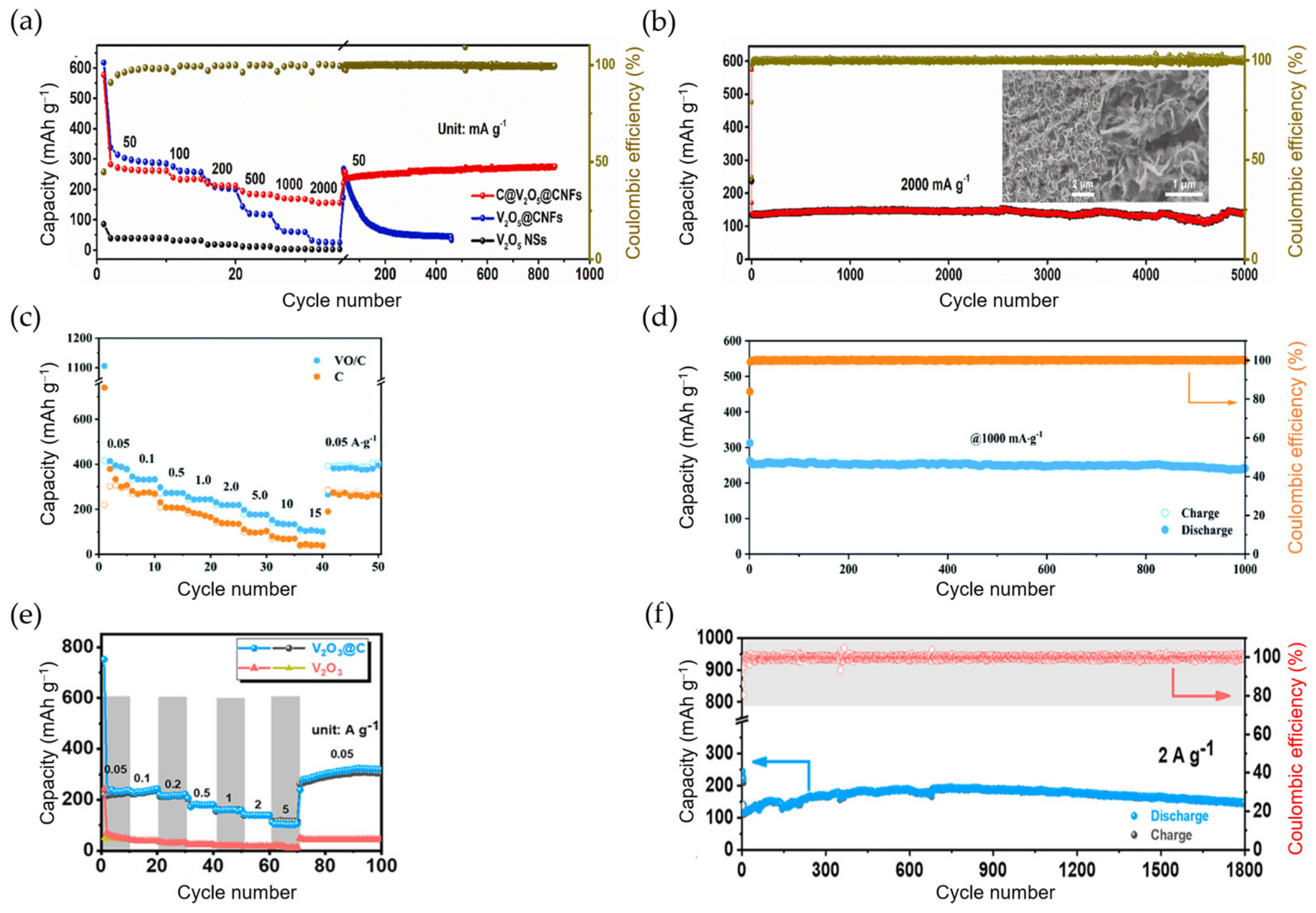
| S-s. C@V2O5@CNFs 1 | 1 M KFS/EC:DMC | Free | 44.9% | 259@0.05 156@2 | 279 139 | 800 cycles@0.05 5000 cycles@2 | 156@2 | [171] |
| VO@C | 1 M KFS/EC:DEC | PVDF | 35.5% | 340@0.1 275@1 | 345 241 | 400 cycles@0.1 1000 cycles@1 | 136@10 | [172] |
| K2V3O8 | 0.8 M KPF6/EC:DMC | CMC | ~60% | 282@0.05 | 84 | 180 cycles@0.1 | 103@0.5 | [173] |
| SA-VO2 | 0.8 M KFSI/EC:DEC | PVDF | 64.4% | 290@0.05 205@0.5 | 288 177 | 50 cycles@0.05 500 cycles@0.5 | 141@2 | [174] |
| VO2-V2O5/NC | 0.8 M KPF6/EC:DMC:DEC | PVDF | N/A | N/A@0.1 ~540@1 | 501 256 | 120 cycles@0.1 1600 cycles@1 | 108@10 | [175] |
| S-s. V2O3 NPs@PNCNFs 1 | 0.8 M KPF6/EC:DEC | Free | 60% | 215@0.05 | 206 | 500 cycles@0.05 | 134@1 | [176] |
| HS-V2O3@C | 3 M KFSI/DME | CMC | 50.9% | ~320@0.1 | 330 | 500 cycles@0.1 | 79@5 | [177] |
| V2O3 NPs@C nanosheets | 1 M KFSI/DME | PVDF | 31% | ~254@0.1 N/A@2 | 267 148 | 100 cycles@0.1 1800 cycles@2 | 116@5 | [178] |
Disclaimer/Publisher’s Note: The statements, opinions and data contained in all publications are solely those of the individual author(s) and contributor(s) and not of MDPI and/or the editor(s). MDPI and/or the editor(s) disclaim responsibility for any injury to people or property resulting from any ideas, methods, instructions or products referred to in the content. |
© 2025 by the authors. Licensee MDPI, Basel, Switzerland. This article is an open access article distributed under the terms and conditions of the Creative Commons Attribution (CC BY) license (https://creativecommons.org/licenses/by/4.0/).
Share and Cite
Piernas-Muñoz, M.J.; Zarrabeitia, M. Revisiting Intercalation Anode Materials for Potassium-Ion Batteries. Materials 2025, 18, 190. https://doi.org/10.3390/ma18010190
Piernas-Muñoz MJ, Zarrabeitia M. Revisiting Intercalation Anode Materials for Potassium-Ion Batteries. Materials. 2025; 18(1):190. https://doi.org/10.3390/ma18010190
Chicago/Turabian StylePiernas-Muñoz, María José, and Maider Zarrabeitia. 2025. "Revisiting Intercalation Anode Materials for Potassium-Ion Batteries" Materials 18, no. 1: 190. https://doi.org/10.3390/ma18010190
APA StylePiernas-Muñoz, M. J., & Zarrabeitia, M. (2025). Revisiting Intercalation Anode Materials for Potassium-Ion Batteries. Materials, 18(1), 190. https://doi.org/10.3390/ma18010190