
Numerical Study to Evaluate the Flexural Performance of Concrete Beams Tensile Reinforced with Fe-Based Shape Memory Alloy Rebar According to Heating Temperature
Abstract
:1. Introduction
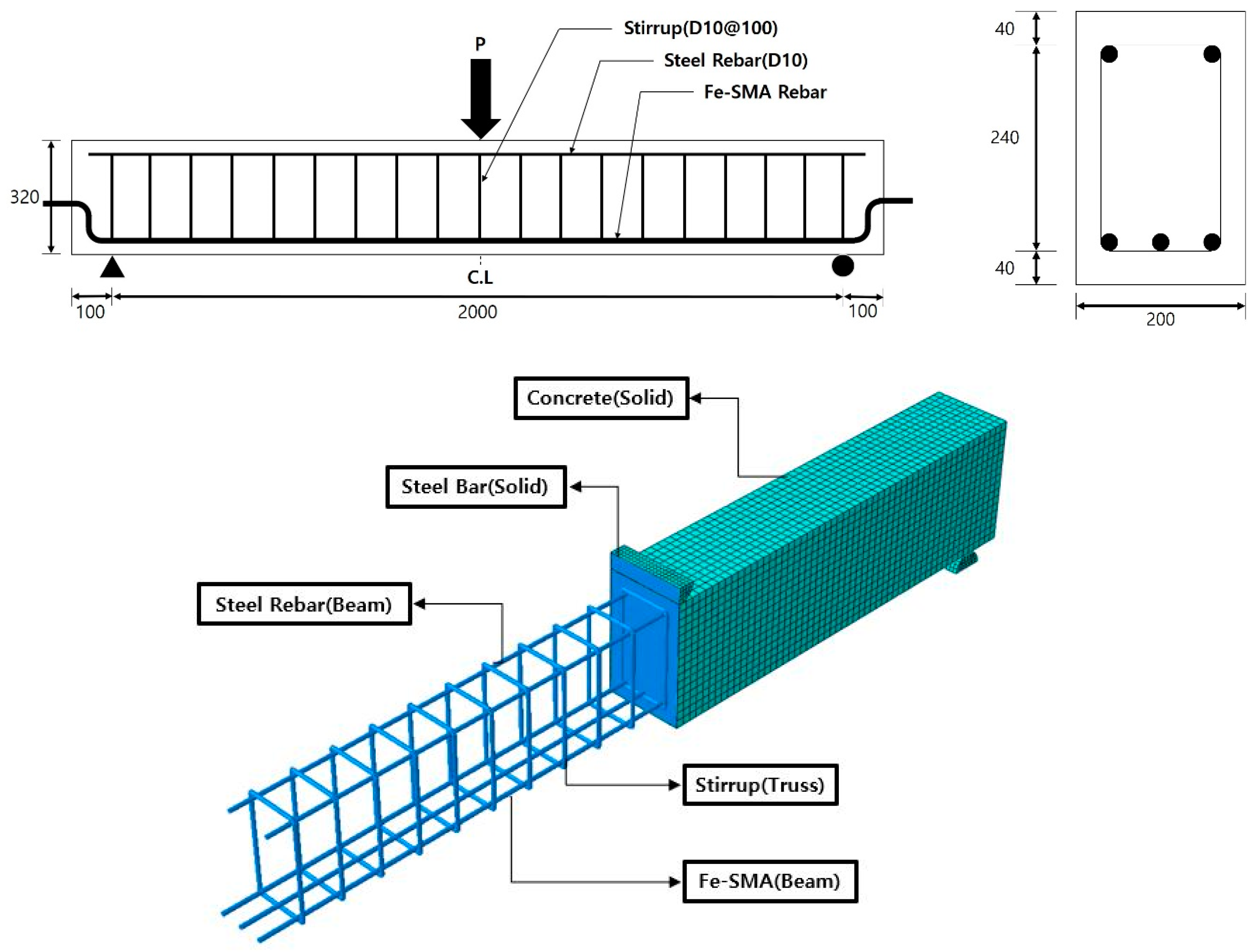
2. Finite Element (FE) Analysis Model
2.1. FE Model (FEM)
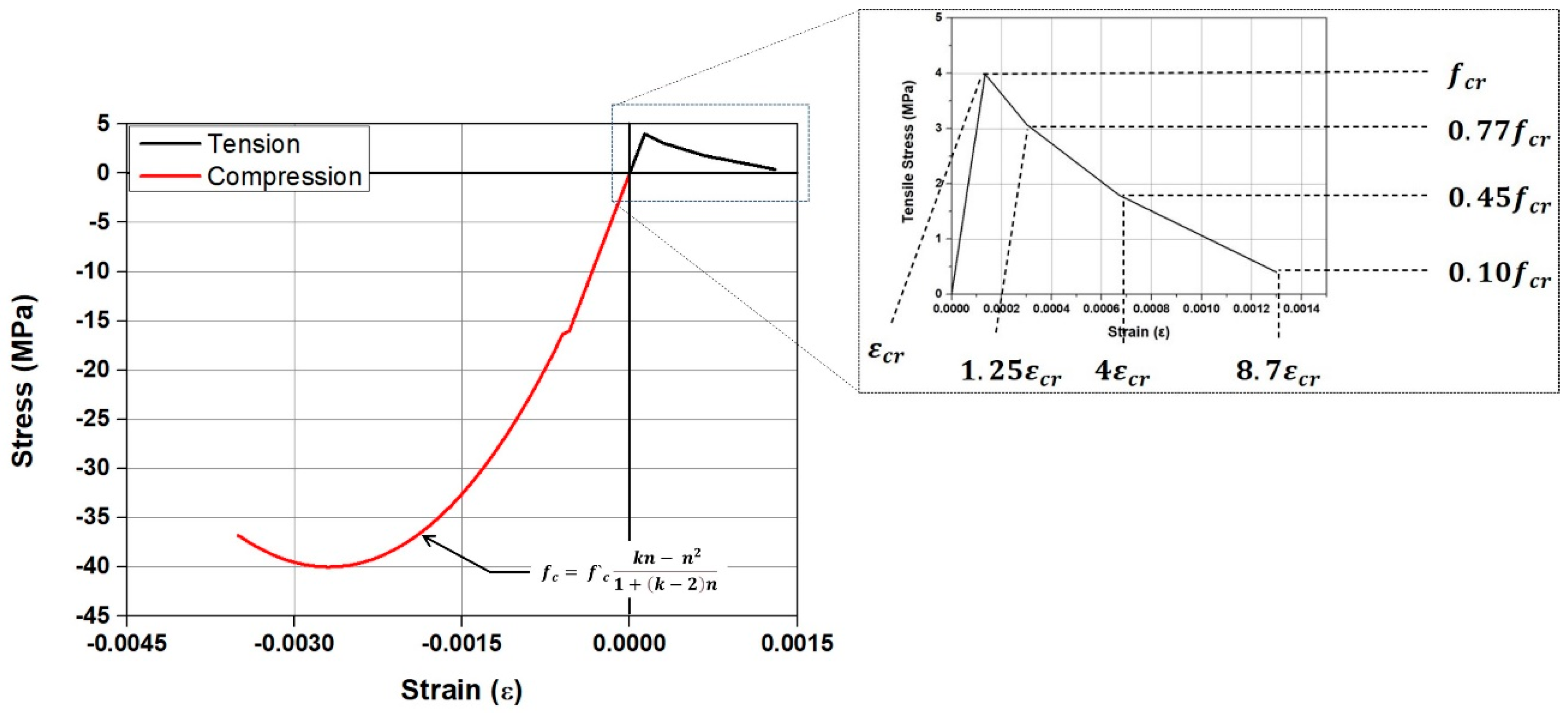
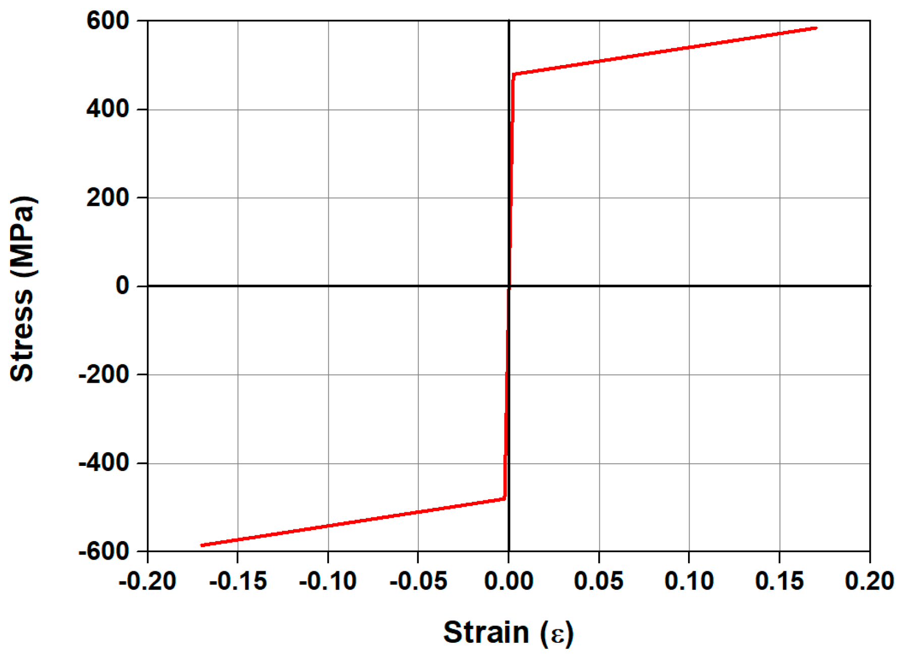
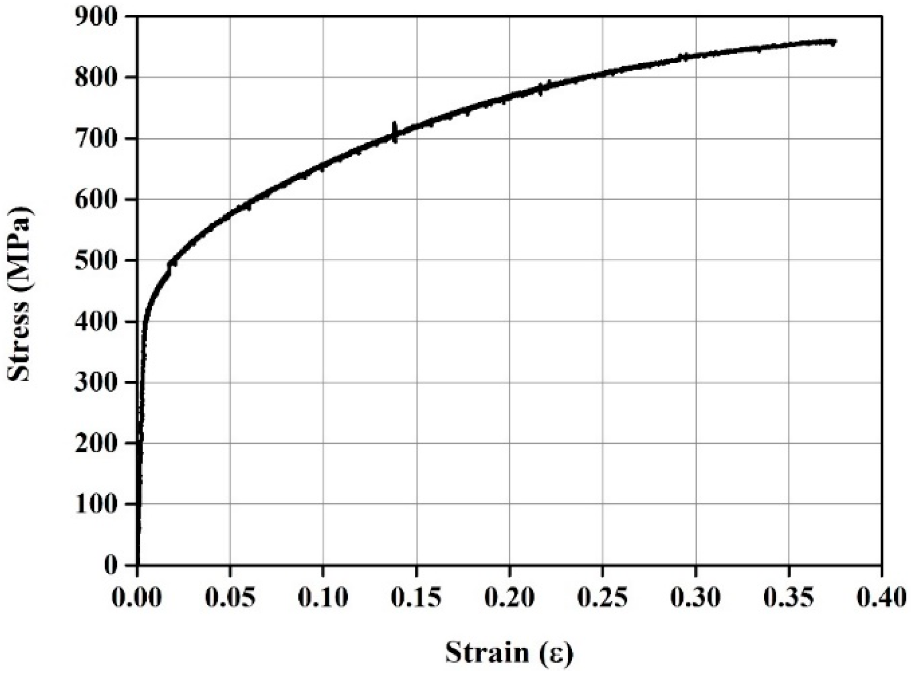
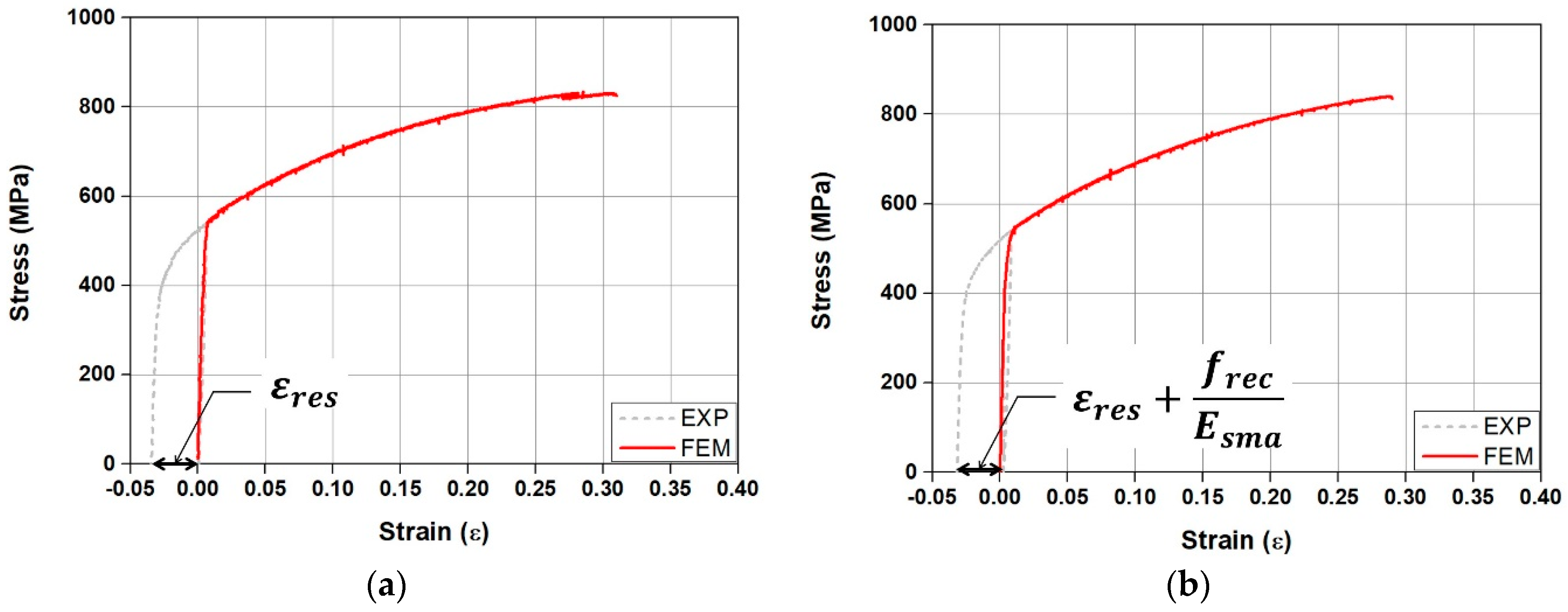
2.2. Material Modeling
3. FE Analysis Results
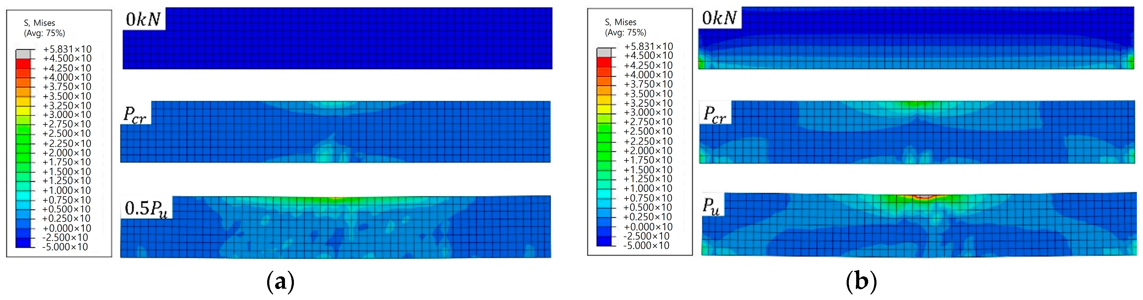
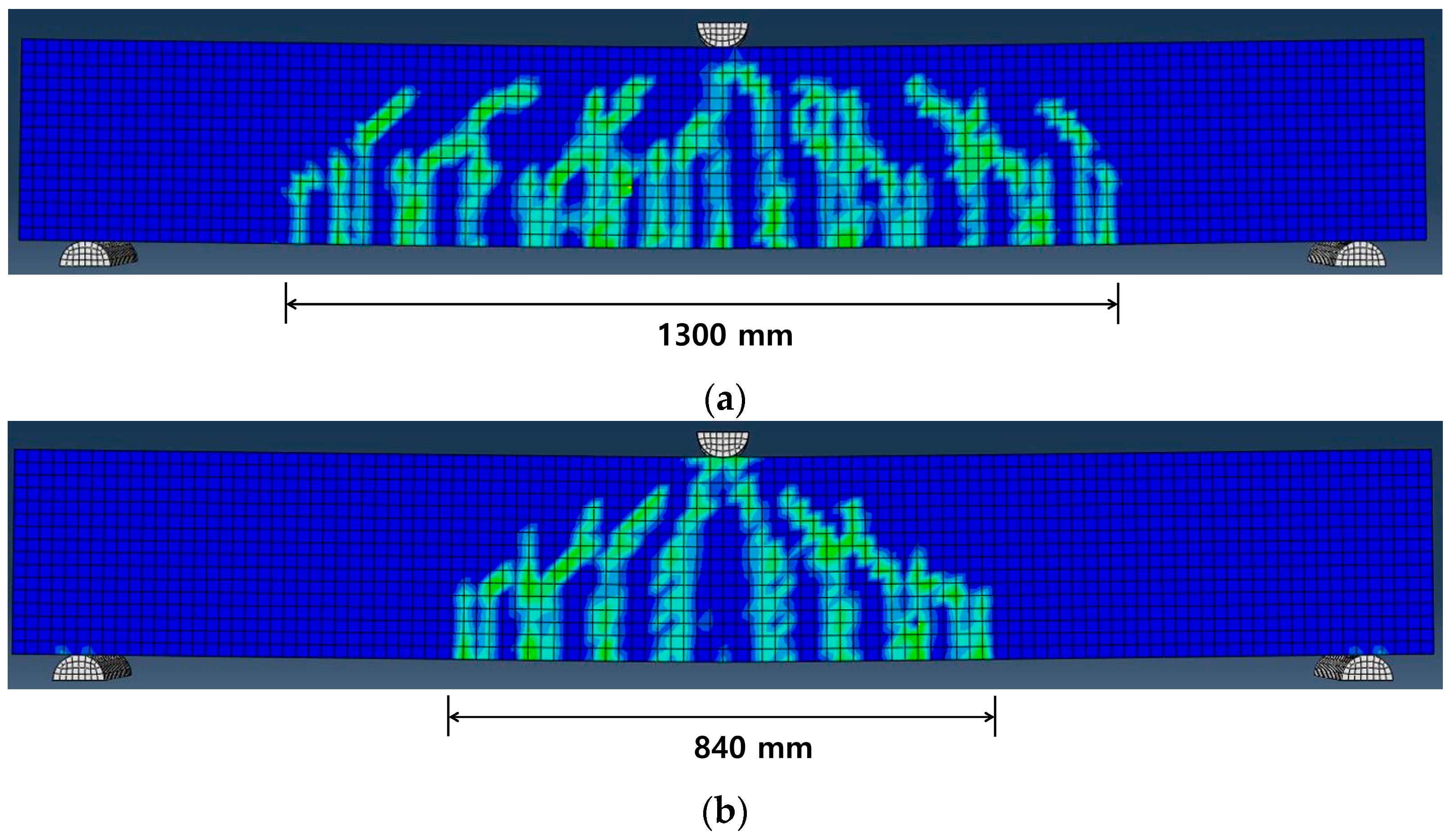
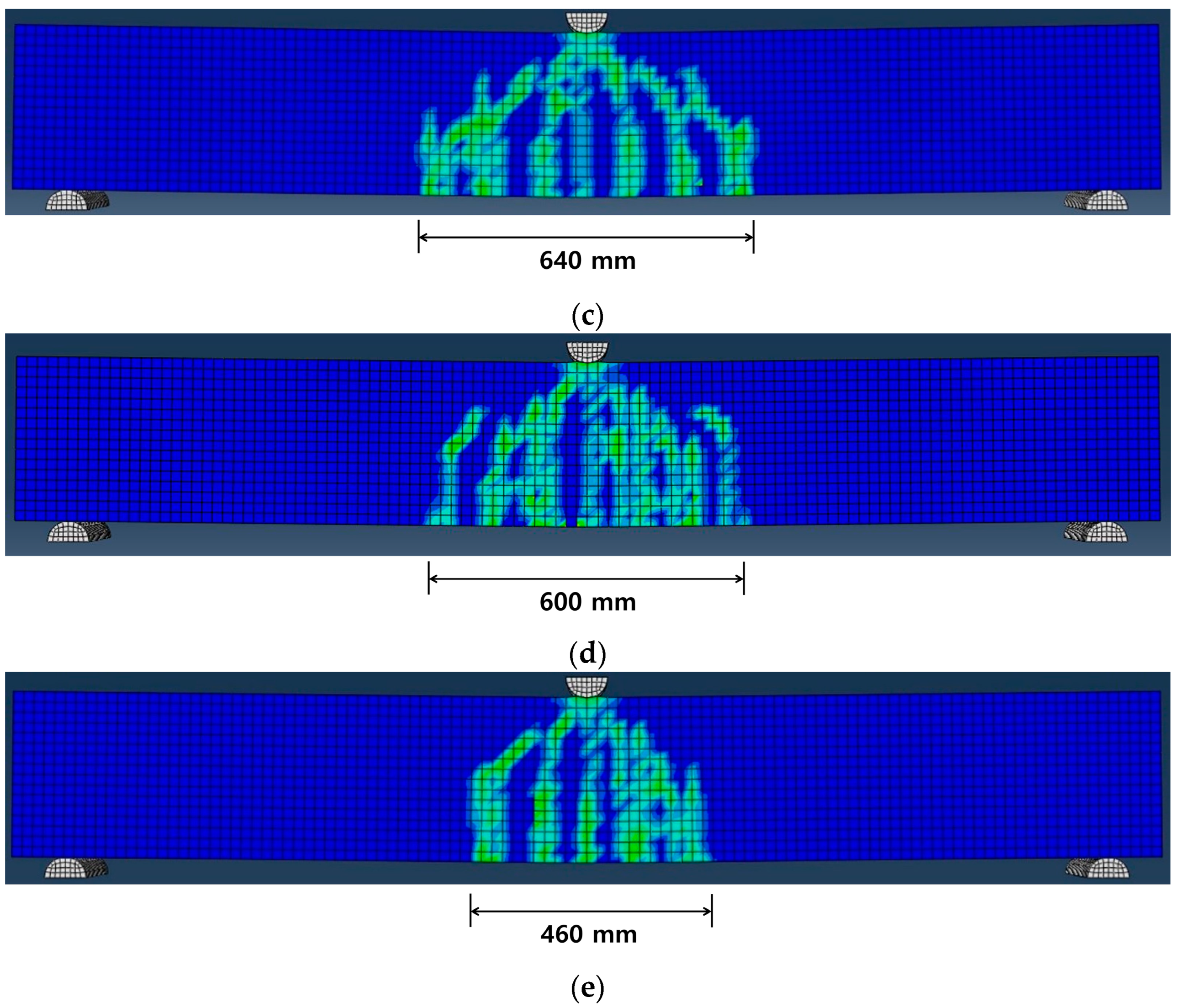
3.1. Failure Mode Predicted by FEM
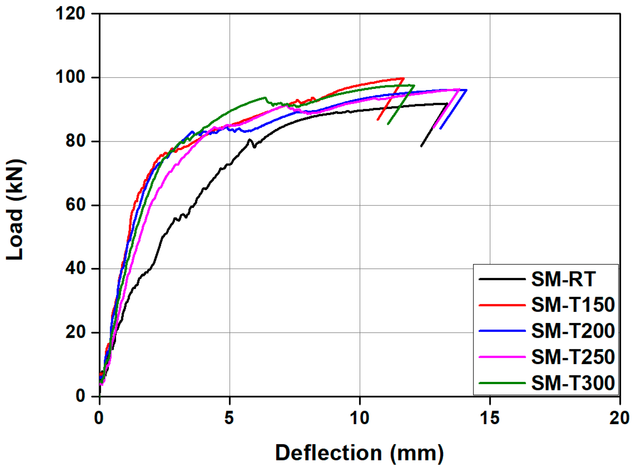
3.2. Load-Carrying Capacity Predicted by FEM
4. Experimental Program for FEM Validation
4.1. Test Specimens
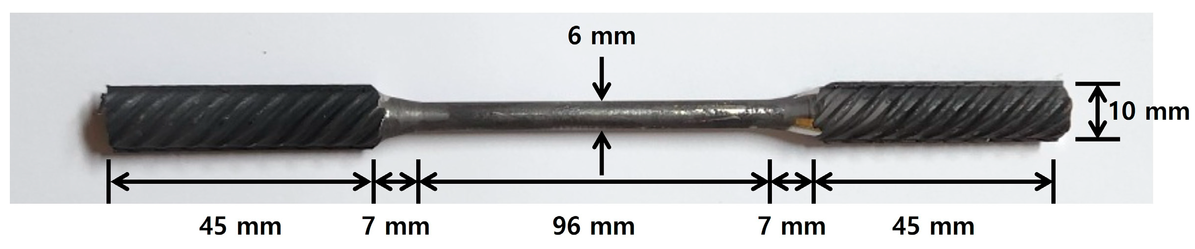
4.2. Materials
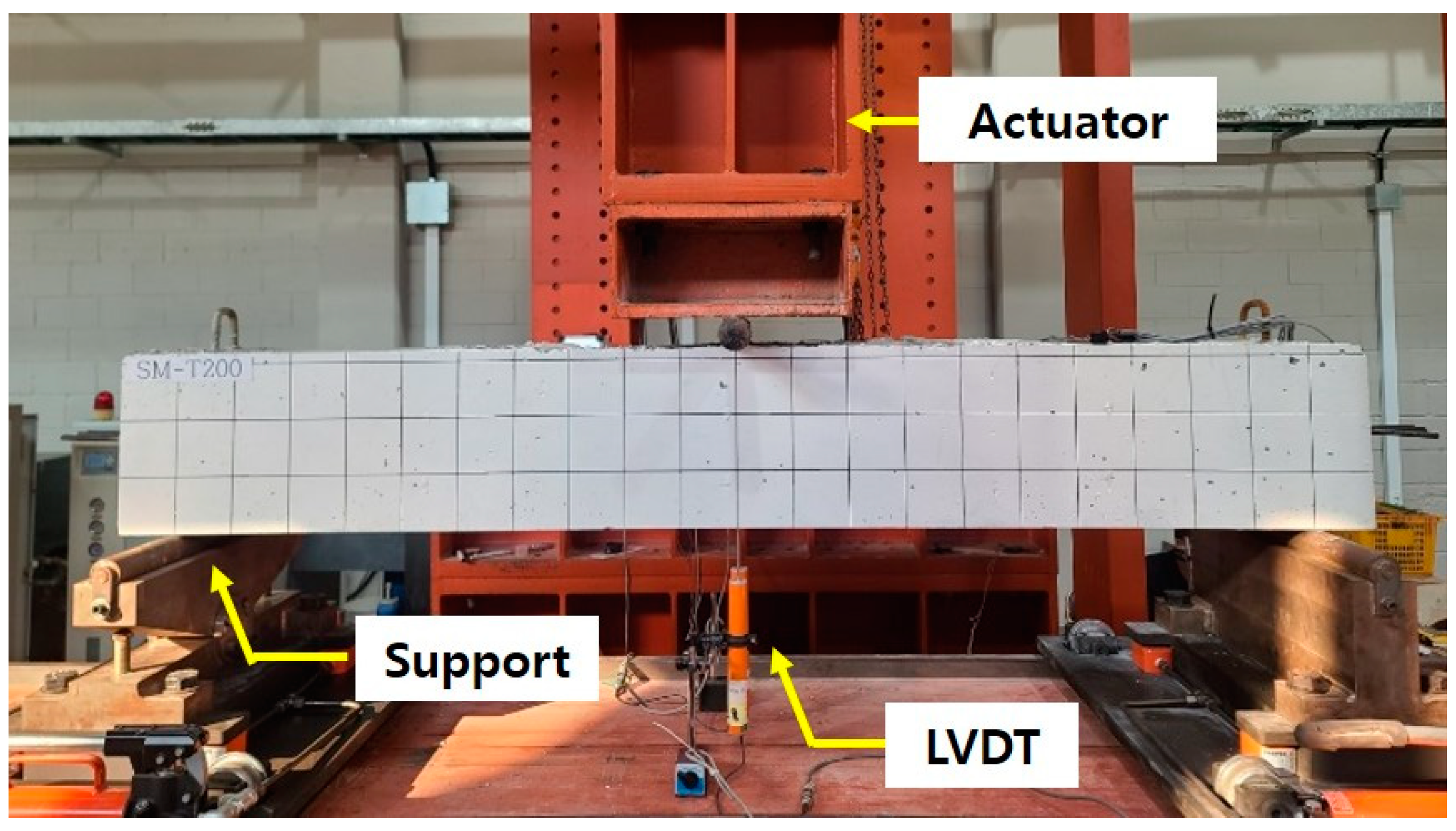
4.3. Test Setup
5. Comparison of Experimental and Numerical Results
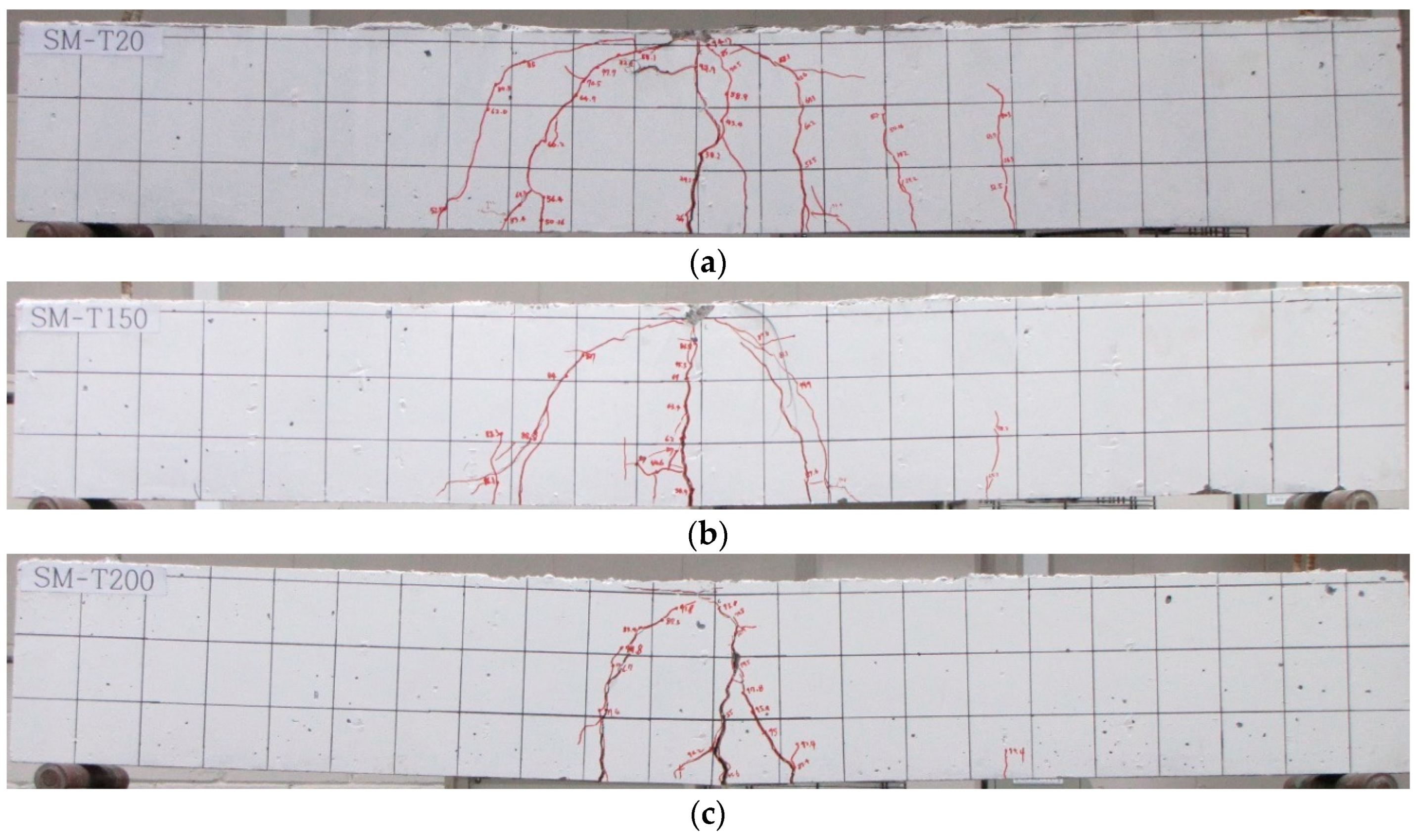
5.1. Failure Mode
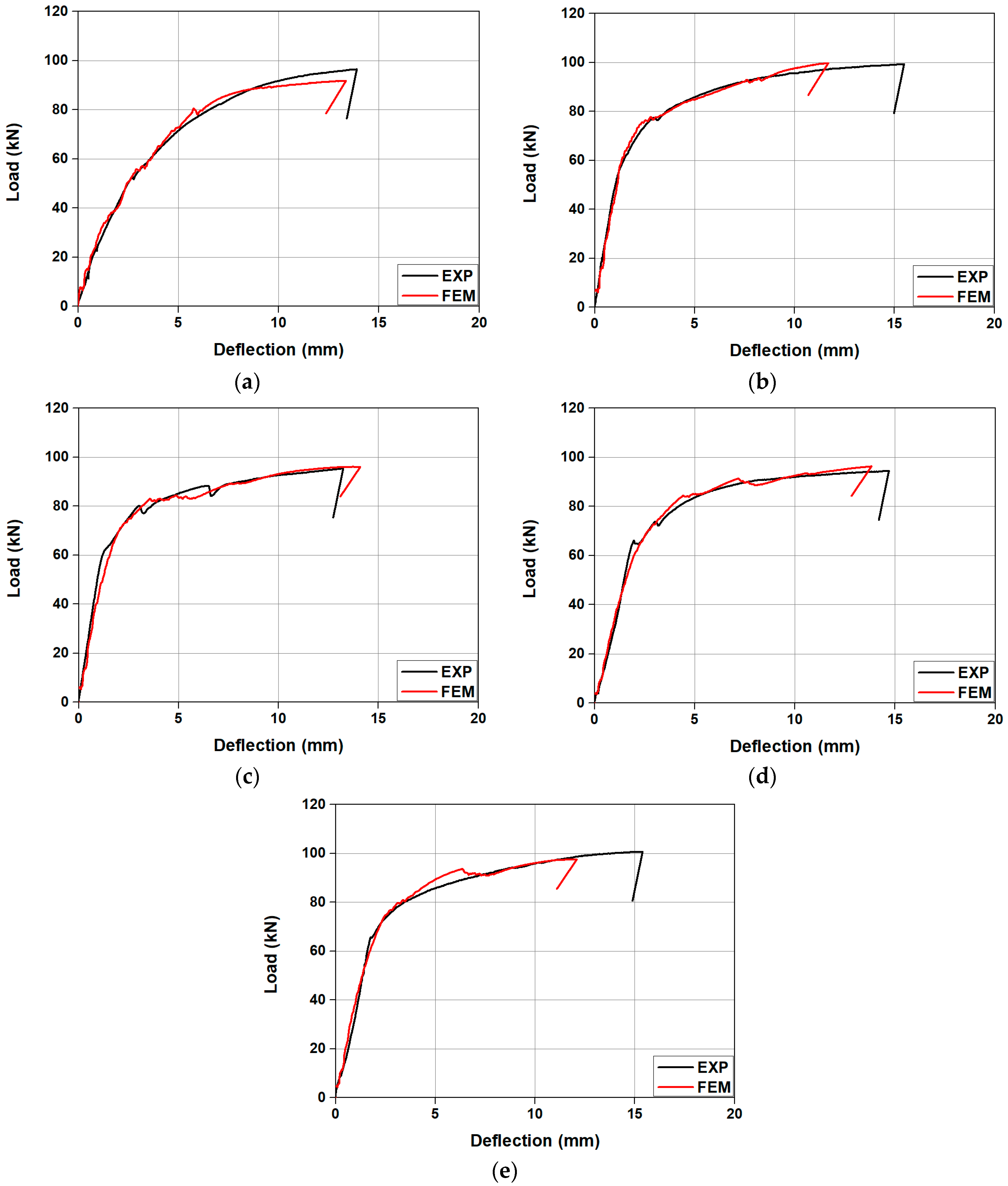
5.2. Load-Carrying Capacity
6. Conclusions
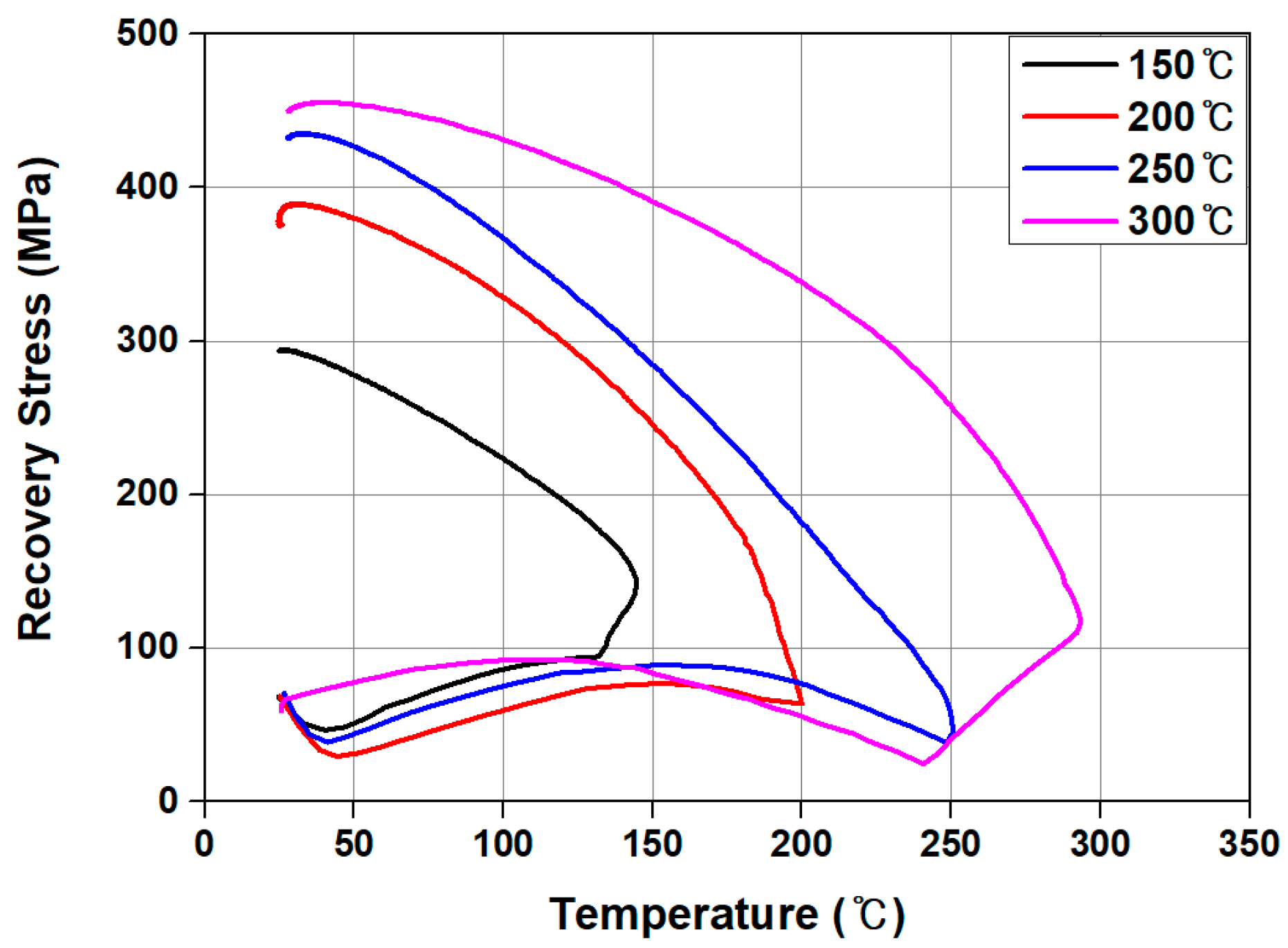
- As a result of experimentally evaluating the recovery stress of Fe-SMA according to the heating temperature, the recovery stress of Fe-SMA heated to 150 °C, ~300 °C was 296 MPa~455 MPa, and the recovery stress increased as the heating temperature increased.
- As a result of FE analysis, as the heating temperature of Fe-SMA increased, the number of cracks generated in the specimen decreased and the cracks were concentrated in the center of the specimen. This decrease in the number of cracks is believed to be the result of Fe-SMA developing a higher recovery stress when the heating temperature increased, introducing a greater prestress force into the specimen.
- The initial crack load of the specimen with activated Fe-SMA showed an increase ranging from 89.7% to 173.2% in comparison to that of the specimen with non-activated Fe-SMA, and this increase was observed to be proportional to the heating temperature. Furthermore, in the final failure stage, both the number of cracks and the width of crack distribution decreased as the heating temperature of Fe-SMA increased.
- Experimental results to verify the accuracy of the proposed FE analysis model; a decrease in the number of cracks and centralization of cracks were observed as the Fe-SMA heating temperature increased, as predicted in FE analysis.
- The initial crack loads observed in the experiments showed a small discrepancy from the values predicted by the FEM, ranging from a minimum of 2% to a maximum of 11%, with an average error of 6.05%. Similarly, the ultimate loads predicted by the FEM exhibited only a minor difference from the experimental results, ranging from 0.4% to 5%, with an average error of 2.2%. Moreover, the load–deflection responses from the FE analysis were found to be in good agreement with the experimental results. Therefore, it is anticipated that the proposed FE analysis model will be capable of accurately predicting the flexural behavior of concrete beams that are tensile reinforced with Fe-SMA rebars.
Author Contributions
Funding
Institutional Review Board Statement
Informed Consent Statement
Data Availability Statement
Conflicts of Interest
Abbreviations
| Fe-SMA | Fe-based shape memory alloy |
| FE | finite element |
| FEM | finite element model |
| NSM | near-surface mounted |
| CFRP | carbon fiber reinforced polymer |
| CDP | Concrete Damaged Plasticity |
| UTM | universal testing machine |
| DAQ | data acquisition system |
References
- Collins, M.P.; Mitchell, D. Prestressed Concrete Structures; Prentice-Hall: Hoboken, NJ, USA, 1991. [Google Scholar]
- Lee, D.-K.; Han, S.-J.; Joo, H.-E.; Kim, K.-S. Control of tensile stress in prestressed concrete members under service loads. Int. J. Concr. Struct. Mater. 2017, 12, 425–437. [Google Scholar]
- De Silva, S.; Mutsuyoshi, H.; Witchukreangkrai, E. Evaluation of shear crack width in I-shaped prestressed reinforced concrete beams. J. Adv. Concr. Technol. 2008, 6, 443–458. [Google Scholar]
- Laursen, P.; Wight, G.; Ingham, J. Assessing creep and shrinkage losses in post-tensioned concrete masonry. ACI Mater. J. 2006, 103, 427. [Google Scholar]
- Lundqvist, P.; Nilsson, L.O. Evaluation of prestress losses in nuclear reactor containments. Nucl. Eng. Des. 2011, 241, 168–176. [Google Scholar] [CrossRef]
- Sawaguchi, T.; Kikuchi, T.; Ogawa, K.; Kajiwara, S.; Ikeo, Y.; Kojima, M.; Ogawa, T. Development of Prestressed Concrete using Fe-Mn-Si-based Shape Memory Alloys Containing NbC. Mater. Trans. 2006, 47, 580–583. [Google Scholar]
- Suhail, R.; Amato, G.; McCrum, D. Thermo-Mechanical Characterisation of NiTi-Based Shape Memory Alloy Wires for Civil Enginnering Applications. J. Intell. Mater. Syst. Struct. 2021, 32, 2420–2436. [Google Scholar] [CrossRef]
- Li, L.; Wang, W.; Chatzi, E.; Ghafoori, E. Experimental investigation on debonding behavior of Fe-SMA-to-steel joints. Constr. Build. Mater. 2023, 364, 129857. [Google Scholar]
- Fritsch, E.; Izadi, M.; Ghafoori, E. Development of nail-anchor strengthening system with iron-based shape memory alloy (Fe-SMA) strips. Constr. Build. Mater. 2019, 229, 117042. [Google Scholar] [CrossRef]
- Janke, L.; Czaderski, C.; Motavalli, M.; Ruth, J. Application of Shape Memory Alloys in Civil Engineering Structures-Overview. Mater. Struct. 2005, 38, 578–592. [Google Scholar]
- Zhang, Z.-X.; Zhang, J.; Wu, H.; Ji, Y.; Kumar, D.D. Iron-based shape memory alloys in construction: Research, applications and opportunities. Materials 2022, 15, 1723. [Google Scholar] [CrossRef]
- Khalil, A.; Elkafrawy, M.; Abuzaid, W.; Hawileh, R.; AlHamaydeh, M. Flexural Performance of RC Beams Strengthened with Pre-Stressed Iron-Based Shape Memory Alloy (Fe-SMA) Bars: Numerical Study. Buildings 2022, 12, 2228. [Google Scholar] [CrossRef]
- Lee, W.-J.; Webe, B.; Czaderski, C.; Motacalli, M.; Leinebach, C. Phase Transformation Behavior Under Uniaxial Deformation of an Fe-Mn-Si-Cr-Ni-VC Shape Memory Alloy. Mater. Sci. Eng. A 2013, 581, 1–7. [Google Scholar]
- Fawaz, G.; Murcia-Delso, J. Bond Behavior of Iron-Based Shape Memory Alloy Reinforcing Bars Embedded in Concrete. Mater. Struct. 2020, 53, 114. [Google Scholar] [CrossRef]
- Buehler, W.J.; Gilfrich, J.V.; Wiley, R.C. Effect of Low Temperature Phase Changes on the Mechanical Properties of Alloys Near Composition TiNi. J. Appl. Phys. 1963, 34, 1475–1477. [Google Scholar] [CrossRef]
- Van Humbeeck, J. Non-medical applications of shape memory alloys. Mater. Sci. Eng. A 1999, 273, 134–148. [Google Scholar] [CrossRef]
- Chaudhari, R.; Vora, J.J.; Parikh, D.M. A Review on Applications of Nitinol Shape Memory Alloy. Recent Adv. Mech. Infrastruct. 2021, 123–132. [Google Scholar]
- Auricchio, F.; Scalet, G.; Urbano, M. A Numerical/Experimental Study of Nitinol Actuator. J. Mater. Eng. Perform. 2014, 23, 2420–2428. [Google Scholar] [CrossRef]
- Rojob, H.; El-Hacha, R. Self-Prestressing Using Iron-Based Shape Memory Alloy for Flexural Strengthening of Reinforced Concrete Beams. ACI Struct. J. 2017, 114, 523–532. [Google Scholar]
- Cladera, A.; Weber, B.; Leinenbach, C.; Czaderski, C.; Shahverdi, M.; Motavalli, M. Iron-based shape memory alloys for civil engineering structures: An overview. Constr. Build. Mater. 2014, 63, 281–293. [Google Scholar] [CrossRef]
- Lee, W.; Weber, B.; Leinenbach, C. Recovery stress formation in a restrained Fe–Mn–Si-based shape memory alloy used for prestressing or mechanical joining. Constr. Build. Mater. 2015, 95, 600–610. [Google Scholar] [CrossRef]
- Zhang, W.; Wen, Y.-H.; Li, N.; Huang, S.-K. Remarkable improvement of recovery stress of Fe–Mn–Si shape memory alloy fabricated by equal channel angular pressing. Mater. Sci. Eng. A 2007, 454–455, 19–23. [Google Scholar]
- Shahverdi, M.; Czaderski, C.; Motavalli, M. Iron-Based Shape Memory Alloys for Prestressed Near-Surface Mounted Strengthening of Reinforced Concrete Beams. Constr. Build. Mater. 2016, 112, 28–38. [Google Scholar]
- Yeon, Y.-M.; Hong, K.-N.; Ji, S.-W. Flexural Behavior of Self-Prestressed RC Slabs with Fe-Based Shape Memory Alloy Rebar. Appl. Sci. 2022, 12, 1640. [Google Scholar] [CrossRef]
- Choi, E.; Ostadrahimi, A.; Kim, W.J.; Seo, J. Prestressing effect of embedded Fe-based SMA wire on the flexural behavior of mortar beams. Eng. Struct. 2021, 227, 111472. [Google Scholar]
- Shahverdi, M.; Michels, J.; Czaderski, C.; Motavalli, M. Iron-Based Shape Memory Alloy Strips for Strengthening RC Members: Material Behavior and Characterization. Constr. Build. Mater. 2018, 173, 586–599. [Google Scholar]
- Chen, Z.Y.; Gu, X.L.; Vollmer, M.; Niendorf, T.; Ghafoori, E.; Yu, Q.Q. Recovery stress behavior of Fe-SMA under fatigue and thermal loading. Thin-Walled Struct. 2023, 188, 110799. [Google Scholar]
- Kim, D.-H.; Park, C.-H.; Lee, J.-H.; Hong, K.-N.; Park, Y.-H.; Lee, W.-J. Microstructure Shape Memory Behavior and Mechanical Properties of Hot Rolled Fe-17Mn-5Si-5Cr-4Ni-0.3C-1Ti Shape Memory Alloy. Eng. Struct. 2021, 236, 112300. [Google Scholar]
- Hong, K.-N.; Yeon, Y.-M.; Shim, W.-B.; Ji, S.-W. Fatigue Characteristic of Fe-based Shape Memory Alloy. Appl. Sci. 2020, 10, 5812. [Google Scholar] [CrossRef]
- Abouali, S.; Shahverdi, M.; Ghassemieh, M.; Motavalli, M. Nonlinear Simulation of Reinforced Concrete Beams Retrofitted by Near Surface Mounted Iron Based Shape Memory Alloy. Eng. Struct. 2019, 187, 133–148. [Google Scholar]
- Yeon, Y.-M.; Hong, K.-N.; Lee, S.; Ji, S.-W. Numerical Study of RC Beams Strengthened with Fe-Based Shape Memory Alloy Strips Using the NSM Method. Appl. Sci. 2021, 11, 6809. [Google Scholar] [CrossRef]
- Rogowski, J.; Kotynia, R. Comparison of prestressing methods with CFRP and SMA materials in flexurally strengthened RC members. Materials 2022, 15, 1231. [Google Scholar] [CrossRef]
- Rezapour, M.; Ghassemieh, M.; Motavalli, M.; Shahverdi, M. Numerical modeling of unreinforced masonry walls strengthened with Fe-based shape memory alloy strips. Materials 2021, 14, 2961. [Google Scholar] [CrossRef] [PubMed]
- Qiang, X.; Chen, L.; Jiang, X. Achievements and perspectives on Fe-based shape memory alloys for rehabilitation of reinforced concrete bridges: An overview. Materials 2022, 15, 8089. [Google Scholar] [CrossRef] [PubMed]
- Hong, K.-N.; Yeon, Y.-M.; Ji, S.-W.; Lee, S. Flexural Behavior of RC Beams Using Fe-Based Shape Memory Alloy Rebars as Tensile Reinforcement. Buildings 2022, 12, 190. [Google Scholar] [CrossRef]
- Ji, S.-W.; Yeon, Y.-M.; Hong, K.-N. Shear Performance of RC Beams Reinforced with Fe-Based Shape Memory Alloy Stirrups. Materials 2022, 15, 1703. [Google Scholar] [CrossRef] [PubMed]
- Zerbe, L.; Vieira, D.; Belarbi, A.; Senouci, A. Uniaxial Compressive Behavior of Circular Concrete Columns Actively Confined with Fe-SMA Strips. Eng. Struct. 2022, 255, 113878. [Google Scholar]
- Jeong, S.; Jung, D. Hysteretic Behavior Evaluation of Reinforced Concrete Columns Retrofitted with Iron-based Shape Memory Alloy Strips. J. Comput. Struct. Eng. Inst. Korea 2022, 35, 287–297. [Google Scholar]
- Hong, K.N.; Lee, S.G.; Han, S.H.; Yeon, Y.M. Evaluation of Fe-Based Shape Memory Alloy (Fe-SMA) as Strengthening Material for Reinforced Concrete Structures. Appl. Sci. 2018, 8, 730. [Google Scholar] [CrossRef]
- Czaderski, C.; Shahverdi, M.; Brönnimann, R.; Leinenbach, C.; Motavalli, M. Feasibility of Iron-Based Shape Memory Alloy Strips for Prestressed Strengthening of Concrete Structures. Constr. Build. Mater. 2014, 56, 94–105. [Google Scholar]
- Gu, X.-L.; Chen, Z.-Y.; Yu, Q.-Q.; Ghafoori, E. Stress recovery behavior of an Fe-Mn-Si shape memory alloy. Eng. Struct. 2021, 243, 112710. [Google Scholar]
- Hong, K.-N.; Yeon, Y.-M.; Shim, W.-B.; Kim, D.-H. Recovery behavior of fe-based shape memory alloys under different restraints. Appl. Sci. 2020, 10, 3441. [Google Scholar] [CrossRef]
- Dassault Systems Simulia Corporation. ABAQUS Analysis User’s Manual 6.10-EF; Dassault Systems Simulia Corporation: Providence, RI, USA, 2010. [Google Scholar]
- Hamah-Ali, B.H.S.; Qadir, M.R.A. The effect of different levels of pre-damage loading on the strength and structural behavior of CFRP strengthened RC beams: Experimental and analytical investigation. PLoS ONE 2021, 16, e0261290. [Google Scholar] [CrossRef] [PubMed]
- Wahalathantri, B.L.; Thambiratnam, D.P.; Chan, T.H.T.; Fawzia, S. A Material Model for Flexural Crack Simulation in Reinforced Concrete Elements Using ABAQUS; Queenslan University of Technology: Brisbane City, Australia, 2011; pp. 260–264. [Google Scholar]
- Kim, D.; Kim, T.; Ji, C.; Ji, S.; Lee, W.; Kim, W. Microstructure and Shape Memory Properties of Gas Tungsten Arc Welded Fe-17Mn-5Si-10Cr-4Ni-(V, C) Shape Memory Alloy. Materials 2024, 17, 4547. [Google Scholar] [CrossRef] [PubMed]
- Lee, W.J.; Partovi-Nia, R.; Suter, T.; Leinenbach, C. Electrochemical Characterization and Corrosion Behavior of an Fe-Mn-Si Shape Memory Alloy in Simulated Concrete Pore Solutions. Mater. Corros. 2015, 67, 839–846. [Google Scholar] [CrossRef]
- Hosseini, E.; Ghafoori, E.; Leinenbach, C.; Motavalli, M.; Holdsworth, S.R. Stress Recovery and Cyclic Behaviour of an Fe–Mn–Si Shape Memory Alloy After Multiple Thermal Activation. Smart Mater. Struct. 2018, 27, 025009. [Google Scholar] [CrossRef]
- ASTM C39/C39M-17b; Standard Test Method for Compressive Strength of Cylindrical Concrete Specimens. ASTM International: West Conshohocken, PA, USA, 2017.


| Specimen | Tensile Reinforcement | Reinforce Ratio (%) | Heating Temperature (°C) |
|---|---|---|---|
| SM-RT | Fe-SMA rebar | 0.482 | - |
| SM-T150 | 150 | ||
| SM-T200 | 200 | ||
| SM-T250 | 250 | ||
| SM-T300 | 300 |
| Dilation Angle | Eccentricity | fb0/fc0 | K | Viscosity Parameter |
|---|---|---|---|---|
| 40 | 0.1 | 1.16 | 0.6667 | 0 |
| Specimen | Initial Crack Load | Ultimate Load | Load Increase Compared to SM-RT (%) | |||
|---|---|---|---|---|---|---|
| Load (kN) | Deflection (mm) | Load (kN) | Deflection (mm) | Initial Crack (%) | Ultimate (%) | |
| SM-RT | 26.63 | 0.93 | 91.83 | 13.36 | - | - |
| SM-T150 | 46.57 | 1.05 | 99.71 | 11.76 | 74.9 | 8.58 |
| SM-T200 | 60.47 | 1.56 | 96.13 | 14.20 | 127.1 | 4.68 |
| SM-T250 | 66.49 | 2.41 | 96.31 | 13.94 | 149.7 | 4.88 |
| SM-T300 | 73.76 | 2.41 | 97.56 | 11.89 | 177.0 | 6.24 |
| Slump (cm) | Air Content (%) | W/B (%) | S/a (%) | Weight Per Unit Volume (kg/m3) | ||||
|---|---|---|---|---|---|---|---|---|
| W | C | S | G | AD | ||||
| 15 | 3.5 | 31.5 | 43.5 | 163 | 361 | 716 | 954 | 4.38 |
| Specimen | Initial Crack Load (kN) | EXP/FEM | Ultimate Load (kN) | EXP/FEM | ||
|---|---|---|---|---|---|---|
| EXP | FEM | EXP | FEM | |||
| SM-T20 | 24.06 | 26.63 | 0.9 | 96.5 | 91.83 | 1.05 |
| SM-T150 | 45.66 | 46.57 | 0.98 | 99.3 | 99.71 | 1.00 |
| SM-T200 | 59.56 | 60.47 | 0.98 | 95.4 | 96.13 | 0.99 |
| SM-T250 | 64 | 66.49 | 0.96 | 94.44 | 96.31 | 0.98 |
| SM-T300 | 65.74 | 73.76 | 0.89 | 100.68 | 97.56 | 1.03 |
| Average | 0.94 | 1.01 | ||||
Disclaimer/Publisher’s Note: The statements, opinions and data contained in all publications are solely those of the individual author(s) and contributor(s) and not of MDPI and/or the editor(s). MDPI and/or the editor(s) disclaim responsibility for any injury to people or property resulting from any ideas, methods, instructions or products referred to in the content. |
© 2025 by the authors. Licensee MDPI, Basel, Switzerland. This article is an open access article distributed under the terms and conditions of the Creative Commons Attribution (CC BY) license (https://creativecommons.org/licenses/by/4.0/).
Share and Cite
Hong, K.-N.; Ji, S.-W.; Yeon, Y.-M. Numerical Study to Evaluate the Flexural Performance of Concrete Beams Tensile Reinforced with Fe-Based Shape Memory Alloy Rebar According to Heating Temperature. Materials 2025, 18, 1703. https://doi.org/10.3390/ma18081703
Hong K-N, Ji S-W, Yeon Y-M. Numerical Study to Evaluate the Flexural Performance of Concrete Beams Tensile Reinforced with Fe-Based Shape Memory Alloy Rebar According to Heating Temperature. Materials. 2025; 18(8):1703. https://doi.org/10.3390/ma18081703
Chicago/Turabian StyleHong, Ki-Nam, Sang-Won Ji, and Yeong-Mo Yeon. 2025. "Numerical Study to Evaluate the Flexural Performance of Concrete Beams Tensile Reinforced with Fe-Based Shape Memory Alloy Rebar According to Heating Temperature" Materials 18, no. 8: 1703. https://doi.org/10.3390/ma18081703
APA StyleHong, K.-N., Ji, S.-W., & Yeon, Y.-M. (2025). Numerical Study to Evaluate the Flexural Performance of Concrete Beams Tensile Reinforced with Fe-Based Shape Memory Alloy Rebar According to Heating Temperature. Materials, 18(8), 1703. https://doi.org/10.3390/ma18081703