
Hot Corrosion Behavior and Damage Mechanism on Yield Property of Nickel-Based Superalloy

 , ,
, ,
Abstract
:1. Introduction
2. Materials and Methods
3. Results
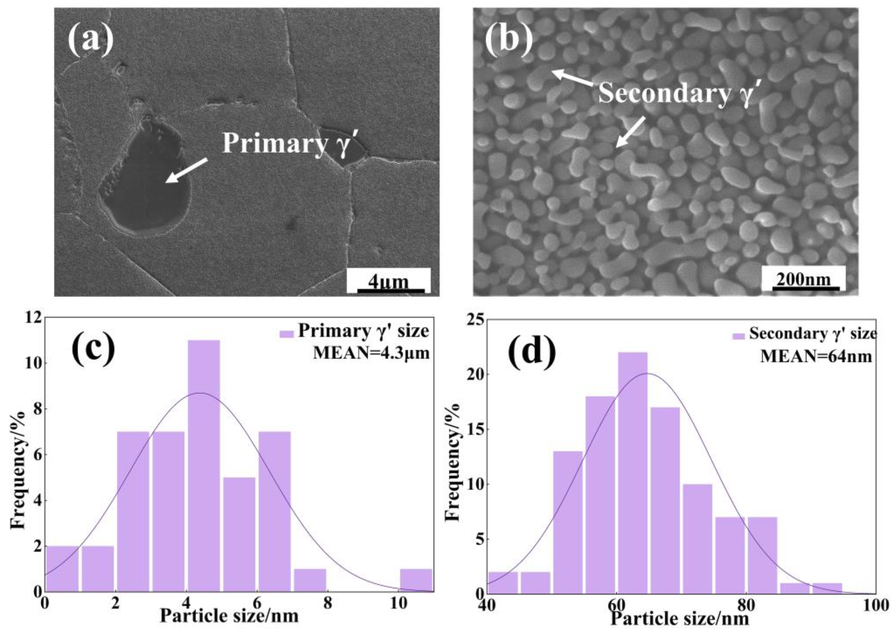
3.1. Microstructure
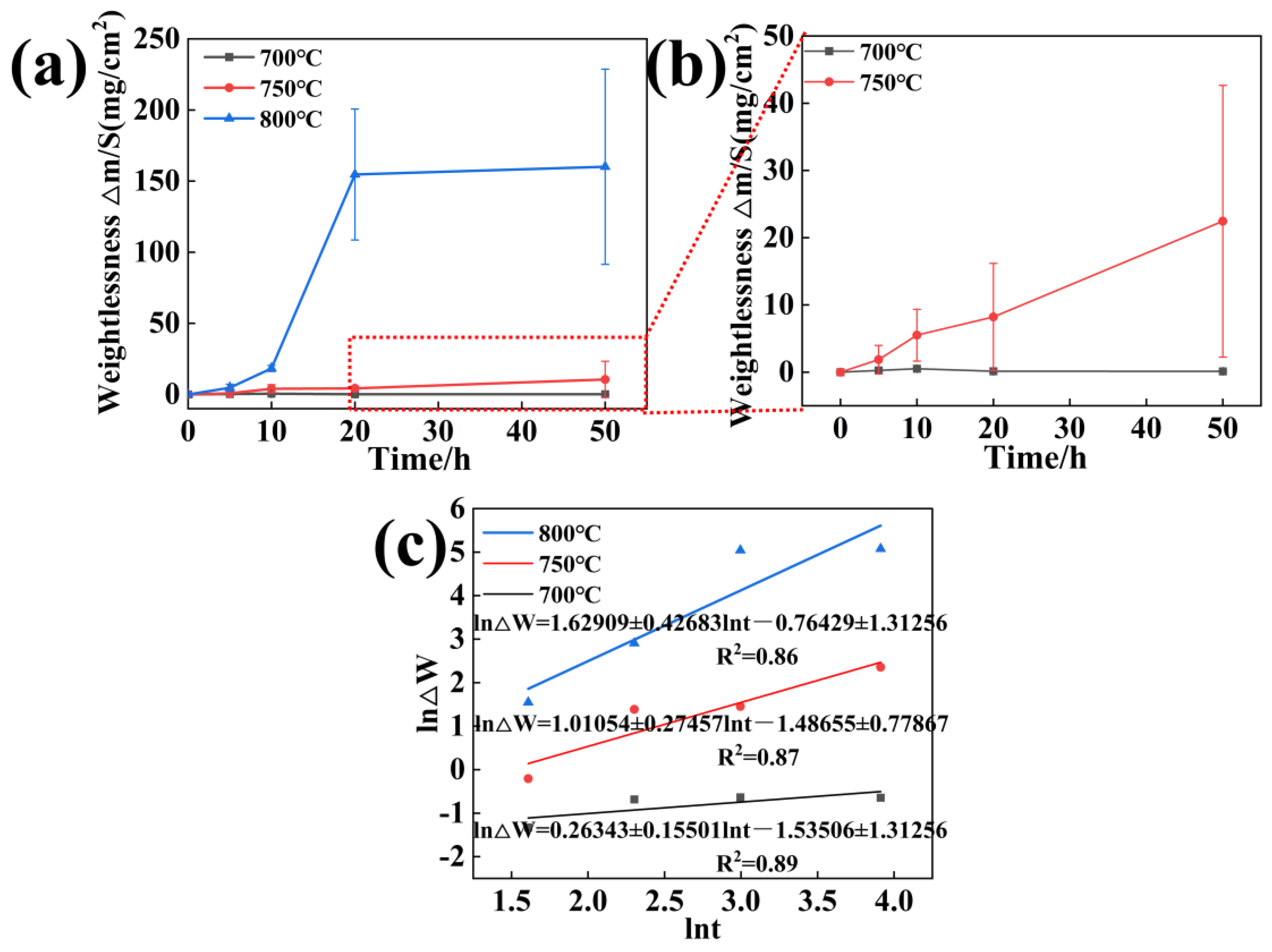
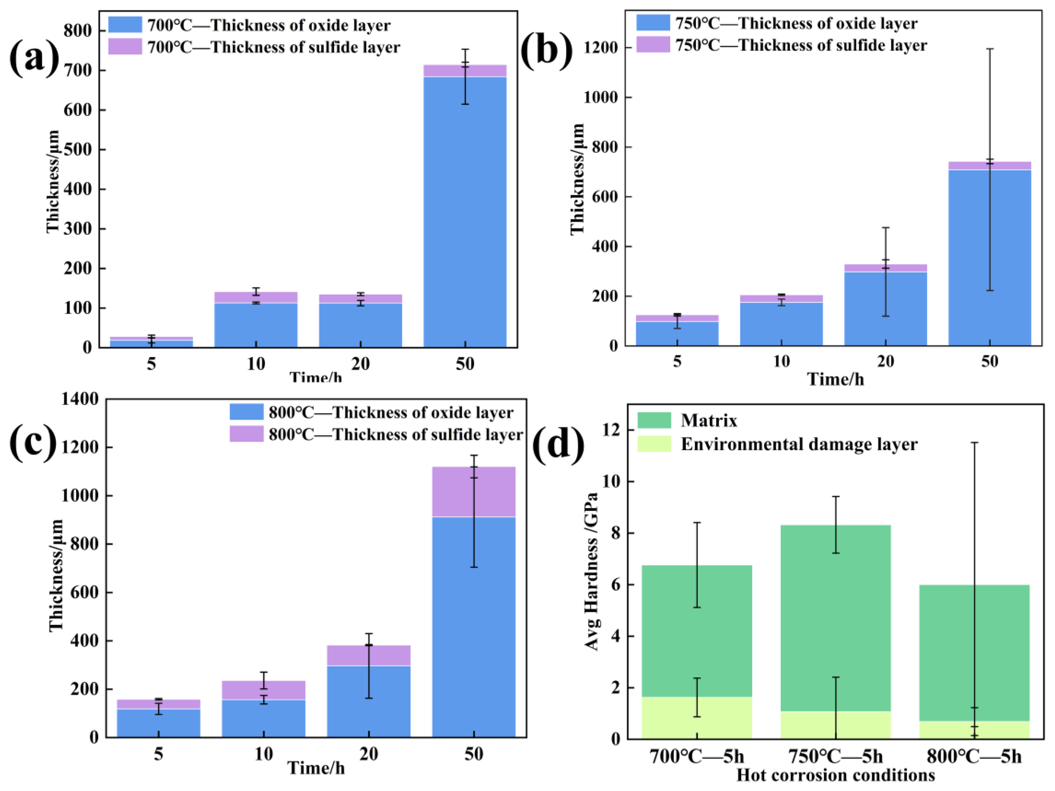
3.2. Corrosion Kinetics
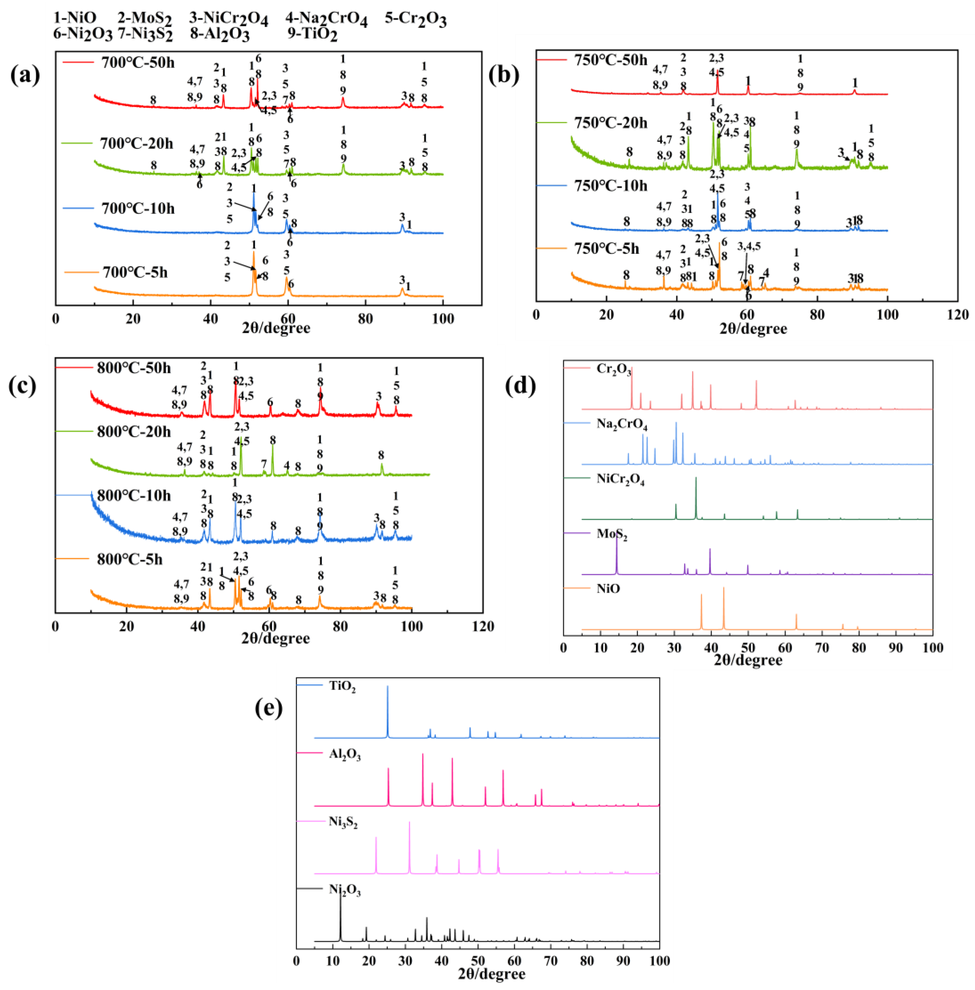
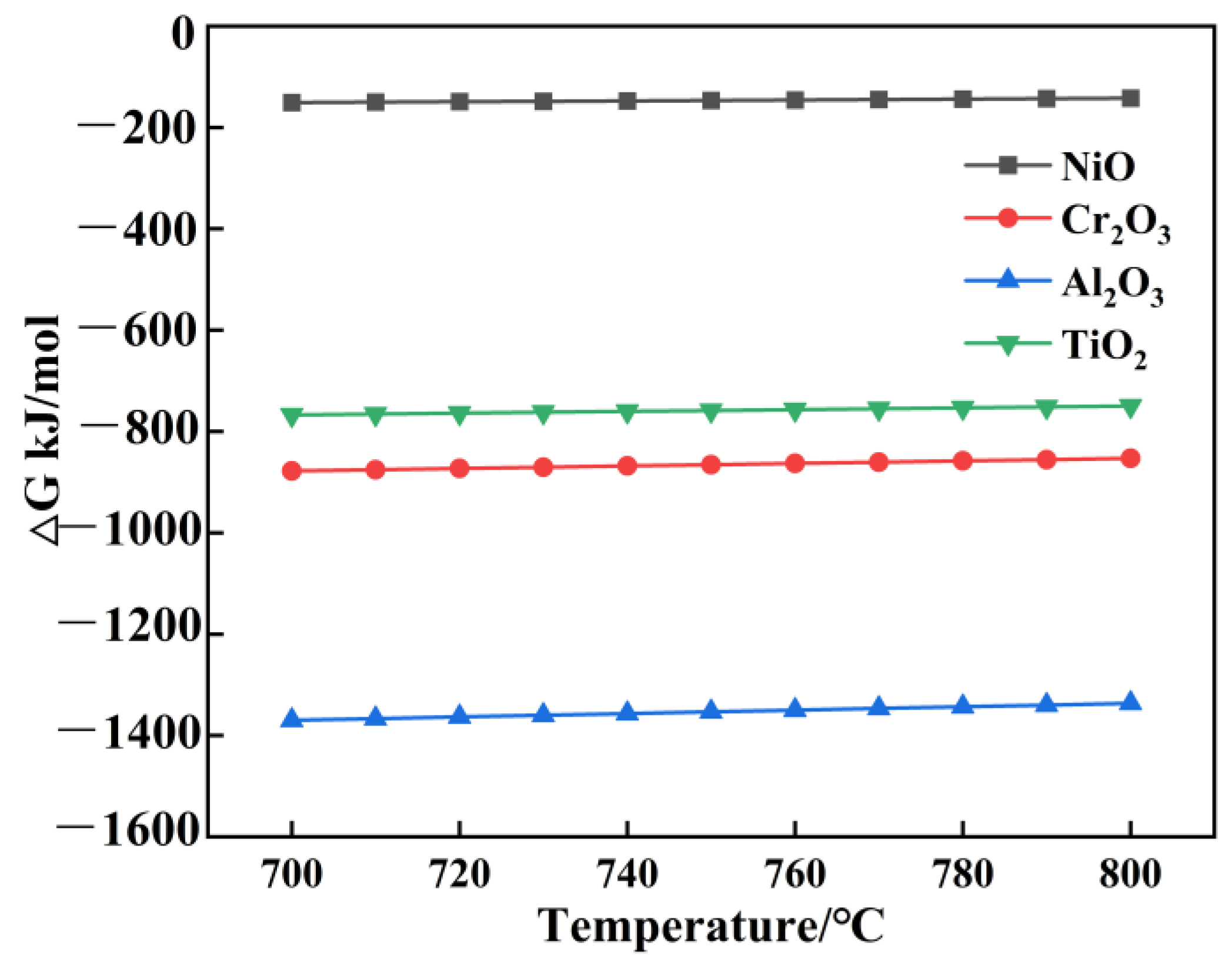
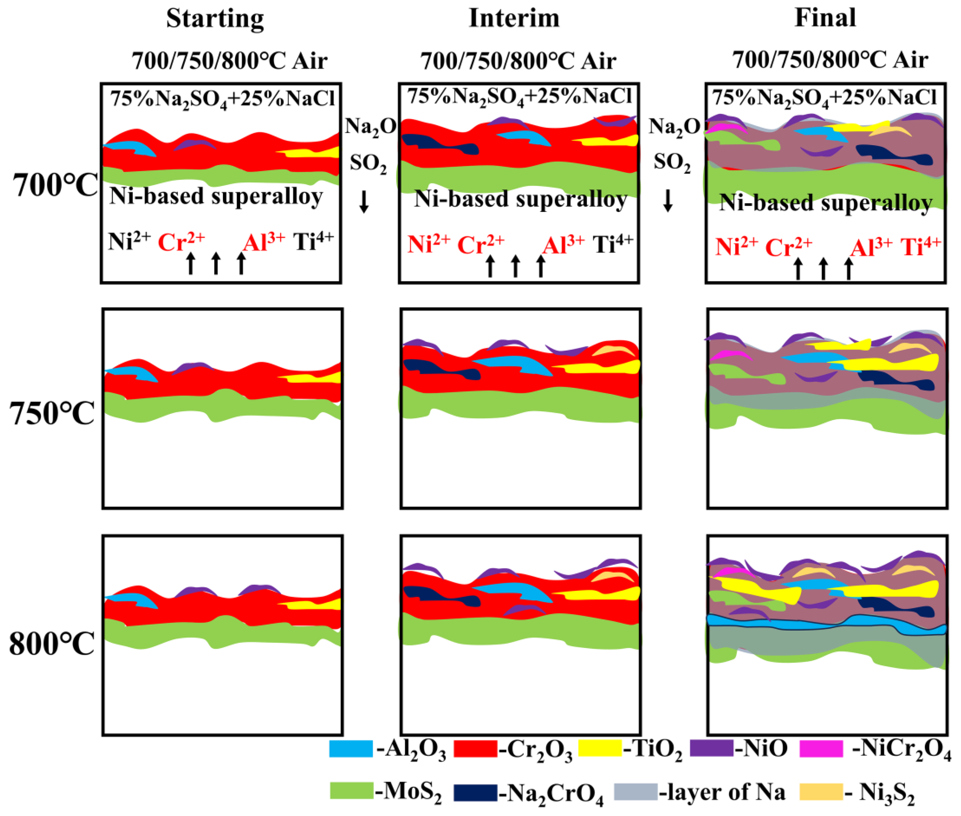
3.3. Phase Composition of Corrosion–Oxidation Products During Hot Corrosion
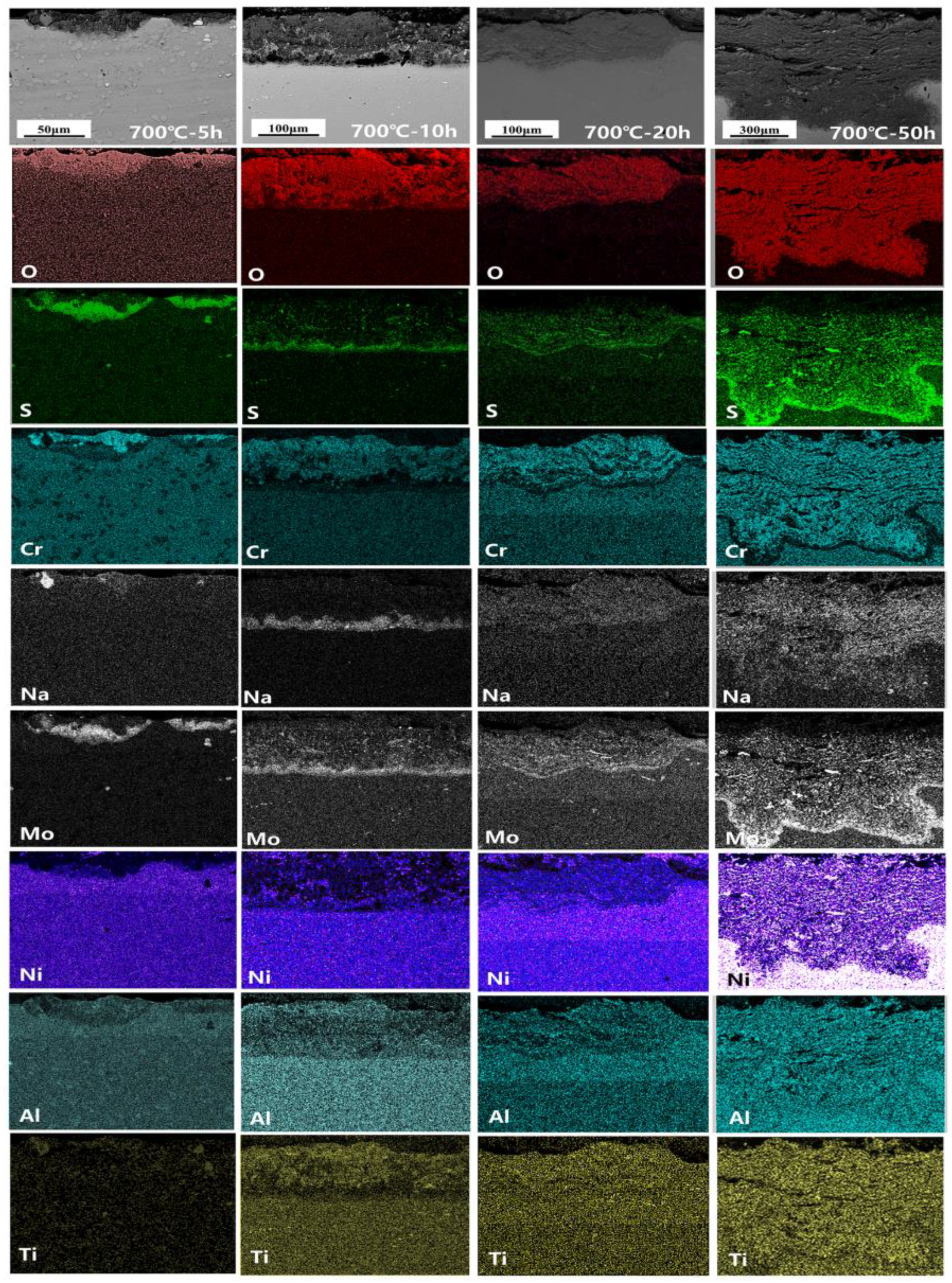
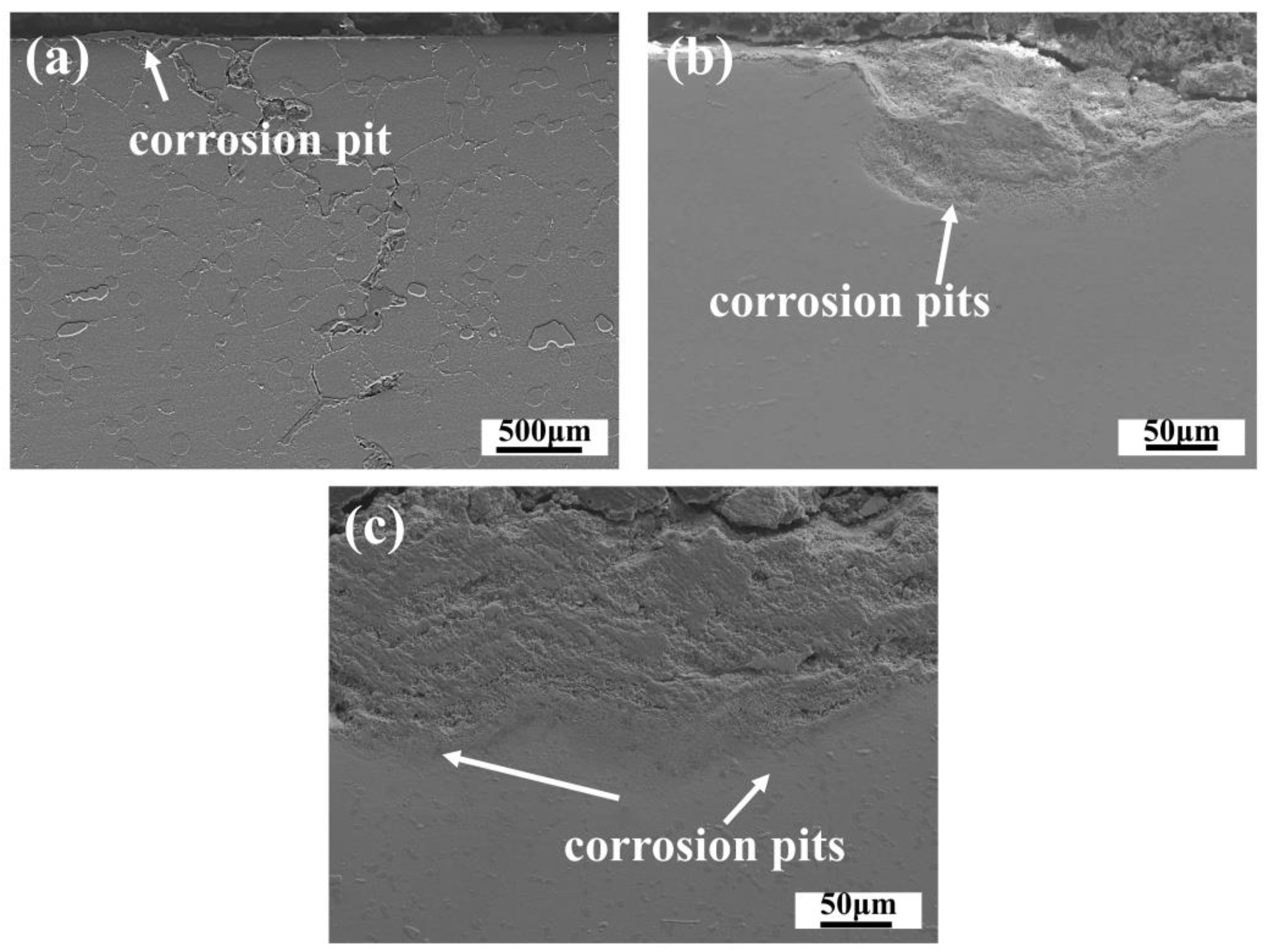
3.4. Corrosion Cross-Section Morphologies
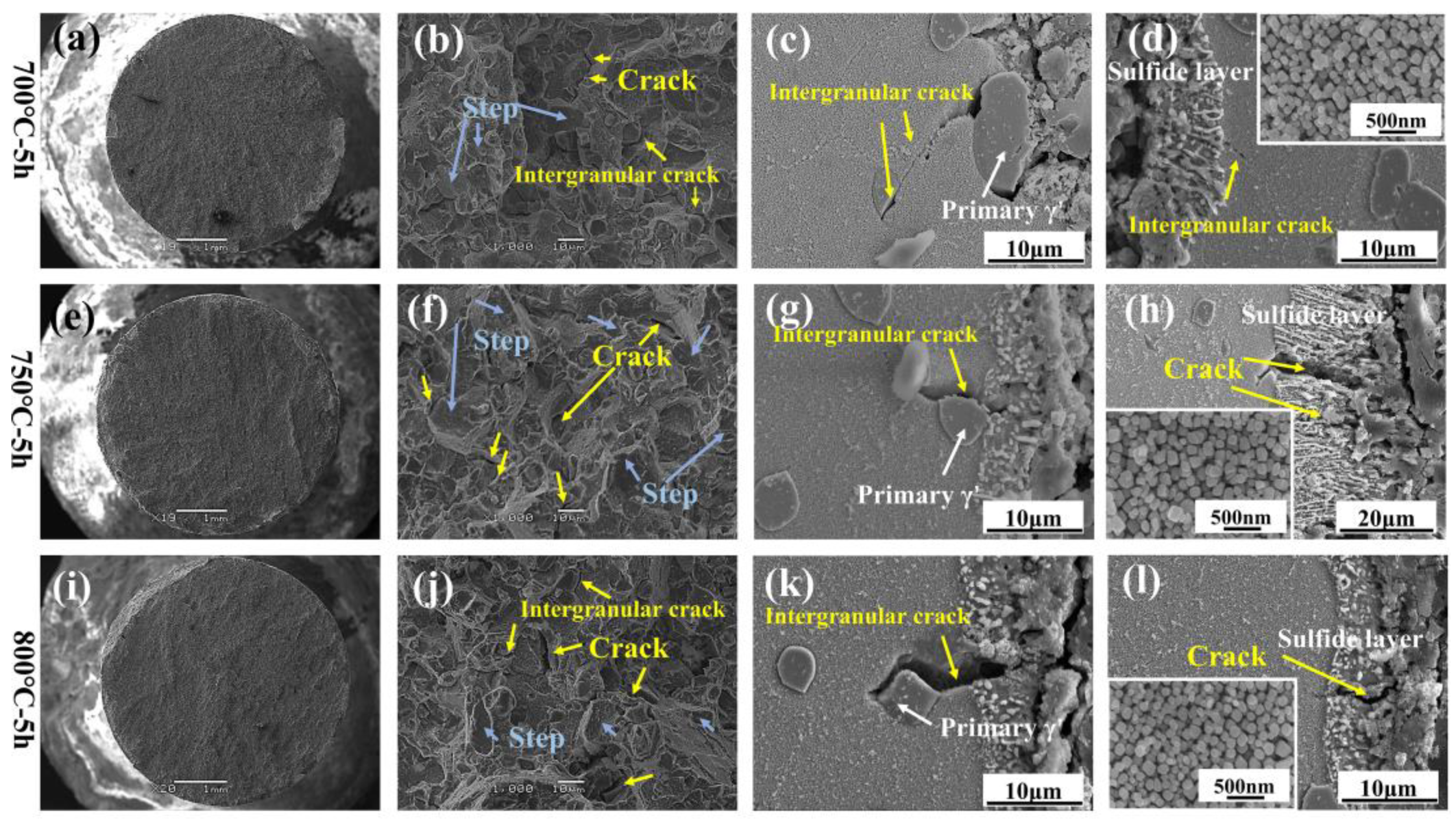
3.5. Comparison of Changes in Tensile Properties Before and After Hot Corrosion
4. Discussion
4.1. Corrosion–Oxidation Mechanism
4.2. Formation of Crack and Spalling
4.3. Mechanism of Competition for the Element Diffusion
4.4. Corrosive Properties Damage
5. Conclusions
- The damage scale is composed of inner sulfides and external oxides, and the hot corrosion element diffusion mechanism is governed by the diffusion of the Cr, Ni, Al, Ti, and Mo elements. At 700 °C and 750 °C, oxidized damage predominates, and at 800 °C, sulfurized damage takes center stage.
- Since the crucial generation conditions of external oxides are not met, the Al element content appears as a sub-surface scale at 800 °C, with Cr2O3 making up the majority of the surface scale oxides.
- During steady-state hot corrosion, the sharp increases in growth stress caused by the formation of oxides and spinels are the leading cause of the cracking and spalling of the composite oxide scale. With the increase in corrosion, there also exists a damage mechanism of dissolution–regeneration–dissolution in the surface oxide organization.
- The main effects of hot corrosion on the alloy’s tensile properties are the exfoliation cracking of the surface oxide scale, the corrosion pit on the matrix, and the sulfide scale as a source of fractures.
Author Contributions
Funding
Institutional Review Board Statement
Informed Consent Statement
Data Availability Statement
Conflicts of Interest
References
- Shi, C.X.; Zhong, Z.Y. Development and Innovation of Superalloy in China. Acta Met. Sin. 2010, 46, 1281–1288. [Google Scholar] [CrossRef]
- Jiang, H.H.; Dong, J.X.; Zhang, M.C.; Yao, Z.H. Development of Typical Hard-to-Deform Nickel-Base Superalloy for Turbine Disk Served Above 800 °C. Aeronaut. Manuf. Technol. 2021, 64, 62–73. [Google Scholar]
- Huang, S.; Sun, R.K.; Wang, L.; Dong, D.Y.; Duan, R.J.; Song, X.; Liu, Y. Microstructure evolution and fracture mechanism of a Fe–Ni–Cr superalloy during various strain rates tensile deformation at elevated temperatures. J. Mater. Sci. 2023, 58, 5901–5920. [Google Scholar] [CrossRef]
- Magazzù, A.; Marcuello, C. Investigation of Soft Matter Nanomechanics by Atomic Force Microscopy and Optical Tweezers: A Comprehensive Review. Nanomaterials 2023, 13, 963. [Google Scholar] [CrossRef]
- Liu, S.; Sun, Y.; Zhai, P.; Fan, P.; Zhang, Y.; Li, M.; Fang, J.; Wu, R.; Cai, Z. Microstructure and Properties of Nickel-Based Gradient Coatings Prepared Using Cold Spraying Combined with Laser Cladding Methods. Materials 2023, 16, 1627. [Google Scholar] [CrossRef] [PubMed]
- Schulz, U.; Menzebach, M.; Leyens, C.; Yang, Y.Q. Influence of substrate material on oxidation behavior and cyclic lifetime of EB-PVD TBC systems. Surf. Coat. Technol. 2001, 146, 117–123. [Google Scholar] [CrossRef]
- Shi, J.; Zhang, T.B.; Sun, B.; Wang, B.; Zhang, X.H.; Song, L. Isothermal oxidation and TGO growth behavior of NiCoCrAlY-YSZ thermal barrier coatings on a Ni-based superalloy. J. Alloys Compd. 2020, 844, 156093. [Google Scholar] [CrossRef]
- Li, M.; Wang, P.; Yang, Y.Q.; Yang, Y.Z.; Pei, H.P.; Wen, Z.X.; Yue, Z.F. Oxidation behavior of a nickel-based single crystal superalloy at 1100 °C under different oxygen concentration. J. Mater. Sci. 2022, 57, 3822–3841. [Google Scholar] [CrossRef]
- Long, H.B.; Mao, S.C.; Liu, Y.N.; Zhang, Z.; Han, X.D. Microstructural and compositional design of Ni-based single crystalline superalloys—A review. J. Alloys Compd. 2018, 743, 203–220. [Google Scholar] [CrossRef]
- Park, S.J.; Seo, S.M.; Yoo, Y.S.; Jeong, H.W. Effects of Al and Ta on the high temperature oxidation of Ni-based superalloys. Corros. Sci. 2014, 90, 305–312. [Google Scholar] [CrossRef]
- Ismail, F.B.; Vorontsov, V.A.; Lindley, T.C.; Hardy, M.; Dye, D. Shollock, Alloying effects on oxidation mechanisms in polycrystalline Co–Ni base superalloys. Corros. Sci. 2016, 116, 44–52. [Google Scholar] [CrossRef]
- Liu, Z.S.; Ding, Q.Q.; Zhou, Q.; Yao, X.; Wei, X.; Zhao, X.B.; Wang, Y.; Zhang, Z.; Bei, H. The effect of oxidation on microstructures of a Ni-based single crystal superalloy during heat-treatment and simulated service conditions. J. Mater. Sci. 2023, 58, 6343–6360. [Google Scholar] [CrossRef]
- Li, S.L.; Qi, H.Y.; Yang, X.G. Oxidation-induced damage of an uncoated and coated nickel-based superalloy under simulated gas environment. Rare Met. 2018, 37, 204–209. [Google Scholar] [CrossRef]
- Iyer, A.H.S. Oxidation Induced Failure of Superalloys: High Temperature Crack Growth and Oxide Scale Properties. Ph.D. Dissertation, Chalmers University of Technology, Gothenburg, Sweden, 2017. [Google Scholar]
- Sun, B.; Zhang, T.B.; Song, L.; Zhang, L. Oxidation behavior in static air and its effect on tensile properties of a powder metallurgy EP962NP nickel-based superalloy. J. Alloys Compd. 2023, 934, 167795. [Google Scholar] [CrossRef]
- Li, D.H.; Chen, J.X.; Etim, I.; Liu, Y.; Wu, C.J.; Wang, J.H.; Su, X.P. High temperature oxidation behavior of Ni-based superalloy Nimonic95 and the effect of pre-oxidation treatment. Vacuum 2021, 194, 110582. [Google Scholar] [CrossRef]
- Mahobia, G.S.; Paulose, N.; Singh, V. Hot corrosion behavior of superalloy IN718 at 550 and 650 °C. J. Mater. Eng. Perform. 2013, 22, 2418–2435. [Google Scholar] [CrossRef]
- Wei, C.; Wang, Z.J.; Chen, J.G. Sulfuration corrosion failure analysis of Inconel 600 alloy heater sleeve in high-temperature flue gas. Eng. Fail. Anal. 2022, 135, 106111. [Google Scholar] [CrossRef]
- Birbilis, N.; Buchheit, R.G. Measurement and discussion of low-temperature hot corrosion damage accumulation upon nickel-based superalloy Rene 104. Metall. Mater. Trans. A 2008, 39, 3224–3232. [Google Scholar] [CrossRef]
- Nazmy, M.Y. The effect of environment on the high temperature low cycle fatigue behaviour of cast nickel-base IN-738 alloy. Mater. Sci. Eng. 1982, 55, 231–237. [Google Scholar] [CrossRef]
- Wang, H.; Dong, H.; Cai, Z.W.; Liu, Y.Z.; Wang, W.Z. Fatigue behaviors of a nickel-based superalloy after hot-corrosion: Experiments and peridynamic simulations. Int. J. Fatigue 2023, 180, 108070. [Google Scholar] [CrossRef]
- Chang, W.; Ji, Y.L.; Li, J.P. Application analysis in the development and production of aero-engine materials. Aviat. Stand-Ardisation Qual. 2014, 3, 3. [Google Scholar]
- Xu, W.X.; Xu, W.C. Comparison and understanding of the main changes of GB/T228.1-2021. Phys. Chem. Test. Phys. Div. 2022, 58, 4. [Google Scholar]
- Shi, W.; Zhang, L.; Li, X. Application of GB/T6394-2017 in titanium alloy grain size assessment. Phys. Chem. Test. Phys. Div. 2019, 55, 5. [Google Scholar]
- Gui, Y.T.; Zhao, M.; Jiang, P.R.; Ye, W.; Zhao, J.Q.; Zhao, Y.S.; Qiao, Y.Q.; Wu, S.S.; Yan, Y.W. New insights into effects of Ru on the oxidation behaviour of Ni-based single-crystal superalloys at 1150 °C. Corros. Sci. 2023, 223, 111464. [Google Scholar] [CrossRef]
- Yang, B.S.; Li, B.; Chen, X.X.; Zhang, Y.N.; Li, Y.Z. Influence of temperature on hot corrosion behavior of GH4169 superalloy subjected to Na2SO4-NaCl salts attack. Mater. Chem. Phys. 2024, 325, 129731. [Google Scholar] [CrossRef]
- Zheng, L.; Maicang, Z.; Jianxin, D. Hot corrosion behavior of powder metallurgy Rene95 nickel-based superalloy in molten NaCl–Na2SO4 salts. Mater. Des. 2011, 32, 1981–1989. [Google Scholar] [CrossRef]
- Jiang, J.F.; Xiao, G.F.; Wang, Y.; Liu, Y.Z. High temperature oxidation behavior of the wrought Ni-based superalloy GH4037 in the solid and semi-solid state. J. Alloys Compd. 2019, 784, 394–404. [Google Scholar] [CrossRef]
- Wo, J.; Pang, H.T.; Wilson, A.S.; Hardy, M. The Isothermal Oxidation of a New Polycrystalline Turbine Disk Ni-Based Superalloy at 800 °C and Its Modification with Pre-oxidation. Metall. Mater. Trans. A 2023, 54, 1946–1960. [Google Scholar] [CrossRef]
- Jiang, R.; Zhang, L.C.; Zhao, Y.; Chen, X.H. Effects of hot corrosion on fatigue performance of GH4169 alloy. J. Mater. Eng. Perform. 2021, 30, 2300–2308. [Google Scholar] [CrossRef]
- Song, Y.D.; Ling, C.; Zhang, L.C.; Li, M.L.; Guo, J.W.; Jiang, R. Research Progress on Hot Corrosion-Fatigue of Aero-engine and Gas Turbine Hot-Section Components. J. Nanjing Univ. Aeonautics Astronaut. 2022, 54, 771–788. [Google Scholar]
- Abbasi, M.; Kim, D.; Shim, J.H.; Jung, W.S. Effects of alloyed aluminum and titanium on the oxidation behavior of INCONEL 740 superalloy. J. Alloys Compd. 2016, 658, 210–221. [Google Scholar] [CrossRef]
- Yu, K.P.; Jiang, H.; Xu, X.Y.; Huang, M.X. Design of corrosion-resistant alloys for preventing oxidation-induced nanoscale Cr-depletion by inclusion engineering. Mater. Des. 2024, 244, 113146. [Google Scholar] [CrossRef]
- Han, S.H.; Choe, B.; Kim, D.; Kim, J.H. The effect of TCP-σ precipitates on surface pitting and cracking in a Ni-based superalloy turbine blade. Eng. Fail. Anal. 2024, 158, 107989. [Google Scholar] [CrossRef]
- Yang, S.Y. Thermodynamic Analysis and Alloy Design of Co-AL-W Based Superalloy. Ph.D. Dissertation, Northeastern University, Shenyang, China, 2012. [Google Scholar]
- Douglass, D.L. A critique of internal oxidation in alloys during the post-wagner era. Oxid. Met. 1995, 44, 81–111. [Google Scholar] [CrossRef]
- Andreev, Y.Y. Adsorption equilibrium at the metal-oxide film interface in the oxidation reactions of Ni, Cr, and their alloys. Russ. J. Phys. Chem. 2007, 81, 967–973. [Google Scholar] [CrossRef]
- Tsaur, C.C.; Rock, J.C.; Wang, C.J.; Su, Y.J. The hot corrosion of 310 stainless steel with pre-coated NaCl/Na2SO4 mixtures at 750 °C. Mater. Chem. Phys. 2005, 89, 445–453. [Google Scholar] [CrossRef]
- Liu, S.; Feng, J.; Luo, X.; Chen, X. Effect of special grain boundary on hot corrosion path in Incoloy825 alloy. J. Mater. Sci. 2022, 57, 15560–15580. [Google Scholar] [CrossRef]
- Li, P.; Li, T.; Zhao, J.; Pang, S.J. Hot corrosion behaviors of super 304H austenitic stainless steel pre-coated in Na2SO4–25%NaCl mixture salt film. J. Iron Steel Res. Int. 2018, 25, 1149–1155. [Google Scholar] [CrossRef]
- Smialek, J.L. A deterministic interfacial cyclic oxidation spalling model. Acta Mater. 2003, 51, 469–483. [Google Scholar] [CrossRef]
- Qu, W.; Li, J.; Hill, J.M.; Ivey, D.G. Electrical and microstructural characterization of spinel phases as potential coatings for SOFC metallic interconnects. J. Power Sources 2006, 153, 114–124. [Google Scholar] [CrossRef]
- Birks, N.; Meier, G.; Pettit, F. Introduction to the High Temperature, Oxidation of Metals, 2nd ed.; Cambridge University Press: New York, NY, USA, 2006. [Google Scholar]
- Xu, C.; Gao, W. Pilling-Bedworth ratio for oxidation of alloys. Mater. Res. Innov. 2000, 3, 231–235. [Google Scholar] [CrossRef]
- He, X.; Li, W.; Kong, D.C.; Zhang, W. The kinetics of pitting corrosion in a defect-contained Hastelloy X alloy fabricated by laser powder bed fusion. Corros. Sci. 2024, 237, 112321. [Google Scholar] [CrossRef]
- Gabb, T.P.; Telesman, J.; Hazel, B.; Mourer, D. The effects of hot corrosion pits on the fatigue resistance of a disk superalloy. J. Mater. Eng. Perform. 2010, 19, 77–89. [Google Scholar] [CrossRef]
- Jack, T.; Gabb, T.P.; Yamada, Y. Fatigue resistance of a hot corrosion exposed disk superalloy at varied test temperatures. Mater. High Temp. 2016, 33, 517–527. [Google Scholar]
- Dong, N. Effects of Alloying Elements on the Formation and Bonding Strength of New Alumina-Forming Austenitic Heat-Resistant Steel/Oxide Scale Interface. Ph.D. Dissertation, Taiyuan University of Technology, Taiyuan, China, 2017. [Google Scholar]
- Giggins, C.S.; Pettit, F.S. Oxidation of Ni-Cr-Al alloys between 1000 and 1200 °C. J. Electrochem. Soc. 1971, 118, 1782. [Google Scholar] [CrossRef]
- Perez, T.; Monceau, D.; Desgranges, C. Kinetic oxidation model including the transient regime for a single crystal nickel-based superalloy over the temperature range 750–1300 °C. Corros. Sci. 2022, 206, 110485. [Google Scholar] [CrossRef]
- Young, D. Predicting Internal Oxidation: Building on the Wagner Model. Mater. Sci. Forum 2011, 696, 1–11. [Google Scholar] [CrossRef]
- Park, J.W.; Altstetter, C.J. The diffusion and solubility of oxygen in solid nickel. Metall. Trans. A 1987, 18, 43–50. [Google Scholar] [CrossRef]
- Allison, H.W.; Samelson, H. Diffusion of aluminum, magnesium, silicon, and zirconium in nickel. J. Appl. Phys. 1959, 30, 1419–1424. [Google Scholar] [CrossRef]
- Pettit, F.S. Oxidation mechanisms for nickel-aluminum alloys at temperatures between 900 °C and 1300 °C. Trans. Metall. Soc. AIME 1967, 239, 1296–1305. [Google Scholar]
- Nesbitt, J.A. Predicting Minimum Aluminum Concentrations for Protective Scale Formation on Ni-Base Alloys: II. Cyclic Oxidation. J. Electrochem. Soc. 1989, 13, 1518. [Google Scholar] [CrossRef]
- Zhao, W.; Kang, Y.H.; Orozco, J.M.A.; Gleeson, B.M. Quantitative approach for determining the critical volume fraction for the transition from internal to external oxidation. Oxid. Met. 2015, 83, 187–201. [Google Scholar] [CrossRef]
- Jiang, H.; Dong, J.X.; Zhang, M.C.; Guo, W.M. Microstructural Evolution and Oxidation Behavior of Alloy Ni-13Mo-13Cr-9W-3Fe-3Ti-2Al during Isothermal Exposure at 900 °C. Metall. Mater. Trans. A 2019, 50, 4331–4343. [Google Scholar] [CrossRef]
- Waeytens, M.; Syed, A.U.; Roberts, T.; Martinez, F.D. A microscopy study of nickel-based superalloys performance in type I hot corrosion conditions. Mater. High Temp. 2023, 40, 272–282. [Google Scholar] [CrossRef]


| C | Cr | W | Mo | Ti | Nb | Al | Co | V | Ni |
|---|---|---|---|---|---|---|---|---|---|
| 0.05 | 11.3 | 3.0 | 4.5 | 2.6 | 3.1 | 3.8 | 14.7 | 0.6 | Balanced |
| O | Al | S | Ti | Cr | Ni | |
|---|---|---|---|---|---|---|
| Point 1 | 37.69 | 1.81 | 0.49 | 2.55 | 15.22 | 42.24 |
| Point 2 | 48.98 | 1.93 | 2.91 | 7.64 | 32.37 | 6.76 |
| Oxides | Cr2O3 | NiCr2O4 |
|---|---|---|
| PBR | 2.07 | 2.05 |
| Eoxides | 260 | 233 |
| σG | 71.35 GPa | 62.99/GPa |
| Oxides | Cr2O3 | NiCr2O4 |
|---|---|---|
| 9.6 × 10⁻⁶ K−1 | 7.6 × 10⁻⁶ K−1 | |
| 15.2 × 10⁻⁶ K−1 | 15.2 × 10⁻⁶ K−1 | |
| (700 °C) | 0.99 GPa | 1.20 GPa |
| (750 °C) | 1.06 GPa | 1.29 GPa |
| (800 °C) | 1.13 GPa | 1.38 GPa |
| Vm | DO | DB | ||
|---|---|---|---|---|
| 7.20 | 1.75 × 10⁻⁴ | 7.07 × 10⁻¹⁰ | 8.34 × 10⁻¹⁰ | 9.78% |
Disclaimer/Publisher’s Note: The statements, opinions and data contained in all publications are solely those of the individual author(s) and contributor(s) and not of MDPI and/or the editor(s). MDPI and/or the editor(s) disclaim responsibility for any injury to people or property resulting from any ideas, methods, instructions or products referred to in the content. |
© 2025 by the authors. Licensee MDPI, Basel, Switzerland. This article is an open access article distributed under the terms and conditions of the Creative Commons Attribution (CC BY) license (https://creativecommons.org/licenses/by/4.0/).
Share and Cite
Meng, X.; Lyu, S.; Xie, X.; Tang, C.; Yu, W.; Hou, W.; Wang, C.; Qu, J.; Du, J. Hot Corrosion Behavior and Damage Mechanism on Yield Property of Nickel-Based Superalloy. Materials 2025, 18, 1749. https://doi.org/10.3390/ma18081749
Meng X, Lyu S, Xie X, Tang C, Yu W, Hou W, Wang C, Qu J, Du J. Hot Corrosion Behavior and Damage Mechanism on Yield Property of Nickel-Based Superalloy. Materials. 2025; 18(8):1749. https://doi.org/10.3390/ma18081749
Chicago/Turabian StyleMeng, Xinyu, Shaomin Lyu, Xingfei Xie, Chao Tang, Wugang Yu, Weixue Hou, Chengyu Wang, Jinglong Qu, and Jinhui Du. 2025. "Hot Corrosion Behavior and Damage Mechanism on Yield Property of Nickel-Based Superalloy" Materials 18, no. 8: 1749. https://doi.org/10.3390/ma18081749
APA StyleMeng, X., Lyu, S., Xie, X., Tang, C., Yu, W., Hou, W., Wang, C., Qu, J., & Du, J. (2025). Hot Corrosion Behavior and Damage Mechanism on Yield Property of Nickel-Based Superalloy. Materials, 18(8), 1749. https://doi.org/10.3390/ma18081749