2.1. Test Matrix
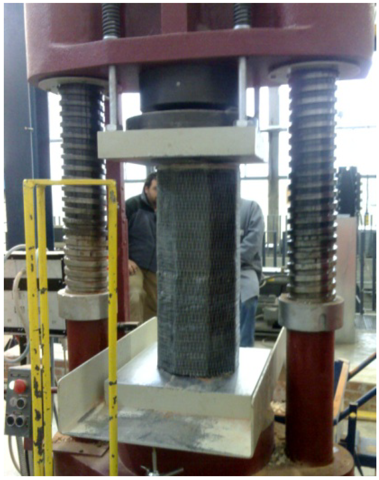
Twenty-three solid brick masonry columns were subjected to uni-axial compression in order to test the column strength confined by steel composites.
Table 1 shows the experimental program and type of reinforcement. The purpose was to evaluate the increase in compressive strength of masonry columns produced by the reinforcement wrapping and to record the axial stress-strain curve. Another important objective was to find the failure mode of the masonry columns.
Table 1.
Experimental program.
Table 1.
Experimental program.
| Specimen | Shape of Cross-section | Matrix Type | Reinforcement Type | Reinforcing Scheme |
|---|
| 1 | octagonal | - | - | - |
| 2 | square | - | - | - |
| 3 | square | epoxy | Type 1 | Continuous wrap |
| 4 | square | epoxy | Type 1 | Continuous wrap |
| 5 | octagonal | epoxy | Type 2 | Continuous wrap |
| 6 | octagonal | epoxy | Type 2 | Discontinuous wrap |
| 7 | octagonal | epoxy | Type 2 | Continuous wrap |
| 8 | octagonal | epoxy | Type 2 | Discontinuous wrap |
| 9 | octagonal | epoxy | Type 1 | Continuous wrap |
| 10 | octagonal | epoxy | Type 1 | Discontinuous wrap |
| 11 | octagonal | epoxy | Type 1 | Continuous wrap |
| 12 | octagonal | epoxy | Type 2 | Discontinuous wrap |
| 13 | octagonal | epoxy | Type 1 | Discontinuous wrap |
| 14 | octagonal | epoxy | Type 1 | Continuous wrap |
| 15 | octagonal | epoxy | Type 2 | Discontinuous wrap |
| 16 | octagonal | epoxy | Type 2 | Continuous wrap |
| 17 | square | epoxy | Type 1 | Continuous wrap |
| 18 | square | epoxy | Type 1 | Continuous wrap |
| 19 | square | epoxy | Type 1 | Discontinuous wrap |
| 20 | square | epoxy | Type 1 | Discontinuous wrap |
| 21 | square | epoxy | Type 1 | Discontinuous wrap |
| 22 | square | epoxy | Type 1 | Discontinuous wrap |
| 23 | square | epoxy | Type 1 | Discontinuous wrap |
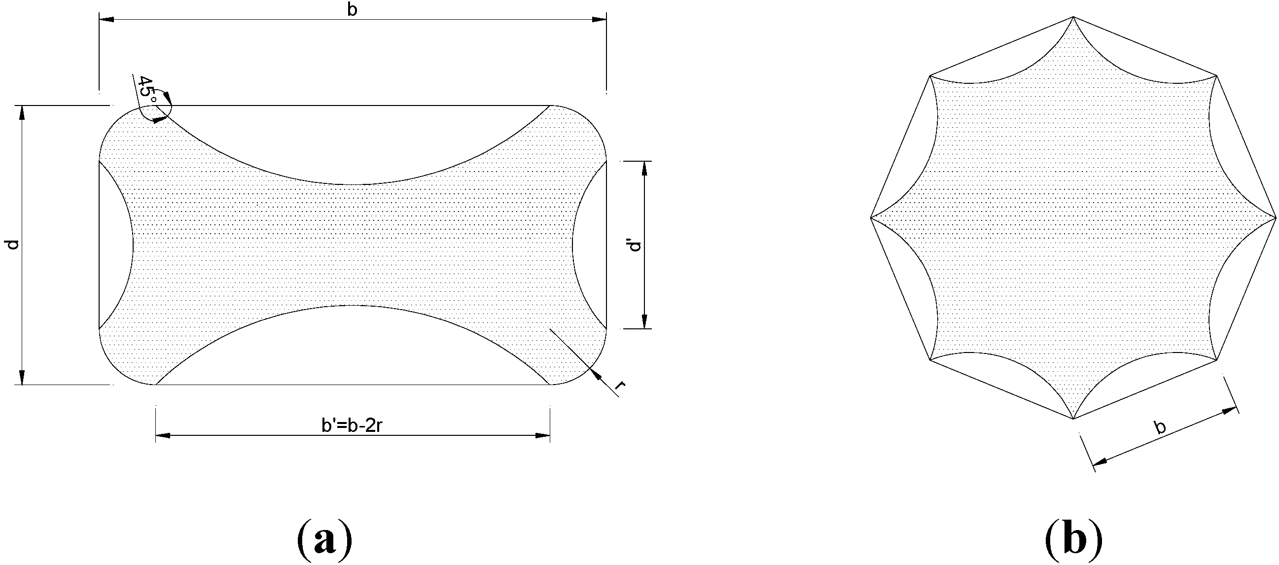
Using 245 × 120 × 55 mm solid clay bricks, two types of columns of differing cross-sections (squares with sides of 245 mm and octagonals with sides of 100 mm) were constructed. Octagonal cross-section masonry columns are in fact quite common in Italy and the rest Europe in many historical constructions such as churches, monasteries and porticoes. Of the 23 samples in the series 10 had square cross-sections while the remaining 13 had octagonal sections. The geometry of the specimens with the two cross-sections is shown in
Figure 1. All masonry columns were 500 mm tall, while the thickness of mortar bed joints was equal to 8 ÷ 10 mm.
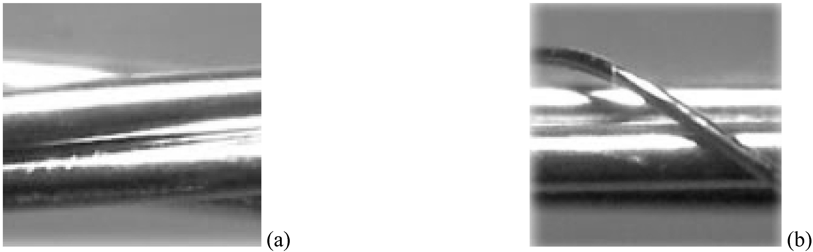
Another test variable was the type of steel cords (Type 1 or 2). One distinctive feature of these materials is their macroscopic structure. All the fibers are made up of high-strength steel filaments covered with a layer of brass to prevent oxidation of the metallic cords. These cords are placed side by side and glued to a thin polyester mesh to allow them to be packaged in the form of a strip. Placing these metallic cords side-by-side and gluing them onto thin polyester meshes results in a product in the form of sheets with a density of 12 cords/inch (4.72 cords/cm), which are then wound on bobbins.
The Type 2 cord is made by twisting five individual filaments together (three straight filaments wrapped by two filaments at a high twist angle) (
Figure 2a). The Type 1 cord results from winding four single high strength metallic filaments together: three filaments are wound together by a single external filament of a smaller diameter (
Figure 2b). Type 1 was used only for reinforcement of square cross-section columns, and Type 2 for both square and octagonal cross-sections columns.
Figure 1.
Geometry of cross-sections of masonry columns (dimensions in mm) (a) square cross-section; (b) octagonal cross-section.
Figure 1.
Geometry of cross-sections of masonry columns (dimensions in mm) (a) square cross-section; (b) octagonal cross-section.
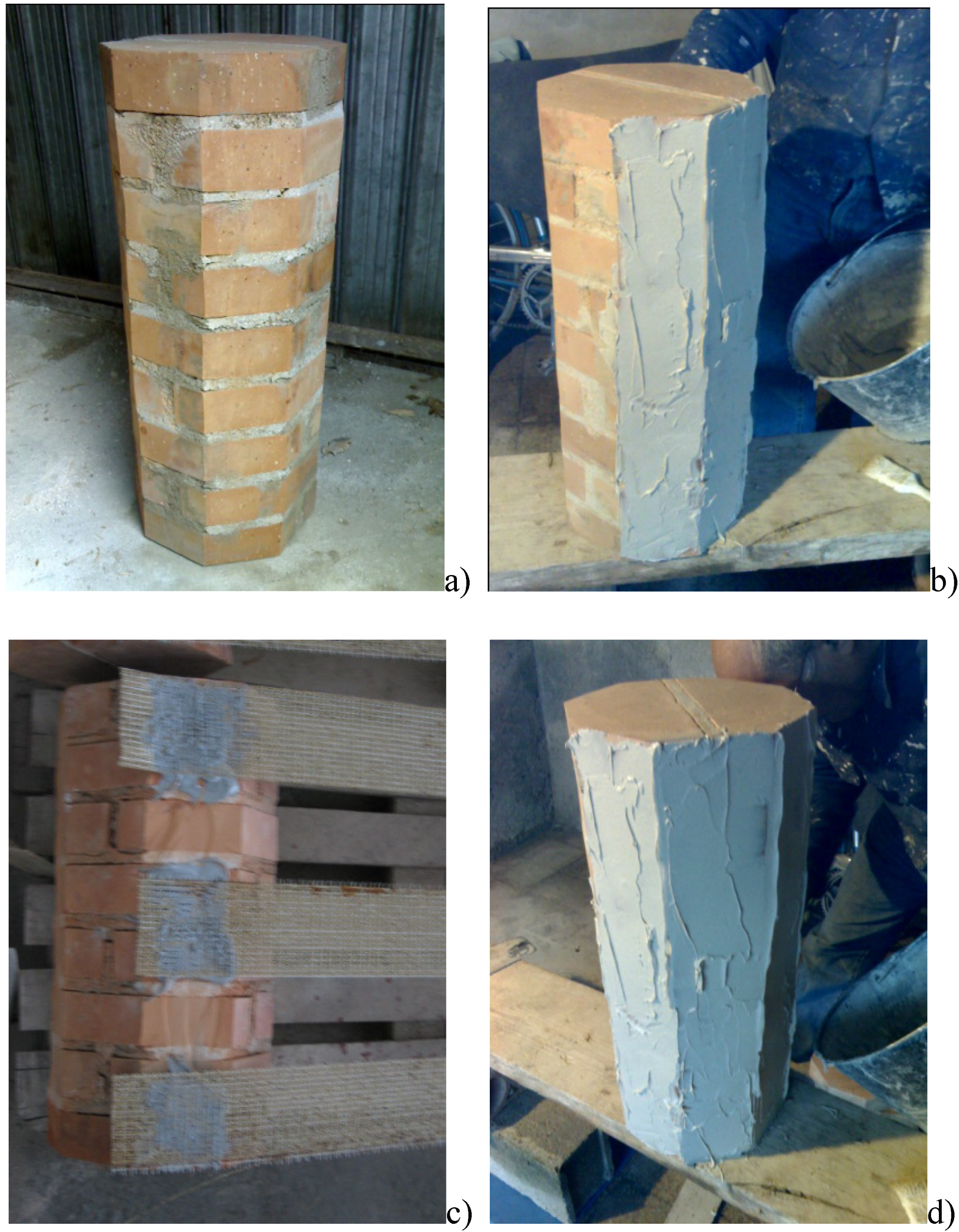
The steel cords were glued by using a two-component epoxy resin. Reinforcement was executed in the following steps (
Figure 3): (a) cleaning of the column surfaces of all extraneous material to improve the adhesion between resin and masonry; (b) application of a first layer of matrix; (c) application of a unidirectional SRP sheet; (d) application of a second layer of epoxy resin or cementitious mortar. All specimens were wrapped with orientation perpendicular to their axis.
Figure 2.
(a) 3X2 cord (Type 2); (b) 3SX cord (Type 1).
Figure 2.
(a) 3X2 cord (Type 2); (b) 3SX cord (Type 1).
Figure 3.
(a) Cleaning of the column surfaces; (b) Application of a first layer of matrix; (c) Application of a unidirectional SRP sheet; (d) Application of a second layer of epoxy resin or cementitious mortar.
Figure 3.
(a) Cleaning of the column surfaces; (b) Application of a first layer of matrix; (c) Application of a unidirectional SRP sheet; (d) Application of a second layer of epoxy resin or cementitious mortar.
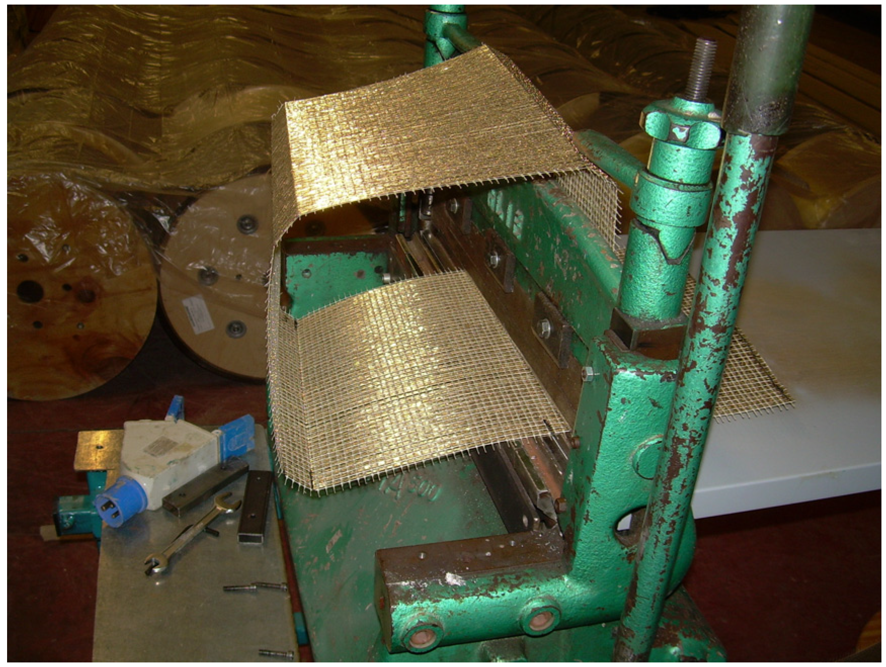
The steel fibers were cold-bended with an appropriate apparatus (
Figure 4) to form a square section identical to the cross-sections of the masonry columns. This was necessary due to the bending stiffness of the steel filers which cause debonding of the fibers on the corners of the masonry columns.
Figure 4.
Cord cold bending (used only for square cross-section columns).
Figure 4.
Cord cold bending (used only for square cross-section columns).
Particular attention was given to surface preparation and corner reinforcement: Before wrapping the SRP sheets, masonry surface defects were filled with cementitious mortar. The edges of the columns were rounded with a radius of 30 mm to prevent any stress concentrations within the reinforcing layers. Wrapping of the SRP sheets took place after curing for at least 28 days in laboratory conditions.
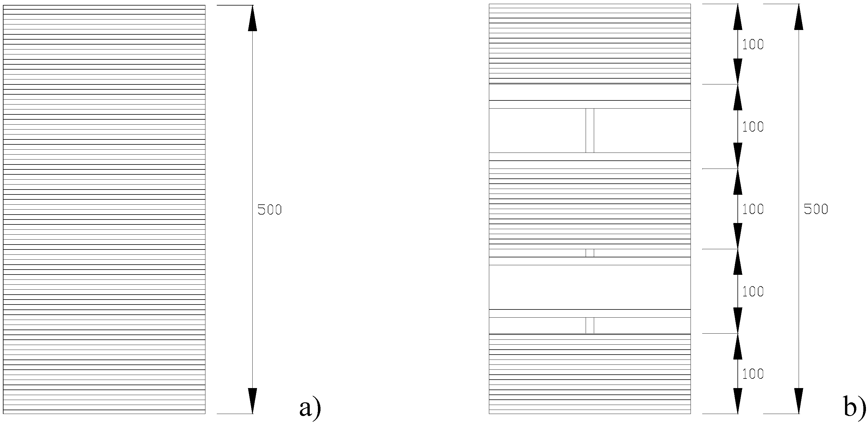
Figure 5.
Reinforcement layout: (a) continuous wrap; (b) discontinuous wrap.
Figure 5.
Reinforcement layout: (a) continuous wrap; (b) discontinuous wrap.
Two different configurations of the reinforcing system were investigated: SRP sheets are applied as external reinforcement along the perimeter of the masonry columns in the form of continuous and discontinuous wrap, respectively. To elaborate, in the first case the confinement was provided by a continuous laminate composed of two SRP strips of 300 mm width each (
Figure 5a); whereas in the second case the confinement was provided by three SRP strips, 100 mm wide and 200 mm spaced (
Figure 5b). In both cases, the overlap of the sheet in circumferential direction is 100 mm, and there is no lengthwise overlap.
The series of masonry columns are identified by a three index code, in which the first indicates the cross-section shape (S = square cross-section; O = Octagonal cross-section); the second indicates the type of steel cords (3SX = Type 1 cords; 3X2 = Type 2 cords); the third the reinforcing system (C = Continuous wrap; D = Discontinuous wrap).

