1. Introduction
Increasing world population and limited natural resources require us to rethink how we utilize our forests more productively to construct effective building products for houses. Forests play a critical role in sequestering carbon and building products and can further this cause by continuing to store the carbon for a prolonged period. As an order of magnitude, a tree on an average absorbs one ton of CO
2 and produces 0.7 tons of O
2 for every cubic meter of growth [
1], and every cubic meter of wood as a building material can reduce CO
2 emissions by an average of 2 tons compared to other building materials such steel and concrete [
2]. A sustainable forest management plan to protect forests against fire, insects, and disease should consider thinning operations that result in improving forest health. Often, this requires the removal of small-diameter timber (SDT) at a cost and requires high-value markets or high-volume usage of these low-quality logs to recover the forest treatment costs. For example, the average cost for a forest service thinning (approximately
$70/dry ton) is usually more than the market value of the SDT removed (energy and chip markets pay approximately
$25 to
$35/dry ton) [
3]. Besides existing products such as medium-density fiberboard (MDF) and oriented strand board (OSB) produced from SDT, it is worth developing new products by converting these low-quality SDTs into more robust and versatile building products that would meet the structural performance as well as energy requirements.
Sandwich structures are widely used in many areas like aerospace, automotive, civil, building construction, and marine industries because their clever construction reduces their weight while increasing their mechanical performance [
4]. However, those with hollow cores have attracted interest from researchers because the hollow geometry of the core can be used to improve the thermal performance when they are filled with appropriate materials, such as closed-cell foam. This idea has also been used to develop wood-based sandwich panels with different 3D core geometries [
5,
6,
7,
8,
9,
10]. Some of the disadvantages of these panels is that they use a wet forming process for panel manufacturing, have a relatively low structural capacity, and have poor interfacial shear strength at the intersection between the core and face plies resulting in poor structural performance. Voth et al. [
11] designed a 3D core with biaxial corrugated geometry and used wood strands produced from SDT to fabricate the panel shown in
Figure 1. The bending behavior of wood-strand-based sandwich panels with biaxial corrugated core geometry was investigated experimentally, and the results showed the stiffness in both directions along the length and width is higher than that of oriented strand board (OSB) and 5-ply plywood. Additionally, sandwich panels with cavities filled with insulation foam decreased the thermal conductivity of the panels by over 17% while improving the panel strength and stiffness by 34 and 16 percent [
12]. Creep [
13] and impact [
14] performances of the biaxial corrugated core sandwich panel were also investigated experimentally.
For application of these sandwich panels as a structural component in building envelopes (roofs, floors, and walls) with longer spans, the bending stiffness and the bond area between the core and the faces need to be increased as they typically limit the load-carrying capacity. Models to predict their behavior are useful tools to design and engineer the geometry of cores and sandwich panels as long as they are verified and validated. Additionally, it is critical to accurately determine the material properties that serve as inputs to these models. The finite element method is an effective way to simulate complicated geometries under different loading and boundary conditions to predict the behavior and explore distribution of stress and strain in the structures. It is also useful to develop theoretical models to derive closed-form solutions to understand the influence of material properties and geometrical features on the behavior of the structures. These models can then be used to analyze the behavior of structural components subjected to service loads. In this study, a finite element model and a theoretical model were developed to evaluate the bending behavior of a wood-strand composite sandwich panel with a biaxial corrugated core geometry designed by Voth [
11]. Elastic constants of the wood-strand composite material required to develop both the finite element (FE) and the theoretical models were evaluated, and the models were verified against the experimental results. Considering the intrinsic nature of wood, the models were further applied in a sensitivity analysis to understand the influence of variation in elastic constants on the bending stiffness of the sandwich panel.
2. Materials
Using a disc-strander (manufactured by CAE) operating at a rotational speed of 500 rpm (shown in
Figure 1a), thin wood strands with an average thickness of 0.36 mm were produced from ponderosa pine (pp) logs ranging in diameter from 191 to 311 mm. Wood strands were then dried to a target moisture content of 3%–5% and sprayed with an aerosolized liquid phenol formaldehyde (PF) resin in a drum blender (shown in
Figure 1b) to a target resin content of 8% of the oven-dry weight of the wood strands. Subsequently, wood strands sprayed with resin were oriented and hand-formed unidirectionally using a forming box (shown in
Figure 1c) to fabricate a wood strand mat, or preform, as shown in
Figure 1d. Unidirectional mats were consolidated to a thickness of 6.35 mm into flat panels for the outer plies or corrugated core panels (shown in
Figure 1f) with a matched-die mold (shown in
Figure 1e) in a hot press. For both flat and corrugated panels, the preform was hot-pressed for 6 min at an operating temperature of 160 °C to reach a target thickness of 6.35 mm. Applied pressure by the press was an uncontrolled variable and was dependent on the density and the target thickness of the panel. To fabricate the sandwich panels as shown in
Figure 1f–h, flat panels were then bonded with a two-part epoxy resin (Loctite Epoxy by Henkel) to the biaxial corrugated cores. A 400-grit sandpaper was used for a light sanding of the bonding area of both the flat and corrugated panels. A thin layer of resin was only applied to both sides of the corrugated core. Flat panels were placed on both sides of the corrugated core to form a sandwich panel as shown in
Figure 1g, and the panels were clamped for 24 h before cutting and trimming.
A unit cell (UC), the simplest repeating element of the biaxial corrugated core geometry, along with its dimensions, is given in
Figure 2a. Directions along the length and width of the panel are defined as longitudinal and transverse directions. Wood strands were oriented along the longitudinal direction to make the preform for both the corrugated core and the flat panels.
L1,
L2, and
h are the length, width and height of the UC. Core wall thickness was defined as
t.
Y21,
Y22, and
X1 are associated with the dimensions of the bonding area between the flat panels and the core to fabricate a sandwich panel. The angle of slanted areas is represented by
θ1 and
θ2 as shown in
Figure 2b.
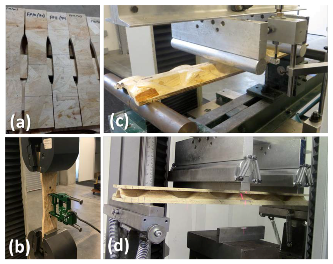
4. Finite Element Model
To evaluate the bending behavior of both the sandwich panel and the corrugated core within the elastic region, FE models were developed using Abaqus finite element software (
Figure 4). For both the flat outer layers and the core, shell elements (S4R) with hourglass control and a reduced integration rule were employed. To easily assign material orientation to the core with complex geometry, a shell element was chosen. Since this type of element considerably decreases the simulation and running time of the FE model, a finer mesh was adopted to increase the accuracy. In addition, all elements were given the capability to undergo finite strains and rotations.
Considering the fabrication process, both the corrugated core and the flat outer plies were assumed to be transversely isotropic. To simulate a perfect bond between the face-sheets and the 3-D core, rigid links were modeled between the nodes of these two components using a tie constraint. As for the boundary conditions, the nodes in the contact area between the specimens and the supports were constrained in the
z direction. Since the supports were free to rotate about the
y axis to be consistent with ASTM D7249 [
22], no other boundary condition was applied. However, to avoid instability in the structure, the centerline of the sandwich panel exactly at the mid-span was fixed to avoid any translation in the
x direction. Loading was applied as prescribed downward deflection of the loading heads.
To determine an acceptable element size, a mesh convergence analysis was performed on the flexural 3-D core model. In
Figure 5, the results of this convergence study are displayed, comparing the bending load that corresponds to a deflection of 25.4 mm in the center of the specimen to the number of elements. As the number of elements increased from 4263 to 59,814 (corresponding to an element size of 5 mm to 1.3 mm), there was a 1.73% change in the resulting bending load. Because of this negligible change in the bending load and noticeable savings in the computation time, the smallest number of elements considered, 4263 (element size of 5 mm), was chosen to mesh the specimens.
5. Theoretical Model
Due to the complex geometry of a biaxially corrugated core with cavities caused by three-dimensional geometry, it is not easy to develop a theoretical model to capture all deformations under different types of loading. One method to overcome this difficulty is homogenization. In this section, the inhomogeneous sandwich panel with corrugated core geometry is replaced with an equivalent homogenous and continuous layer. The effective properties for this homogenous and continuous layer consist of effective extensional moduli in the
x and
y directions, effective Poisson’s ratio, and effective shear modulus in the
x–
y plane. Because it is a common practice to compute these effective properties with only consideration of in-plane loading [
23,
24,
25], they were calculated based on the laminate extensional stiffness matrix, generally referred to as the [
A] matrix. Besides the assumption of neglecting resultant moments to calculate effective properties, in developing the theoretical model, all stresses through the thickness were also neglected. Additionally, the [
A] matrix components were computed by integrating over the UC volume instead of UC height.
The constitutive equation for a laminate in terms of resultant forces [
N], resultant moments [
M], mid-plane strains {
ε0}, and mid-plane curvatures {κ} can be written as
where
A,
B, and
D are the extensional stiffness, the bending–extension coupling, and the bending stiffness matrices, respectively, and their components are defined as
The symmetric and balanced configuration of the sandwich panel about its mid-plane results in a zero bending–extension coupling matrix, [
B] (see
Appendix A). In addition, because the sandwich panel was assumed to be a simplified 2-D structure and evaluated like a plate, all stresses through the thickness were neglected. Therefore, the constitutive equation for the sandwich panel is defined [
23] as
and the components of the extensional stiffness matrix ([
A]) given in Equation (2) expanded over three layers can be rewritten as
where
Qij are components of the stiffness matrix in the global coordinate system (
x–y–z) [
26]. Additionally,
hf is the thickness of the outer layers and
hc is the height of the corrugated core. For uniaxial corrugated cores, such as those with sinusoidal or trapezoidal configurations where the corrugated geometries can be easily specified with a known function, computing these integrals over the height to calculate the extensional stiffness matrix ([
A]) is straightforward [
27,
28,
29]. However, since the geometry of the core analyzed in this study is biaxially corrugated and varies along both the
x and
y axes, the second term in Equation (7) representing the core layer cannot be easily computed. Unlike other methods which use a known function describing the core geometry to compute Equations (5) and (7), a discretization technique was used to simplify the integration in this study. Therefore, one quarter of the UC (
Figure 2b) was broken down into seven simplified domains as shown in
Figure 2b. Subsequently, integration was carried out over the simplified domains and averaged as
where
L1 and
L2 are dimensions of the unit cell, and
Vk is volume of each domain shown in
Figure 2b.
It should be noted that the components of the global stiffness matrix (
Qij) of the core layer given in Equations (7) and (8) are obtained by transforming the stiffness matrix in the local coordinate system (1–2–3) using the transformation matrix, [
T]. Considering the global coordinate system (
x–y–z) and local coordinate system (1–2–3) that varies from domain to domain, the transformation matrix for each domain is expressed as
and inverting the extensional stiffness matrix ([
A]) in Equation (6) results in
The stress-strain relation for a homogenous and continuous lamina with the thickness of
h is expressed as
and comparing Equation (10) for the biaxial corrugated core sandwich panel with Equation (11) for a lamina gives the effective material properties of a lamina that is equivalent to the biaxial corrugated core sandwich panel. These material properties are summarized [
23] as
Considering these effective material properties, two different beam models, classical beam theory (Euler–Bernoulli) and first-order shear deformation beam theory (Timoshenko), were employed to investigate the bending behavior of the equivalent structure. Using displacement fields of these beam models, the principle of minimum potential energy, and the variational method, the governing equations for this sandwich beam [
30,
31] were derived as
where beam deflection and rotation of the cross section about the
y axis with respect to the thickness direction are shown with
w and
respectively. Additionally,
and
,
,
A, and
I, which are components of the stiffness matrix of the homogenized beam, shear correction factor, cross section area, and moment of inertia, respectively, are given as
As shown in
Table 1,
b and
h are the width and the height of the sandwich panel test specimen and the material properties are given in Equation (12). It should be noted that effective out-of-plane shear modulus (
G13) is assumed equal to that of in-plane shear modulus (
G12) [
23]. Since Fourier series expansions satisfy the boundary conditions [
32], they were used to solve the governing equation(s). Based on Euler–Bernoulli and Timoshenko beam theories, the closed form solution for the deflection of this sandwich beam with biaxial corrugated geometry under a four-point bending test, as shown in
Figure 4, is obtained as:
7. Sensitivity Analysis
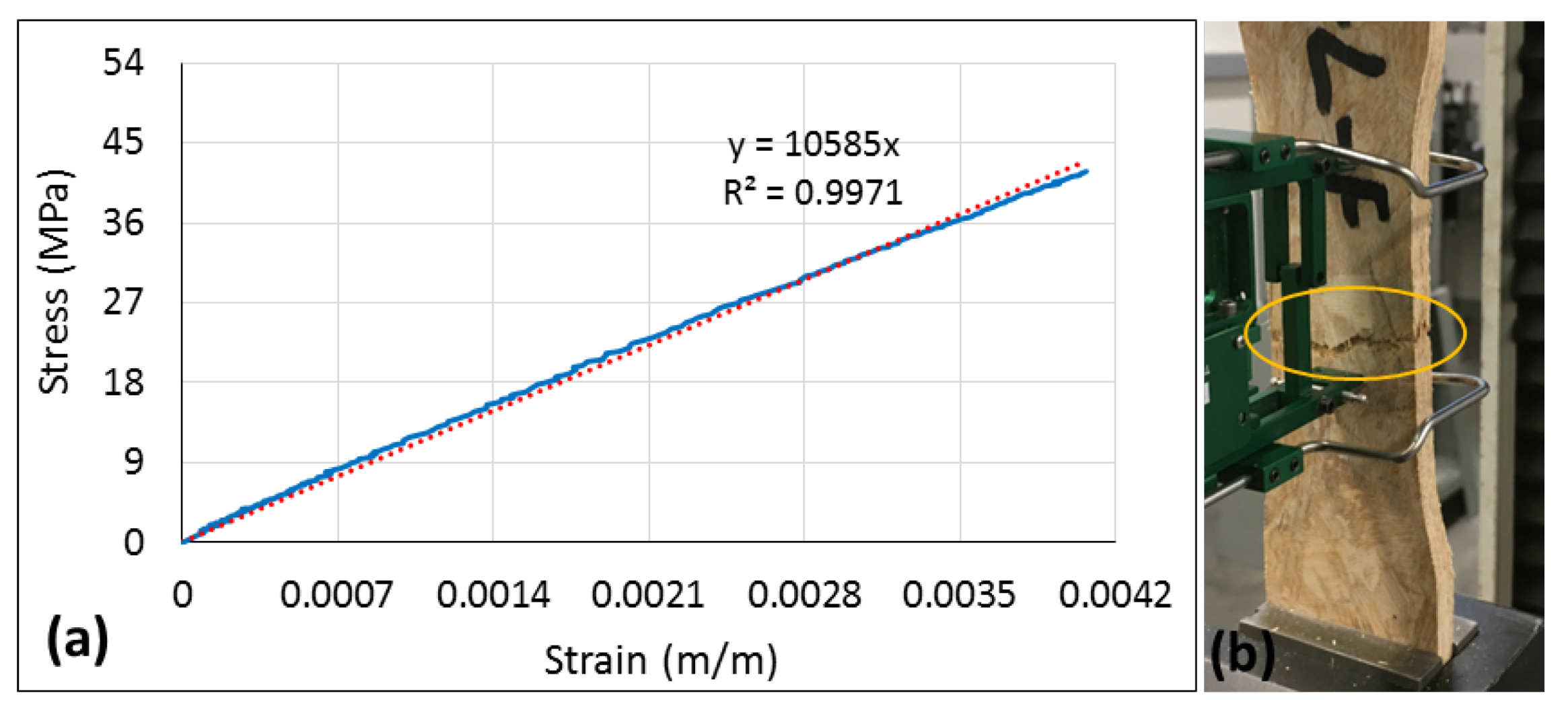
Intrinsic variation in material properties of wood strands, inconsistencies in the fabrication process, and variations in density may influence the material properties of the wood strand composite panels, as shown in the results so far. Even with extreme care during the fabrication process and the testing, there still will be noticeable variation in the material properties determined (reflected by the coefficient of variations in
Table 2). Such a variation leads to variation in the bending stiffness of the sandwich panel and its components. In this section, a sensitivity analysis is presented to clarify the extent of variation in bending stiffness that could be expected due to specified variation in material properties. To this end, using the FE simulation and theoretical model, one material property was changed while others were held constant, and then change in the bending stiffness of the sandwich specimen due to change in the material property was obtained. The coefficient of variation (COV) for each property listed in
Table 2 was used as a guide to vary a material property to perform the sensitivity analysis. Results of the sensitivity analysis are given in
Table 4. Based on COVs listed in
Table 2, e.g., the longitudinal Young’s modulus (
E1) was varied by ±9.4%, and the bending stiffness was computed using FE and theoretical models. A 9.4% increase in
E1 indicates an increase of 8.5%, 9.3%, and 9.2% in FE, Euler–Bernoulli, and Timoshenko bending stiffness, respectively. Meanwhile, a 9.4% reduction in
E1 shows a decrease of 8.7%, 9.2%, and 9.1% in FE, Euler–Bernoulli, and Timoshenko bending stiffness. However, a higher change in
E2, ±13.4%, creates less than ±1% change in both FE and the theoretical bending stiffness. Theoretical bending stiffness is not as sensitive as that of FE to change in shear modules because the effects of shear stresses and deformation through the thickness of the panel to calculate effective properties, which were used to develop the theoretical model, were neglected.
8. Conclusions
Theoretical and finite element models were developed and applied to predict the linear flexural behavior of the sandwich panel with a complex three-dimensional core geometry manufactured from small-diameter timber under a four-point bending load. The material properties were measured to input into the models.
The bending stiffness of just the corrugated core specimens obtained by the FE model showed a 1.4% difference from the average of the experimental results. In case of the sandwich panel, the average experimental bending stiffness differed from Euler-Bernoulli, Timoshenko, and FE predictions by 3.6%, 5.2%, and 6.5%, respectively. The results indicated that a 46% increase in material density increases the longitudinal Young’s modulus by as much as 107%. A sensitivity analysis to understand the effect of variations in material properties on composite sandwich bending stiffness revealed that the longitudinal Young’s modulus is the most important property that influences the bending stiffness.
Theoretical and FE models developed for the wood strand sandwich panel were utilized to conduct a parametric study [
33] to understand the influence of the core geometry on the bending stiffness of the sandwich panel. Based on the results, new core geometry with higher performance was designed to meet the structural performance requirements of building envelope components, such as wall, floor, and roof. Theoretical models for the sandwich structure with new core geometry were developed for beam [
34] and plate [
35] configurations.


