Abstract
Structural complexity of trees is related to various ecological processes and ecosystem services. To support management for complexity, there is a need to assess the level of structural complexity objectively. The fractal-based box dimension (Db) provides a holistic measure of the structural complexity of individual trees. This study aimed to compare the structural complexity of Scots pine (Pinus sylvestris L.) trees assessed with Db that was generated with point cloud data from terrestrial laser scanning (TLS) and aerial imagery acquired with an unmanned aerial vehicle (UAV). UAV imagery was converted into point clouds with structure from motion (SfM) and dense matching techniques. TLS and UAV measured Db-values were found to differ from each other significantly (TLS: 1.51 ± 0.11, UAV: 1.59 ± 0.15). UAV measured Db-values were 5% higher, and the range was wider (TLS: 0.81–1.81, UAV: 0.23–1.88). The divergence between TLS and UAV measurements was found to be explained by the differences in the number and distribution of the points and the differences in the estimated tree heights and number of boxes in the Db-method. The average point density was 15 times higher with TLS than with UAV (TLS: 494,000, UAV 32,000 points/tree), and TLS received more points below the midpoint of tree heights (65% below, 35% above), while UAV did the opposite (22% below, 78% above). Compared to the field measurements, UAV underestimated tree heights more than TLS (TLS: 34 cm, UAV: 54 cm), resulting in more boxes of Db-method being needed (4–64%, depending on the box size). Forest structure (two thinning intensities, three thinning types, and a control group) significantly affected the variation of both TLS and UAV measured Db-values. Still, the divergence between the two approaches remained in all treatments. However, TLS and UAV measured Db-values were consistent, and the correlation between them was 75%.
1. Introduction
Forest structure refers to all dimensional, architectural, and distributional features of tree individuals in a given space at a given time [1,2]. The structure of a tree is influenced by its genetics and biotic and abiotic external factors. Forest management causes trees to allocate their growth differently, affecting the forest structure [3,4]. Forest structure is an important driver of several ecosystem functions and services [5], and forest structural complexity has been noticed to correlate, for example, with biodiversity [6], scenic beauty and recreational benefits [7], micro-climatic stability [8], and forest productivity [9]. In addition, structural complexity enhances ecosystem carbon storage [10] and the ability of forests to adapt to environmental changes [11]. To support forest management, the forest structural complexity must be measured objectively.
Traditionally, structural complexity has been measured with different indices, which use different subsets of one- or two-dimensional (2D) structural attributes. For example, the structural complexity index [12] utilizes tree height and spacing, while the tree size differentiation index [13] utilizes diameter and spacing [8]. Nowadays, forest structure can be examined holistically with three-dimensional (3D) data derived from different remote sensing systems [1,8,14].
Especially terrestrial laser scanning (TLS) has shown to be an efficient method for assessing the 3D forest structure [14,15,16,17,18]. TLS is an active remote sensing system that uses LiDAR (light detection and ranging) to measure the surrounding 3D space with millimeter-level accuracy [19]. Basically, the structural complexity can be assessed whenever the point cloud data is available. In addition to scanning LiDAR systems, point clouds can be generated from images using photogrammetric methods. For example, structure from motion (SfM) technology creates a 3D structure of a target by utilizing overlapping 2D imagery taken from multiple viewpoints [20]. For finding correspondence between images, different object recognition systems are used. Usually, a corresponding feature must appear on at least three images but obtaining as many images as possible is recommended for redundancy [20]. The matching features are then tracked and used to estimate the camera positions and orientations [20,21]. For example, aerial imagery for SfM purposes can be acquired with unmanned aerial vehicles (UAV).
TLS and UAV photogrammetry is widely used in examining 3D forest structure [22], and both have advantages and disadvantages. TLS produces denser and more detailed point clouds than UAVs [23,24,25]. However, aerial images can be acquired with consumer-grade UAVs, digital cameras, and open-source software [16,20], which reduces costs. In addition, the TLS approach is rather laborious and time-consuming due to equipment transport and displacement in potentially challenging conditions [26] and the measuring and co-registration of multi-scan point clouds [16]. Although the operational area of a UAV is limited by battery duration [22], airborne data acquisition is quicker and allows larger area coverage than TLS. Due to the limited field of view and occlusion caused by other trees, the ability of TLS to capture the upper canopy can be limited [27,28]. In contrast, the measurement geometry of UAVs is limited precisely to the upper canopy surface [29]. As a passive remote sensing system, aerial photography cannot penetrate the canopy at the same level as active systems. Therefore, mid- and understory might remain poorly defined with the UAV approach [21,30].
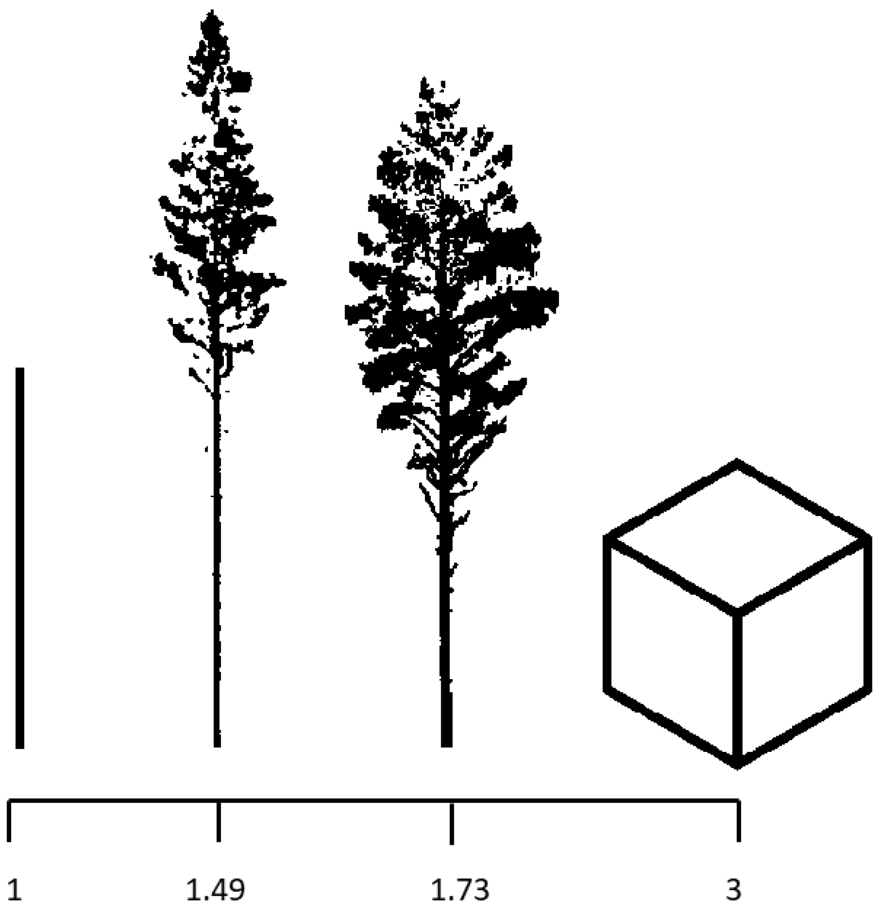
Object structural complexity can be mathematically described by fractal analysis [31]. With the recent 3D data, it has become possible to utilize fractal analysis to determine the structural complexity of trees. A fractal-like nature of a crown is an essential aspect of a tree’s structure [32]. Fractals are self-similar geometric objects, that is, objects that are formed of small parts that each resemble the whole [33]. Due to external and internal factors, trees are not perfectly self-similar [34] but only fractal-like. Box dimension (a.k.a. Minkowski–Bouligand dimension) is a method for estimating the complexity of fractal-like objects [32,33]. For a tree, box dimension (Db) values can theoretically vary between 1 and 3, where 1 would be a branchless pole and 3 a solid cube [35]. Figure 1 shows two trees with a Db-value between these extremes. According to the earlier studies, the physical limit for a tree is somewhere near two, but trees growing in open or urban areas can reach higher values [35,36].
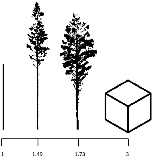
Figure 1.
Illustration of objects with different box dimension (Db) values: a pole (Db = 1), two structurally different Scots pine trees (Db = 1.49 and 1.73), and a cube (Db = 3). Modified after Figure 1 in Seidel [35].
Box dimension provides a holistic measure of the structural complexity related to tree ecological functions and services [5]. When the level of structural complexity can be measured, it can be enhanced with silvicultural choices. Trees develop a certain structure to maximize the resources they need for growth, and the box dimension deepens our understanding of how the structure and function of trees are connected. It gives an insight into the balance between construction and maintenance costs on the one hand and photosynthetic gains on the other by describing the structural efficiency, productivity, and crowing conditions (i.e., competition, availability of light) [2,32,35,37]. Db measures the density and distribution of plant material and simultaneously reflects several structural attributes (e.g., crown dimensions, branching patterns) [2,34]. A point cloud’s architectural information is combined into a single number [5]. However, this makes it difficult to distinguish which aspect affects the complexity [35], and the direct comparison with other measurement approaches remains uncertain [32]. In addition, as the box dimension of a tree is nearly impossible to measure in field inventories, there is no direct reference data. Hence, it is important to understand how different remote sensing techniques measure box dimension values and whether these techniques are comparable.
In recent years, the box dimension method has been increasingly used to measure individual trees’ structural complexity. It has been related, for example, to tree species identification, availability of light [32], type and strength of competition [32,34], benefit-to-cost ratio (i.e., the ratio between photosynthetically active surface and the volume of the “wooden skeleton”) [35], and tree growth [4].
Box dimension values have mainly been calculated from LiDAR-based point cloud data, while photogrammetric methods have received less attention. Our study bridges this knowledge gap as the aim is to assess the structural complexity of individual Scots pine trees by comparing TLS and UAV photogrammetry (hereafter referred to only as UAV). TLS and UAV provide different perspectives for examining structural complexity; thus, the calculated box dimension values may differ. In order for both methods to be used as a basis for Db-values, it is important to know the level of comparability between them and to understand what causes the possible differences. The research questions are: (1) Do TLS and UAV measured box dimension values differ significantly from each other? (2) what explains the possible divergence between the values? and (3) does the forest structure influence the divergence between TLS and UAV measurements? The hypotheses are that (1) the differences in the number and distribution of the points in the TLS and UAV measured point clouds explain the divergence between the values, (2) the differences in the estimated tree heights and number of boxes explain the divergence, (3) the sparser the forest, the better UAV measurements correspond to TLS, and (4) structurally complex trees are characterized as complex by both methods.
2. Materials and Methods
2.1. Study Area
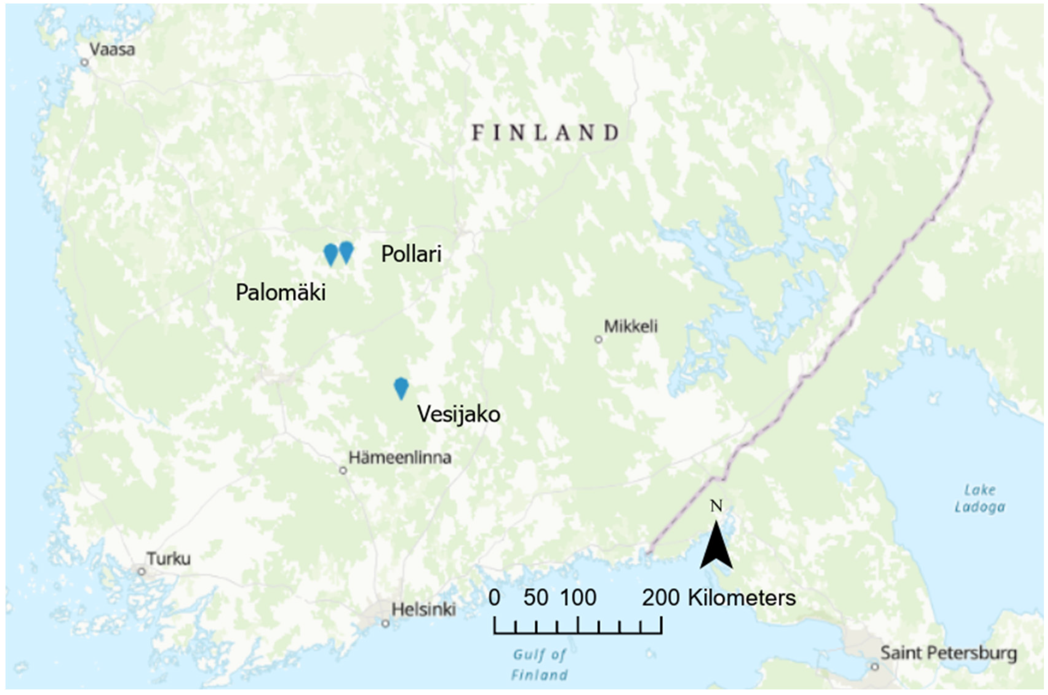
The study area consists of three study sites with nine rectangular 900–1200 m2 sample plots in each. The sites have been originally described by Saarinen et al. [3,4] and Yrttimaa et al. [28,38]. The Natural Resources Institute Finland established the study area in 2005–2006 to investigate the effect of different thinning treatments on Scots pine (Pinus sylvestris) trees. The sites are located in southern Finland (Figure 2), the biome is the southern boreal forest zone, and the fertility is mesic heath. Even-aged Scots pine trees dominate all sites. More detailed information on the study sites is presented in Table 1.
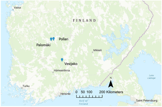
Figure 2.
Location of the study sites: Palomäki, Pollari, and Vesijako.

Table 1.
Information on the study sites.
The first thinning was executed in the early 1990s (~30% of stems removed), and during the 2000s, the study sites were exposed to six different thinning treatments plus one control group with no treatment. Thinning treatments included two levels of thinning intensity (moderate, intensive) and three thinning types (from below, from above, systematic from above) (Table 2).

Table 2.
Different thinning treatments.
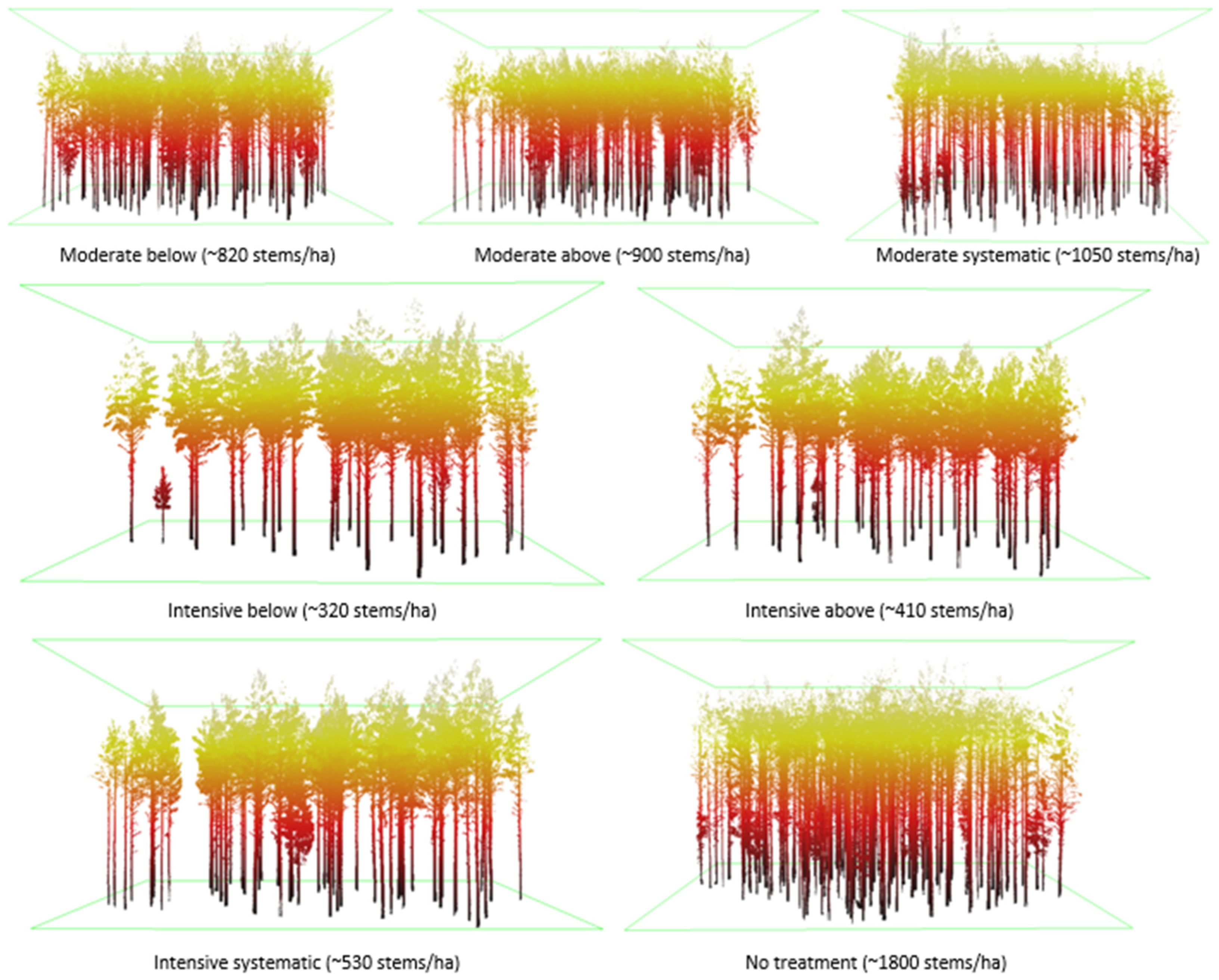
Small, suppressed, and damaged were removed in thinning from below and thinning from above. In thinning from below, co-dominant trees were removed, whereas mostly dominant trees were removed in thinning from above. In systematic thinning, only dominant trees were removed while suppressed and co-dominant trees were left to grow. Regular spatial distribution of trees was maintained in thinnings from below and above, while in systematic thinning, it was not emphasized as much. The remaining basal area after moderate thinning was ~68% of stocking before treatment and after intensive thinning ~34%. Figure 3 illustrates the effects of different thinning treatments on stand density.
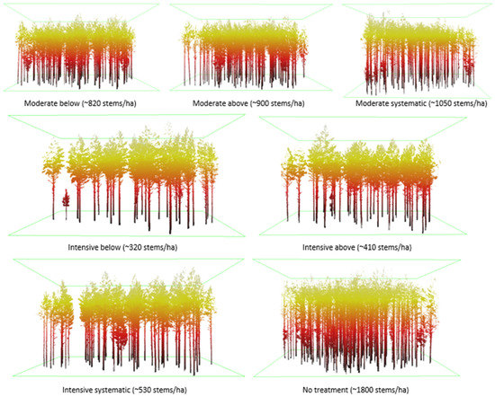
Figure 3.
Illustration of different thinning treatments based on processed terrestrial laser scanning (TLS) data. Tree density (stems/ha) includes all tree species.
Tree-wise field inventory was carried out during 2018–2019, and for all trees, tree species, diameter at breast height (DBH), crown layer, and health status were recorded. Roughly half of the trees were selected as sample trees for which tree height, crown base height, and the height of the lowest dead branch were recorded with an electronic clinometer. The heights of the other trees were estimated with allometric models calibrated for each plot using the sample trees. In total, there were 2203 trees in the study area: 2107 Scots pines, 90 Norway spruces (Picea abies), 4 grey alders (Alnus incana), and 2 downy birches (Betula pubescens). Accordingly, the portion of Norway spruce was 4.1%, and the portion of deciduous trees was 0.3%.
2.2. Point Cloud Data Acquisition
Acquisition of the point cloud data used in this study has been originally described in Saarinen et al. [3,4] and Yrttimaa et al. [28,38]. TLS data were obtained between September and October 2018 using a multi-scan approach and a Trimble TX5 3D phase-shift laser scanner (Trimble Inc., Sunnyvale, CA, USA) operating at a 1550 nm wavelength and measuring 976,000 points per second. The scanner delivers a hemispherical (300° vertical, 360° horizontal) point cloud with an angular resolution of 0.009° in both vertical and horizontal directions. These scanning parameters resulted in a point spacing of approximately 6.3 mm at 10 m distance from the scanner in an individual TLS point cloud. Each sample plot was scanned from eight scan positions evenly distributed on the sample plot to obtain a comprehensive characterization of each of the 27 sample plots. Two scans were conducted from the plot center and six scans closer to the plot borders. The scanner was placed on a tripod at a height of ~1.7 m from the ground. Artificial reference targets (i.e., white spheres of 198 mm in diameter) were used for co-registering the scans into one coordinate system. The registration was implemented using FARO SCENE software (version 2018) with a mean distance error of 2.9 ± 1.2 mm, mean horizontal error of 1.3 ± 0.4 mm, and mean vertical error of 2.3 ± 1.2 mm. The average point density of the multi-scan point clouds was 52,000–91,000 points/m2, depending on the sample plot structure.
UAV point clouds were acquired in October 2018 using Gryphon Dynamics quadcopter equipped with an Applanix APX-15 EI UAV positioning system consisting of a multiband GNSS and IMU, a Harxon HX-CHX600A antenna, and two Sony A7R II digital cameras (CMOS sensors of 42.4 MP with Sony FE 35 mm f/2.8 ZA Carl Zeiss Sonnar T* lenses). The cameras were mounted at +15° and −15° oblique zenith angles to improve the 3D digitization of trees [40] and the inclusion of more ground control points (GCPs) [41]. Images were acquired every two seconds and triggered via Sony Timelapse software to record precise positions and orientation angles for each captured image. Post Processed Kinematic (PPK) GNSS solutions and angles for each camera were computed in an Applanix POSPac UAV (version 8.2, Applanix, Richmond Hill, ON, Canada) software, using a RINEX service of the National Land Survey of Finland, which offers observation data from the FinnRef stations. During the UAV campaign, the flying altitude was 140 m and the speed was 5 m/s.
The number of captured images was 639 (Palomäki), 614 (Pollari), and 663 (Vesijako). The imaging forward overlap was ~90%, and the side overlap was ~80%. Eight GCPs were placed and measured for each study site using the Topcon Hiper HR RTK GNSS receiver (Topcon, Tokyo, Japan). The photogrammetric processing was carried out using the Agisoft Metashape software (version 1.5.0) following the workflow presented by Viljanen et al. [42]. The photogrammetric UAV point clouds were generated from images with two-times magnified pixel size (i.e., using the quality setting ‘high’). A depth filtering (with the setting ‘mild’) was applied for the resulting point clouds to reduce erroneous points while retaining small features of interest as much as possible, such as treetops [41,43]. In the bundle adjustment, the root mean square errors (RMSEs) of GPCs were 0.29–1.75 cm for the x-, y-, and z-coordinates (Table 3). As a result, the dense UAV point clouds were obtained with a reprojection error of 0.65–0.70 pixels, point cloud resolution of 3.11–3.53 cm/pixel, and a point density of 804–1030 points/m2, depending on the study site.

Table 3.
The average root mean square errors (RMSEs) of ground control points (GCPs) for x-, y- and z-coordinates in each study site.
TLS and UAV point clouds were normalized using LAStools software [44]. TLS point cloud normalization followed the procedure and parameters initially presented in Ritter et al. [45]. This included classifying the point cloud into ground points and vegetation points. The ground points were used to generate a digital elevation model (DTM), which was used to convert the z-coordinates of vegetation points into heights above the ground. In the case of UAV point clouds, the normalization was carried out with a DTM provided by the National Land Survey of Finland.
Due to differences in the applied coordinate reference systems (CRSs), the normalized TLS (scanner’s local CRS) and UAV point clouds (global CRS) were registered together by manually searching for common tie points and carrying out a 3D rigid transformation between the datasets. Manually extracted locations of the tops of sample trees (minimum of 4 per each sample plot) were used as the tie points for the coordinate transformation. The sample trees were selected to completely characterize their crown structure in TLS and UAV point clouds. The top locations were determined by picking the highest point representing the top of each sample tree. The coordinate pairs (i.e., TLS-derived and UAV-derived tree top location) were used to compute a 3D rigid transformation matrix that was then used to transform the TLS point cloud into the UAV point cloud’s CRS. Canopy height models (CHMs) at a 20 cm resolution were then generated from the normalized point clouds. Treetop positions were identified with the Variable Window Filter approach [46], and crown segments were delineated with Marker-Controlled Watershed Segmentation [47]. The crown segments were then used to extract TLS and UAV points of individual trees. Prior to further analyses, TLS points classified as ground points and UAV points with a height close to zero were omitted. The workflow of the point cloud data processing is presented in Table 4.

Table 4.
Workflow of terrestrial laser scanning (TLS) and unmanned aerial vehicle (UAV) measured point cloud data processing. DTM = digital terrain model, CRS = coordinate reference systems, CHM = canopy height model, R = statistical software R.
2.3. Methods
The box dimension (Db) of a tree is determined by counting how many cubic boxes are needed to cover all the points in the 3D point cloud and how the number of boxes changes when the box size changes [35]. The counting starts with the largest box needed to cover the whole tree (edge length = tree height) and proceeds with smaller boxes, always having half the edge length of the previous box [34,37]. The calculation has the following steps described by Feldman [33]:
1. count the number of boxes needed to cover the object (N);
2. repeat with smaller box sizes (r = length of the box edge/length of the largest box edge);
3. collect the values of N and 1/r into a table;
4. take the logarithm of the values;
5. plot the data with log(N) on the vertical axis and log(1/r) on the horizontal axis;
6. Db is then the slope of the trendline.
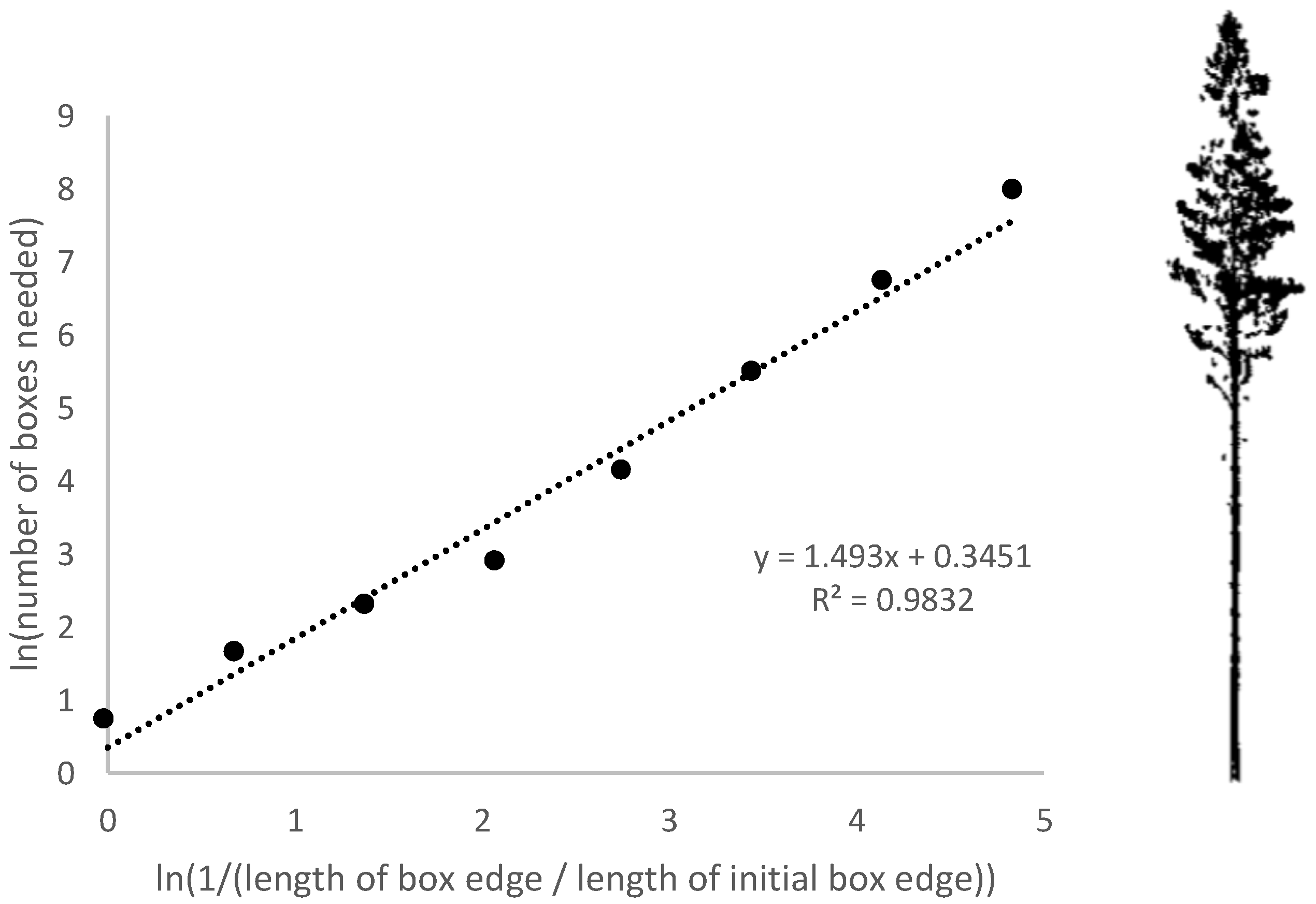
In this study, the box dimension for each detected tree was calculated from TLS and UAV measured point clouds using statistical software R (version 4.0.2). Only trees detected with TLS and UAV were included in this study, so the sample size was 2065. Eight box sizes were used so that the edge length of the initial box corresponded to tree height, and the following box sizes were tree height divided by 2, 4, 8, 16, 32, 64, and 128. The values were calculated with natural logarithms. Figure 4 exemplifies the process: the eight points on the graph represent the calculations with eight different box sizes, and the slope of the fitted straight line expresses the Db-value.
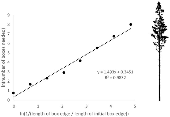
Figure 4.
Box dimension (Db) is the slope of the fitted straight line (x = 1.493). Modified after Figure 1 in Seidel [32].
The means of TLS and UAV measured Db-values were compared with Welch’s t-test. To understand the statistical dispersion, point clouds were examined with standard deviation. The correlations between TLS and UAV measured Db-values, and the number of points was tested with the Pearson correlation test. The differences between the ranges of TLS and UAV measured x-, y- and z-axes were examined by subtracting UAV ranges from TLS ranges. Furthermore, the distributions of TLS and UAV measured points were examined by dividing trees longitudinally into two equal parts and calculating the proportion of points below and above. Simple linear regression was used to examine whether the number of TLS and UAV measured points explained the variation in Db-values and whether the number of the boxes explained the variation in Db-values. A linear mixed-effect model was used to examine whether different thinning treatments affected the Db-values. p-values below 0.05 were considered statistically significant. Tests were executed with either R or SPSS Statistics software (version 27). Figures of point clouds were created with CloudCompare software (version 2.11.1) or with the lasview tool from LAStools software [44].
3. Results
3.1. Tree Detection
Out of all 2107 Scots pine trees identified during the field measurements in the study area, TLS detected 2075 trees and UAV 2065. TLS therefore missed 32 trees (1.5%) and UAV 42 (2.0%). In the sparsest plots (intensive below, 286 trees/ha), all the Scots pine trees were detected, and in the densest plots (no treatment, 1315 trees/ha), the detection rate was the weakest: 96–97% (Table 5).

Table 5.
Tree density, including all tree species, number of undetected Scots pine trees by terrestrial laser scanning (TLS) and unmanned aerial vehicle (UAV), and detection rates within different thinning treatments.
3.2. Box Dimension Values
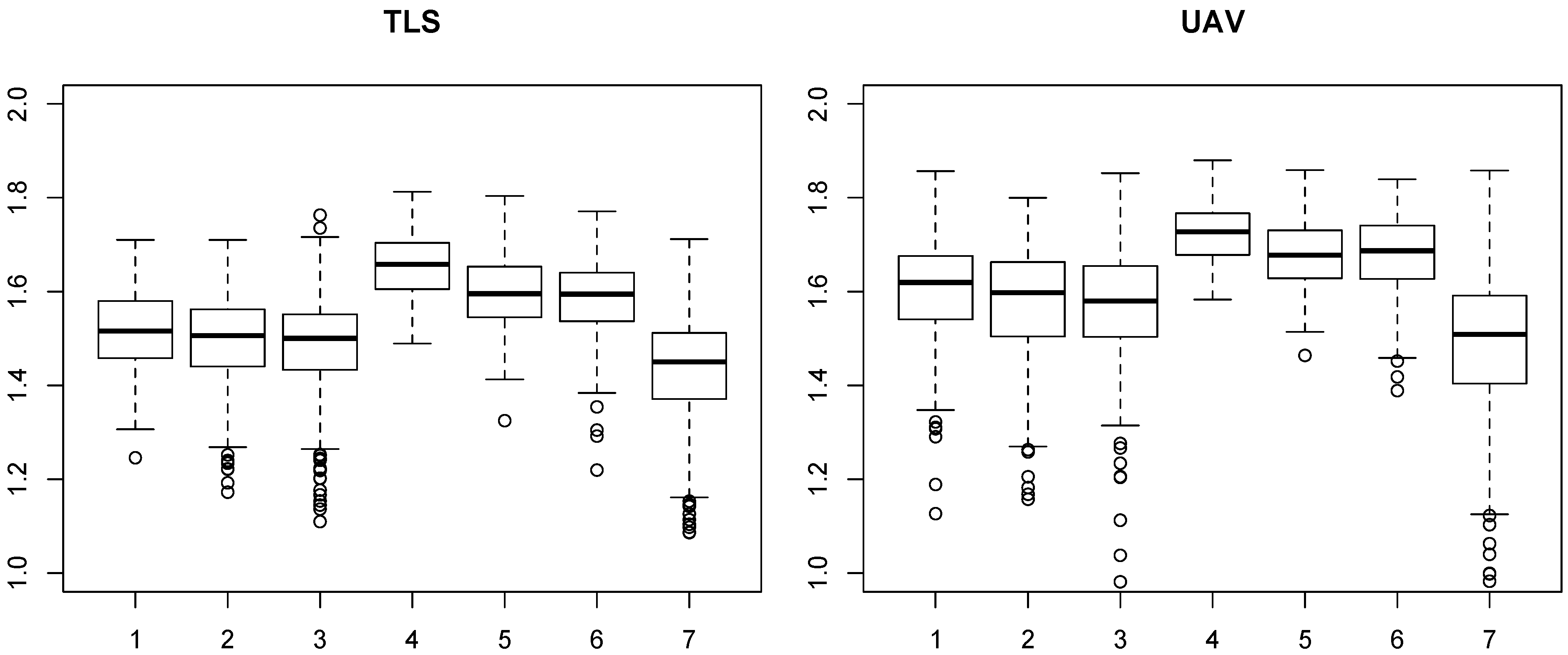
The means and standard deviations of TLS and UAV measured Db-values for all plots were 1.51 ± 0.11 and 1.59 ± 0.15, respectively. The range for TLS measured values was 0.81–1.81 and for UAV 0.23–1.88. Other descriptive statistics within different thinning treatments are shown in Table 6. Db-values were higher in the intensive thinning treatments than in moderate thinnings and lowest in the control plots. According to the thinning type, the order of Db-values from highest to lowest is below, above, and systematic. Figure 5 demonstrates how TLS and UAV measured Db-values vary in thinning treatments.

Table 6.
Means (with standard deviations, ±), minimums, maximums, and ranges of terrestrial laser scanning (TLS) and unmanned aerial vehicle (UAV) measured box dimension (Db) values within different thinning treatments.
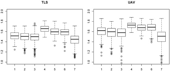
Figure 5.
Boxplots of terrestrial laser scanning (TLS, left) and unmanned aerial vehicle (UAV, right) measured box dimension (Db) values (y-axis) within different thinning treatments (x-axis). Treatment numbers are explained in Table 2.
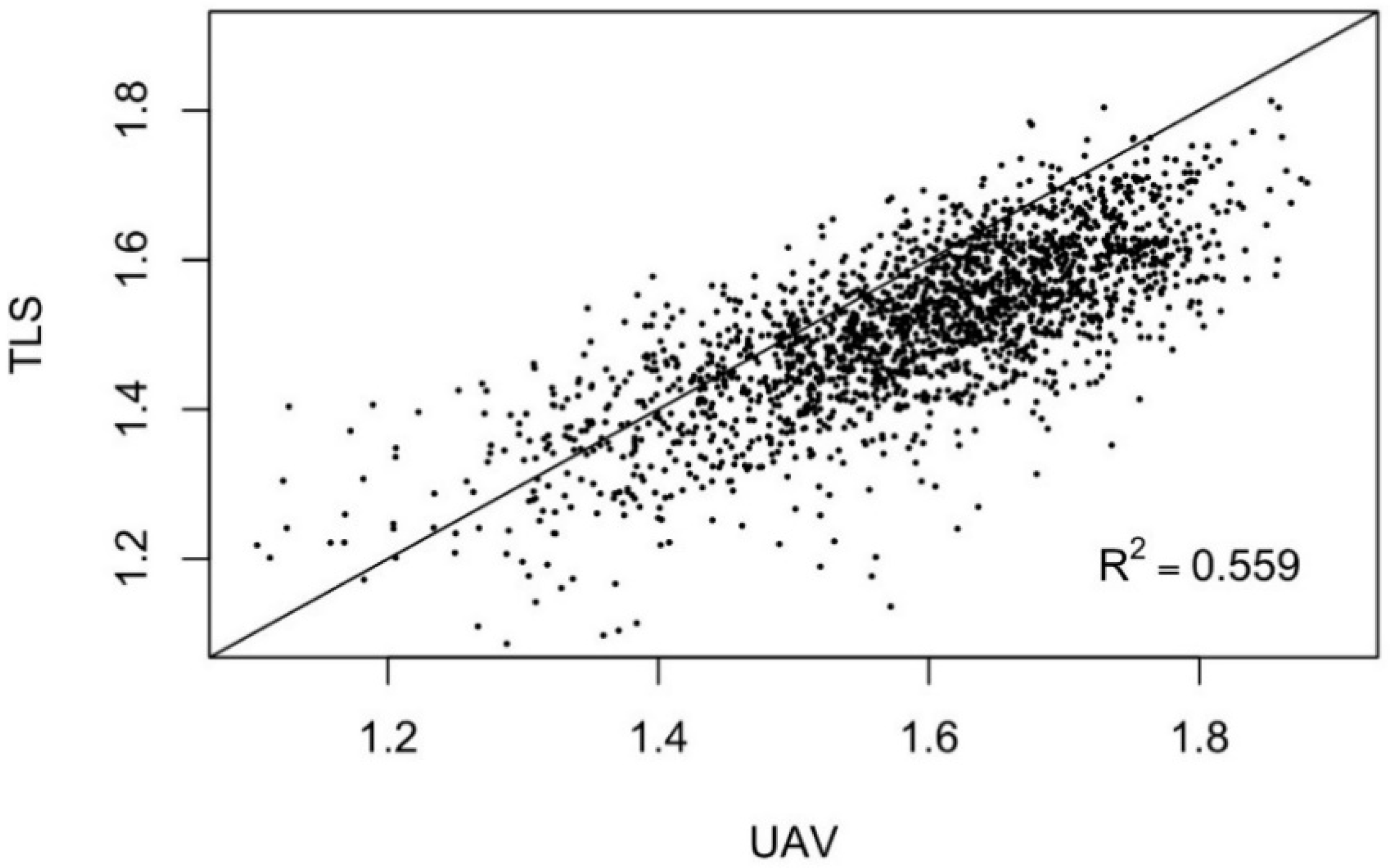
TLS and UAV measured Db-values differed significantly from each other (p-value < 0.001), and on average, UAV measured Db-values were 5% higher than TLS measured. A linear mixed-effects model was used to examine whether different thinning treatments affected Db-values. It was found that forest structure significantly affected both TLS and UAV measured Db-values (p-values < 0.001). However, in every treatment, the divergence between the TLS and UAV measured Db-values was statistically significant (p-values < 0.001). The correlation between TLS and UAV measured Db-values was 75%, and the coefficient of determination (R2) was 56% (Figure 6).
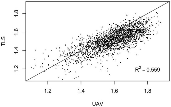
Figure 6.
Relationship between the box dimension (Db) values measured with terrestrial laser scanning (TLS) and unmanned aerial vehicle (UAV). The coefficient of determination (R2) is 0.559.
3.3. Number and Distribution of Points
The average point density for all plots with TLS was 494,000 points/tree, and with UAV, 32,000 points/tree. For both TLS and UAV, the highest point densities were obtained from the plots with intensive thinnings and the lowest from the control plots (Table 7). In addition, with TLS and UAV, high point densities and high Db-values occurred together, and the correlation between the number of measured points and Db-values was 52% with TLS and 71% with UAV.

Table 7.
Means of terrestrial laser scanning (TLS) and unmanned aerial vehicle (UAV) measured box dimension (Db) values and average point densities/ tree in thousands (K) (with standard deviations, ±) within different thinning treatments.
It was further examined whether the number of UAV points affected the difference of the means in TLS and UAV measured Db-values. That is, are the means similar when more UAV points are obtained? To test this, trees were divided into five classes according to how many UAV measured points they contained (Table 8). In every class, the differences between the means in TLS and UAV measured Db-values were statistically significant (p-values < 0.001).

Table 8.
Detected Scots pine trees (n = 2065) are divided into five classes according to the number of measured points of unmanned aerial vehicles (UAV). The average number of terrestrial laser scanning (TLS) measured points in each class was consistent with UAV points.
The distribution of the points was examined by dividing trees in half with respect to the z-axis (i.e., longitudinally) and calculating points above and below (Table 9). On average, 65% of TLS measured points originated below and 35% above the midpoint of tree heights. With UAV, the percentages were 22% below and 78% above. The largest difference between TLS and UAV measurements was found in the control plots. With the intensive thinnings, TLS and UAV measured above and below percentages were closest to each other.

Table 9.
Percentages of terrestrial laser scanning (TLS) and unmanned aerial vehicle (UAV) measured points above and below the midpoint of the z-axis (i.e., the height of trees).
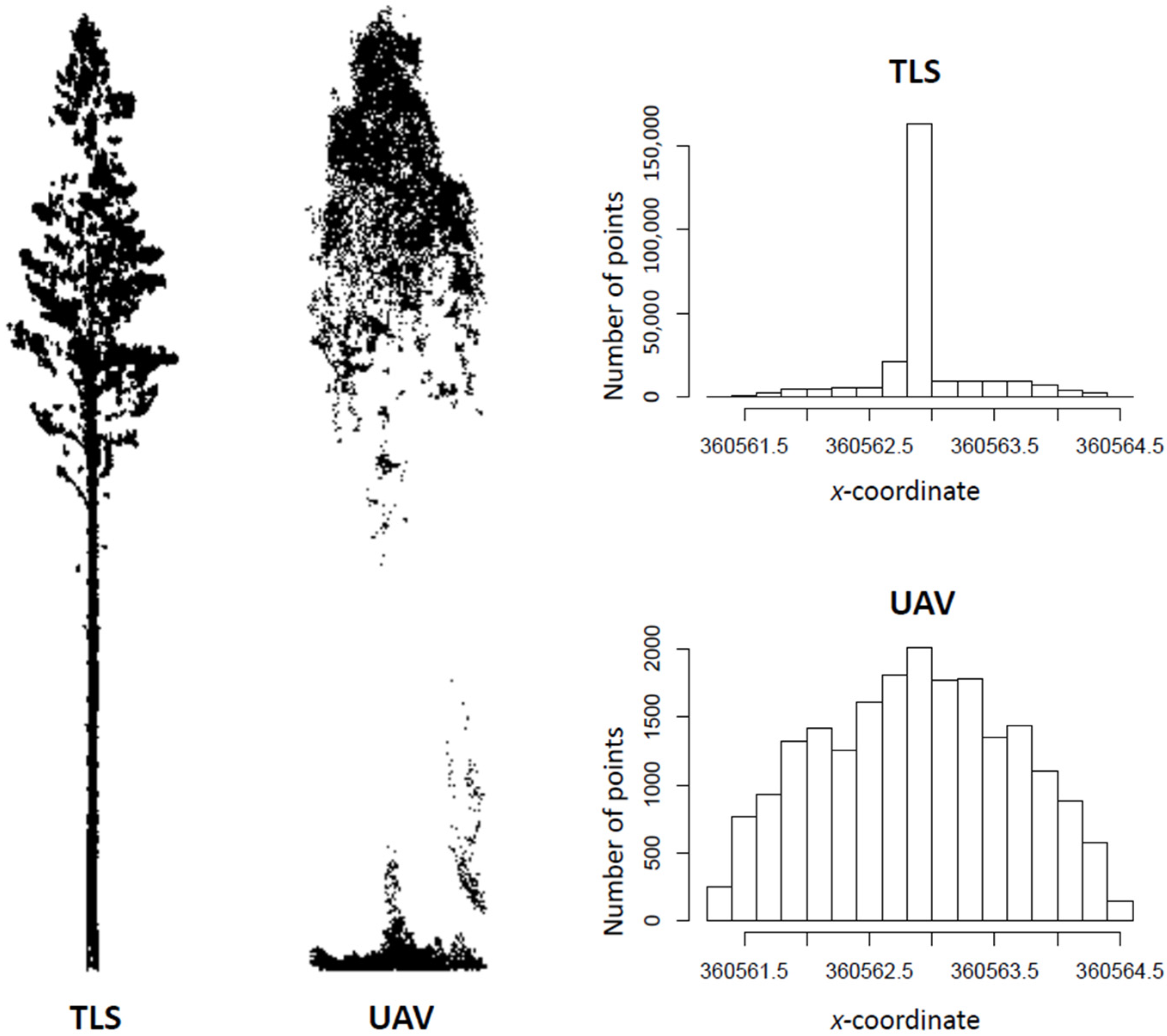
Compared to TLS measurements, the standard deviations of the points concerning all axes were larger in UAV measurements, but the ranges of point distances were smaller (Table 10). Figure 7 illustrates how TLS points are clustered in the center (i.e., in the stem), whereas UAV points are more evenly distributed.

Table 10.
On the left, the standard deviations of terrestrial laser scanning (TLS) and unmanned aerial vehicle (UAV) measured points with respect to all axes, and on the right, the difference between the ranges with standard deviations (UAV measured ranges subtracted from TLS measured).
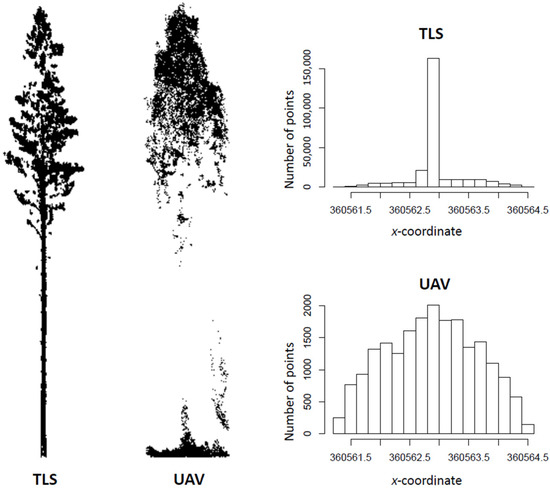
Figure 7.
Terrestrial laser scanning (TLS, left) and unmanned aerial vehicle (UAV, right) measured point clouds of an example, Scot’s pine tree. For this tree, TLS measured 260,000 points and UAV 20,000. The histograms (TLS top, UAV bottom) illustrate the number and distribution of the points with respect to the x-coordinate.
3.4. Tree Heights and Number of Boxes
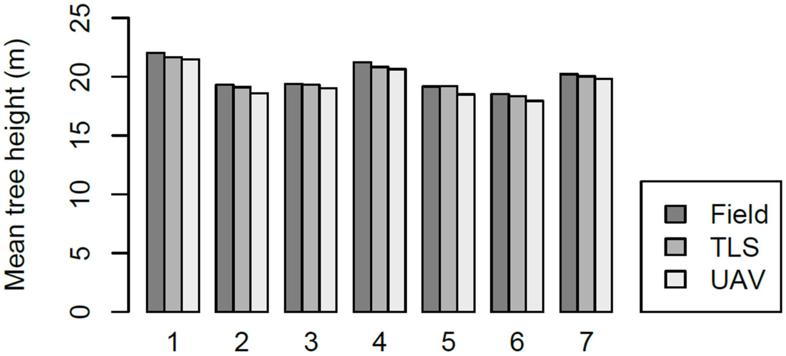
The mean differences between field measured tree heights, and TLS and UAV measured tree heights were 34 cm and 54 cm, respectively. Both TLS and UAV-derived tree heights were underestimates. Compared to field measurements, the RMSE of the point cloud-derived tree heights was 1.32 m for TLS and 1.44 m for UAV. RMSE was highest in the plots with no treatment and lowest in the intensive thinnings. The mean tree heights, mean differences, and RMSEs within different thinning treatments are presented in Figure 8 and Table 11.
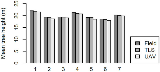
Figure 8.
Mean tree heights within different thinning treatments measured in the field and with terrestrial laser scanning (TLS) and unmanned aerial vehicle (UAV). Treatment numbers are explained in Table 2.

Table 11.
Mean tree heights (with standard deviations, ±) measured in the field and with terrestrial laser scanning (TLS) and unmanned aerial vehicle (UAV), and mean difference and root mean square error (RMSE) compared to the field measurements.
Since UAV underestimated the tree heights slightly more than TLS, the average number of required boxes was larger with all eight box sizes. Simple linear regression was used to determine whether the number of boxes affected TLS and UAV measured Db-values, and R2 for the three smallest box sizes varied between 76–80% with TLS and 64–68% with UAV (p-values < 0.001) (Table 12).

Table 12.
The average number of different box sizes required by terrestrial laser scanning (TLS) and unmanned aerial vehicle (UAV), h = tree height measured with either TLS or UAV, and h/n = tree height divided by n. The coefficient of determination (R2) explains how much the number of boxes affects the box dimension (Db) values; UAV > TLS shows how much more boxes UAV used than TLS.
4. Discussion
TLS and UAV measured Db-values of individual Scots pine trees differed significantly from each other. Four reasons were found for this: the differences in the number and distribution of the points, the estimated tree heights, and the number of boxes. Different thinning treatments significantly affected both TLS and UAV measured Db-values, but the forest structure had no significant effect on the divergence between TLS and UAV measured Db-values. Although TLS and UAV measured Db-values differed, their correlation was high.
4.1. Tree Detection
Db-values are relatively easy to calculate, but individual trees must first be detected and extracted from the point cloud data. In this study, TLS detected trees more efficiently than UAV, and the undetected trees were located mainly on the plots where no treatments or only moderate treatments had been performed, that is, on the plots with denser forest structures (Table 5). These results coincide with Liang et al. [19], who remarked that tree density is inversely proportional to the detection rates, and with Yrttimaa et al. [38]. They noted that tree and undergrowth density causes occlusion.
4.2. Box Dimension Values
The main result of this study was that TLS and UAV measured Db-values differed significantly, which answers research question 1. On average, UAV measured Db-values were 5% higher than TLS measured, and therefore UAV defined trees to be structurally more complex than was observed with TLS. The standard deviation and range of Db-values were larger with UAV than TLS, implying that the UAV measurements were not as consistent (Table 6). Although TLS and UAV measured Db-values differed, the correlation between them was 75%. This indicates that structurally complex trees were defined as complex by both methods, which confirms hypothesis 4.
The relationship between tree structural complexity and the forest structure has been examined in several studies, and the competitive pressure has been found to reduce Db-values [4,34,35,49]. The same observation was made in this study: stronger thinnings led to higher Db-values (Table 6). This is reasonable since, with intensive thinnings, there are less competition and more space to grow, which leads to the higher structural complexity of remaining trees.
As an answer to research question 3, the forest structure did not eliminate the divergence between TLS and UAV measurements, but with sparse forest structure, UAV obtained more points. The distribution of these points was more even than with dense forest structures (Table 7 and Table 9), which partly confirms hypothesis 3—the sparser the forest, the better UAV measurements correspond to TLS.
4.3. Number and Distribution of Points
Point density is one of the most important metrics for evaluating the quality of LiDAR equipment [50]. If the number of points per tree is limited, the structural complexity cannot be fully characterized [38]. As TLS measured 15 times more points than UAV (Table 7), it can be assumed that TLS described the structural complexity with a higher resolution and finer detail. However, the UAV measured Db-values with the highest amount of obtained points differed significantly from the TLS values (Table 8), implicating that the points’ distribution might be more important than the number of them.
Most TLS obtained points below the tree’s middle and vice versa with UAV. This is reasonable since TLS recorded tree characteristics below and UAV above the canopy. Regarding the point cloud density, the parameter settings used in the photogrammetric processing software while generating dense point clouds may influence the resulting point cloud properties and the respective complexity metrics derived from the point clouds.
The differences in standard deviations of points with respect to x- and y-axes (Table 10) can be explained by the measurement geometry and the fact that TLS was capable of characterizing the tree stem, whereas, with UAV, there were not that many observations of the stem and the points from the outer edges of the crown affected more to the point distribution. Furthermore, with UAV, more points were obtained from the upper part of the tree (Table 9). Still, at the same time, the ground vegetation was not properly excluded, which increased the standard deviation of the points on the z-axis. Therefore, the standard deviations of the points with respect to all axes were larger in UAV measurements. The ranges of UAV measured points, on the other hand, were smaller because UAV could not observe the extreme points and TLS and was averaging the treetops and sides. As in the Wilkinson et al. [51] study, UAVs rounded off the sharp edges of crowns. In addition, UAV-estimated tree heights were smaller than TLS-estimated, which affected the z-range.
4.4. Tree Heights and Number of Boxes
Typically, both TLS and UAV underestimate the tree heights [38,52]. Krooks et al. [53] reported a −2.2 m mean difference with 0.25 m standard error between TLS and the reference data in the stands, which were dominated by ~75-year-old Scots pine trees (600–800 stems/ha). In the study by Yrttimaa et al. [38], TLS underestimated the heights of Scots pine trees on average by 0.3 m with 1.6 m RMSE. Kameyama & Sugiura [52] examined the accuracy of UAV-SfM in the tree height measurements with Sakhalin fir trees (Abies sachalinensis) and noticed that the UAV-measured tree heights tended to be lower than the field measured. With the flight altitude of 140 m, the RMSE varied between 5.2 m (22%) and 7.2 m (35%) [52].
In this study, UAV underestimated tree heights more than TLS. Several studies have measured smaller tree heights with UAV photogrammetry than with TLS [54,55], but there are also opposite results [56]. Due to the occlusion caused by the terrestrial perspective, TLS could be expected to measure tree heights less well than UAV. Still, the sparse canopy of the pine forest and a multi-scan approach might have improved the situation.
From the box dimension perspective, the estimated tree height is important as it is used to choose the initial box size in Db-calculations. The more the tree height is underestimated, the smaller the initial box is, and the smaller the boxes, the more of them are needed to cover a tree. The more boxes, the higher the Db-value. In this study, UAV underestimated tree heights more than TLS, which led to more boxes (Table 11 and Table 12). The larger standard deviations of the UAV points further increased the number of boxes; accordingly, the observed structural complexity was higher with UAVs (Table 10 and Table 12). Due to the incapability of characterizing terrain through the forest canopy, the UAV point clouds were normalized using publicly available DTM at a resolution of 2 m × 2 m, which could affect the variation in the tree height estimation accuracy compared to TLS.
Based on the results of this study, hypotheses 1 and 2 can be confirmed. As an answer to research question 2, the differences in the number and distribution of the points in the TLS and UAV measured point clouds and the differences in the estimated tree heights and number of boxes explain the divergence between TLS and UAV measured Db-values.
4.5. Limitations and Future Work
The tree segmentation explains the differences in standard deviations and ranges of TLS and UAV acquired points. In this study, the plot-specific UAV point clouds were segmented so that all the points under each crown segment were included in the point cloud of an individual tree. Consequently, the individual trees included points from the ground vegetation (Figure 7). With TLS, the ground vegetation was excluded more efficiently. In contrast, UAV point clouds were more prone to inaccurate observations from near-ground vegetation due to their limited capacity to penetrate the forest canopy. The ground vegetation points in the UAV point clouds may thus have hampered the comparison between TLS and UAV measured Db-values. Further research should focus on methods to better eliminate the ground vegetation points.
Saarinen et al. [4] observed that the crown dimensions (i.e., crown width, projection, and volume) affected the structural complexity more than the stem attributes (i.e., DBH, height, and stem volume). In this study, TLS point clouds were divided into the canopy and stem points, but UAV point clouds were not, and the structural complexity of the canopies could not be compared. In future research, it would be noteworthy to investigate whether TLS and UAV measured Db-values of the canopies differ significantly from each other. This could also minimize the problem caused by UAV-measured ground vegetation points.
It should be noted that UAV data was originally acquired to supplement TLS measurements [28], and the sensor selection, imaging parameter selection, and data processing were performed specifically for this purpose. The results could have been closer to each other if the choices had been made from a different perspective. For example, by using lower flight altitude and larger oblique angles, it could be possible to obtain better penetration of the point clouds to capture more points from the ground level and inside the canopy. Camera technologies and point cloud extraction methods are also developing, thereby providing better image quality and greater resolution, which is assumed to impact the SfM-based point cloud quality.
In this study, UAV was equipped with digital cameras, but in recent research, also laser scanners have been used for this purpose (e.g., [57,58,59,60]). UAV laser scanning could have provided a more detailed vertical characterization of the trees and thus point clouds more comparable with TLS [61,62]. On the other hand, the measurement geometry of close-range terrestrial photogrammetry could have been better in line with that of TLS, resulting in more focus on the lower parts of the tree characteristics as with TLS [63,64]. Altogether, TLS represents the state-of-the-art geometric accuracy in point cloud characterization [65] and thus enables the comparison of other close-range sensing techniques such as UAV photogrammetry.
5. Conclusions
Since the structural complexity of trees supports various ecological processes and ecosystem services, complexity must be measured. Only with this knowledge can the structural complexity be fostered through forest management. A fractal-based box dimension method combined with point cloud data acquired with different remote sensing systems provides an objective and holistic measure of structural complexity. In this study, the structural complexity of individual Scots pine trees was assessed with box dimension values that were generated with point cloud data from TLS and aerial imagery acquired with a UAV. Photogrammetric point clouds collected above the canopy did not provide an identical characterization of the structural complexity compared to laser scanning point clouds collected under the canopy. The divergence between TLS and UAV measurements was found to be explained by the differences in the number and distribution of the points and the differences in the estimated tree heights and number of boxes in the box dimension method. Forest structure affected the variation of TLS and UAV measured Db-values, but the divergence between TLS and UAV remained significant. However, TLS and UAV measured box dimension values were highly correlated, and structurally complex trees were characterized as complex by both methods.
Author Contributions
Conceptualization, V.K., M.V. and N.S.; methodology, T.Y. and N.K.; software, T.Y.; validation, T.Y. and N.K.; formal analysis, N.T.; investigation, N.T. and N.S.; resources, E.H., S.H., J.H. (Jari Hynynen), M.H. and J.H. (Juha Hyyppä); data curation, T.Y., V.K., V.L., N.K. and N.S.; writing—original draft preparation, N.T.; writing—review and editing, N.T., T.Y., M.V., E.H., N.K. and N.S.; visualization, N.T.; supervision, N.S. and M.V.; project administration, N.S.; funding acquisition, M.V., E.H., M.H., J.H. (Juha Hyyppä) and N.S. All authors have read and agreed to the published version of the manuscript.
Funding
This study was funded by the Academy of Finland projects 315079, 345166, and 327861, the Centre of Excellence in Laser Scanning Research (project number 272195), and the Finnish Flagship Programme of the Academy of Finland (grant numbers 337127, 337655, 337656).
Conflicts of Interest
The authors declare no conflict of interest.
References
- Juchheim, J.; Ehbrecht, M.; Schall, P.; Ammer, C.; Seidel, D. Effect of Tree Species Mixing on Stand Structural Complexity. Forestry 2020, 93, 75–83. [Google Scholar] [CrossRef]
- Seidel, D.; Ehbrecht, M.; Dorji, Y.; Jambay, J.; Ammer, C.; Annighöfer, P. Identifying Architectural Characteristics That Determine Tree Structural Complexity. Trees Struct. Funct. 2019, 33, 911–919. [Google Scholar] [CrossRef]
- Saarinen, N.; Kankare, V.; Yrttimaa, T.; Viljanen, N.; Honkavaara, E.; Holopainen, M.; Hyyppä, J.; Huuskonen, S.; Hynynen, J.; Vastaranta, M. Assessing the Effects of Thinning on Stem Growth Allocation of Individual Scots Pine Trees. For. Ecol. Manag. 2020, 474, 118344. [Google Scholar] [CrossRef]
- Saarinen, N.; Calders, K.; Kankare, V.; Yrttimaa, T.; Junttila, S.; Luoma, V.; Huuskonen, S.; Hynynen, J.; Verbeeck, H. Understanding 3D Structural Complexity of Individual Scots Pine Trees with Different Management History. Ecol. Evol. 2021, 11, 2561–2572. [Google Scholar] [CrossRef] [PubMed]
- Seidel, D.; Annighöfer, P.; Ehbrecht, M.; Magdon, P.; Wöllauer, S.; Ammer, C. Deriving Stand Structural Complexity from Airborne Laser Scanning Data—What Does It Tell Us about a Forest? Remote Sens. 2020, 12, 1854. [Google Scholar] [CrossRef]
- Pommerening, A. Approaches to Quantifying Forest Structures. For. Int. J. For. Res. 2002, 75, 305–324. [Google Scholar] [CrossRef]
- Ribe, R.G. In-Stand Scenic Beauty of Variable Retention Harvests and Mature Forests in the U.S. Pacific Northwest: The Effects of Basal Area, Density, Retention Pattern and down Wood. J. Environ. Manag. 2009, 91, 245–260. [Google Scholar] [CrossRef]
- Ehbrecht, M.; Schall, P.; Ammer, C.; Seidel, D. Quantifying Stand Structural Complexity and Its Relationship with Forest Management, Tree Species Diversity and Microclimate. Agric. For. Meteorol. 2017, 242, 1–9. [Google Scholar] [CrossRef]
- Gough, C.M.; Atkins, J.W.; Fahey, R.T.; Hardiman, B.S. High Rates of Primary Production in Structurally Complex Forests. Ecology 2019, 100, e02864. [Google Scholar] [CrossRef]
- Hardiman, B.S.; Gough, C.M.; Halperin, A.; Hofmeister, K.L.; Nave, L.E.; Bohrer, G.; Curtis, P.S. Maintaining High Rates of Carbon Storage in Old Forests: A Mechanism Linking Canopy Structure to Forest Function. For. Ecol. Manag. 2013, 298, 111–119. [Google Scholar] [CrossRef]
- Jayathunga, S.; Owari, T.; Tsuyuki, S. Analysis of Forest Structural Complexity Using Airborne LiDAR Data and Aerial Photography in a Mixed Conifer–Broadleaf Forest in Northern Japan. J. For. Res. 2018, 29, 479–493. [Google Scholar] [CrossRef]
- Zenner, E.K.; Hibbs, D.E. A New Method for Modeling the Heterogeneity of Forest Structure. For. Ecol. Manag. 2000, 129, 75–87. [Google Scholar] [CrossRef]
- Füldner, K. Zur Strukturbeschreibung in Mischbeständen. Forstarchiv 1995, 66, 235–240. [Google Scholar]
- Seidel, D.; Ehbrecht, M.; Puettmann, K. Assessing Different Components of Three-Dimensional Forest Structure with Single-Scan Terrestrial Laser Scanning: A Case Study. For. Ecol. Manag. 2016, 381, 196–208. [Google Scholar] [CrossRef]
- Newnham, G.J.; Armston, J.D.; Calders, K.; Disney, M.I.; Lovell, J.L.; Schaaf, C.B.; Strahler, A.H.; Mark Danson, F. Terrestrial Laser Scanning for Plot-Scale Forest Measurement. Curr. For. Rep. 2015, 1, 239–251. [Google Scholar] [CrossRef]
- Brede, B.; Lau, A.; Bartholomeus, H.M.; Kooistra, L. Comparing RIEGL RiCOPTER UAV LiDAR Derived Canopy Height and DBH with Terrestrial LiDAR. Sensors 2017, 17, 2371. [Google Scholar] [CrossRef]
- Atkins, J.W.; Bohrer, G.; Fahey, R.T.; Hardiman, B.S.; Morin, T.H.; Stovall, A.E.L.; Zimmerman, N.; Gough, C.M. Quantifying Vegetation and Canopy Structural Complexity from Terrestrial LiDAR Data Using the Forestr r Package. Methods Ecol. Evol. 2018, 9, 2057–2066. [Google Scholar] [CrossRef]
- Reich, K.F.; Kunz, M.; von Oheimb, G. A New Index of Forest Structural Heterogeneity Using Tree Architectural Attributes Measured by Terrestrial Laser Scanning. Ecol. Indic. 2021, 133, 108412. [Google Scholar] [CrossRef]
- Liang, X.; Kankare, V.; Hyyppä, J.; Wang, Y.; Kukko, A.; Haggrén, H.; Yu, X.; Kaartinen, H.; Jaakkola, A.; Guan, F.; et al. Terrestrial Laser Scanning in Forest Inventories. ISPRS J. Photogramm. Remote Sens. 2016, 115, 63–77. [Google Scholar] [CrossRef]
- Westoby, M.J.; Brasington, J.; Glasser, N.F.; Hambrey, M.J.; Reynolds, J.M. ‘Structure-from-Motion’ Photogrammetry: A Low-Cost, Effective Tool for Geoscience Applications. Geomorphology 2012, 179, 300–314. [Google Scholar] [CrossRef]
- Johnson, K.; Nissen, E.; Saripalli, S.; Arrowsmith, J.R.; McGarey, P.; Scharer, K.; Williams, P.; Blisniuk, K. Rapid Mapping of Ultrafine Fault Zone Topography with Structure from Motion. Geosphere 2014, 10, 969–986. [Google Scholar] [CrossRef]
- Alexiou, S.; Deligiannakis, G.; Pallikarakis, A.; Papanikolaou, I.; Psomiadis, E.; Reicherter, K. Comparing High Accuracy T-LiDAR and UAV-SfM Derived Point Clouds for Geomorphological Change Detection. ISPRS Int. J. Geo-Inf. 2021, 10, 367. [Google Scholar] [CrossRef]
- Aicardi, I.; Dabove, P.; Lingua, A.M.; Piras, M. Integration between TLS and UAV Photogrammetry Techniques for Forestry Applications. Iforest Biogeosci. For. 2016, 10, 41. [Google Scholar] [CrossRef]
- Son, S.W.; Kim, D.W.; Sung, W.G.; Yu, J.J. Integrating UAV and TLS Approaches for Environmental Management: A Case Study of a Waste Stockpile Area. Remote Sens. 2020, 12, 1615. [Google Scholar] [CrossRef]
- Garcia, G.P.B.; Gomes, E.B.; Viana, C.D.; Grohmann, C.H. Comparing Terrestrial Laser Scanner and UAV-Based Photogrammetry to Generate a Landslide DEM. In Proceedings of the XIX Brazilian Symposium on Remote Sensing, Santos, Brazil, 14–17 April 2019; pp. 415–418. [Google Scholar]
- Wilkes, P.; Lau, A.; Disney, M.; Calders, K.; Burt, A.; Gonzalez de Tanago, J.; Bartholomeus, H.; Brede, B.; Herold, M. Data Acquisition Considerations for Terrestrial Laser Scanning of Forest Plots. Remote Sens. Environ. 2017, 196, 140–153. [Google Scholar] [CrossRef]
- van Leeuwen, M.; Nieuwenhuis, M. Retrieval of Forest Structural Parameters Using LiDAR Remote Sensing. Eur. J. For. Res. 2010, 129, 749–770. [Google Scholar] [CrossRef]
- Yrttimaa, T.; Saarinen, N.; Kankare, V.; Viljanen, N.; Hynynen, J.; Huuskonen, S.; Holopainen, M.; Hyyppä, J.; Honkavaara, E.; Vastaranta, M. Multisensorial Close-Range Sensing Generates Benefits for Characterization of Managed Scots Pine (Pinus sylvestris L.) Stands. ISPRS Int. J. Geo-Inf. 2020, 9, 309. [Google Scholar] [CrossRef]
- White, J.C.; Wulder, M.A.; Vastaranta, M.; Coops, N.C.; Pitt, D.; Woods, M. The Utility of Image-Based Point Clouds for Forest Inventory: A Comparison with Airborne Laser Scanning. Forests 2013, 4, 518–536. [Google Scholar] [CrossRef]
- Wallace, L.; Lucieer, A.; Malenovskỳ, Z.; Turner, D.; Vopěnka, P. Assessment of Forest Structure Using Two UAV Techniques: A Comparison of Airborne Laser Scanning and Structure from Motion (SfM) Point Clouds. Forests 2016, 7, 62. [Google Scholar] [CrossRef]
- Mandelbrot, B.B. The Fractal Geometry of Nature; W.H. Freeman Company: New York, NY, USA, 1977. [Google Scholar]
- Seidel, D. A Holistic Approach to Determine Tree Structural Complexity Based on Laser Scanning Data and Fractal Analysis. Ecol. Evol. 2018, 8, 128–134. [Google Scholar] [CrossRef]
- Feldman, D.P. Chaos and Fractals. An Elementary Introduction; Oxford University Press: Oxford, UK, 2012; ISBN 9780199566440. [Google Scholar]
- Dorji, Y.; Annighöfer, P.; Ammer, C.; Seidel, D. Response of Beech (Fagus sylvatica L.) Trees to Competition—New Insights from Using Fractal Analysis. Remote Sens. 2019, 11, 2656. [Google Scholar] [CrossRef]
- Seidel, D.; Annighöfer, P.; Stiers, M.; Zemp, C.D.; Burkardt, K.; Ehbrecht, M.; Willim, K.; Kreft, H.; Hölscher, D.; Ammer, C. How a Measure of Tree Structural Complexity Relates to Architectural Benefit-to-Cost Ratio, Light Availability, and Growth of Trees. Ecol. Evol. 2019, 9, 7134–7142. [Google Scholar] [CrossRef] [PubMed]
- Arseniou, G.; Macfarlane, D.W.; Seidel, D. Measuring the Contribution of Leaves to the Structural Complexity of Urban Tree Crowns with Terrestrial Laser Scanning. Remote Sens. 2021, 13, 2773. [Google Scholar] [CrossRef]
- Arseniou, G.; Macfarlane, D.W.; Seidel, D. Woody Surface Area Measurements with Terrestrial Laser Scanning Relate to the Anatomical and Structural Complexity of Urban Trees. Remote Sens. 2021, 13, 3153. [Google Scholar] [CrossRef]
- Yrttimaa, T.; Saarinen, N.; Kankare, V.; Hynynen, J.; Huuskonen, S.; Holopainen, M.; Hyyppä, J.; Vastaranta, M. Performance of Terrestrial Laser Scanning to Characterize Managed Scots Pine (Pinus sylvestris L.) Stands Is Dependent on Forest Structural Variation. ISPRS J. Photogramm. Remote Sens. 2020, 168, 277–287. [Google Scholar] [CrossRef]
- Finnish Forestry Practice and Management; Rantala, S. (Ed.) Metsäkustannus: Helsinki, Finland, 2011. [Google Scholar]
- James, M.R.; Robson, S. Mitigating Systematic Error in Topographic Models Derived from UAV and Ground-Based Image Networks. Earth Surf. Process. Landf. 2014, 39, 1413–1420. [Google Scholar] [CrossRef]
- Cunliffe, A.M.; Brazier, R.E.; Anderson, K. Ultra-Fine Grain Landscape-Scale Quantification of Dryland Vegetation Structure with Drone-Acquired Structure-from-Motion Photogrammetry. Remote Sens. Environ. 2016, 183, 129–143. [Google Scholar] [CrossRef]
- Viljanen, N.; Honkavaara, E.; Näsi, R.; Hakala, T.; Niemeläinen, O.; Kaivosoja, J. A Novel Machine Learning Method for Estimating Biomass of Grass Swards Using a Photogrammetric Canopy Height Model, Images and Vegetation Indices Captured by a Drone. Agriculture 2018, 8, 70. [Google Scholar] [CrossRef]
- Puliti, S.; Ørka, H.O.; Gobakken, T.; Næsset, E. Inventory of Small Forest Areas Using an Unmanned Aerial System. Remote Sens. 2015, 7, 9632–9654. [Google Scholar] [CrossRef]
- Isenburg, M. LAStools—Efficient LiDAR Processing Software (Version 181001 Academic) | Rapidlasso GmbH. Available online: https://rapidlasso.com/lastools/ (accessed on 18 July 2022).
- Ritter, T.; Schwarz, M.; Tockner, A.; Leisch, F.; Nothdurft, A. Automatic Mapping of Forest Stands Based on Three-Dimensional Point Clouds Derived from Terrestrial Laser-Scanning. Forests 2017, 8, 265. [Google Scholar] [CrossRef]
- Popescu, S.C.; Wynne, R.H. Seeing the Trees in the Forest: Using Lidar and Multispectral Data Fusion with Local Filtering and Variable Window Size for Estimating Tree Height. Photogramm. Eng. Remote Sens. 2004, 70, 589–604. [Google Scholar] [CrossRef]
- Meyer, F.; Beucher, S. Morphological Segmentation. J. Vis. Commun. Image Represent. 1990, 1, 21–46. [Google Scholar] [CrossRef]
- Plowright, A.; Roussel, J.-R. ForestTools: Analyzing Remotely Sensed Forest Data. R Package Version 0.2.5. Available online: https://cran.r-project.org/package=ForestTools (accessed on 11 August 2022).
- Juchheim, J.; Annighöfer, P.; Ammer, C.; Calders, K.; Raumonen, P.; Seidel, D. How Management Intensity and Neighborhood Composition Affect the Structure of Beech (Fagus sylvatica L.) Trees. Trees 2017, 31, 1723–1735. [Google Scholar] [CrossRef]
- Li, Q.; Ma, Y.; Anderson, J.; Curry, J.; Shan, J. Towards Uniform Point Density: Evaluation of an Adaptive Terrestrial Laser Scanner. Remote Sens. 2019, 11, 880. [Google Scholar] [CrossRef]
- Wilkinson, M.W.; Jones, R.R.; Woods, C.E.; Gilment, S.R.; McCaffrey, K.J.W.; Kokkalas, S.; Long, J.J. A Comparison of Terrestrial Laser Scanning and Structure-from-Motion Photogrammetry as Methods for Digital Outcrop Acquisition. Geosphere 2016, 12, 1865–1880. [Google Scholar] [CrossRef]
- Kameyama, S.; Sugiura, K. Estimating Tree Height and Volume Using Unmanned Aerial Vehicle Photography and SfM Technology, with Verification of Result Accuracy. Drones 2020, 4, 19. [Google Scholar] [CrossRef]
- Krooks, A.; Kaasalainen, S.; Kankare, V.; Joensuu, M.; Raumonen, P.; Kaasalainen, M. Predicting Tree Structure from Tree Height Using Terrestrial Laser Scanning and Quantitative Structure Models. Silva Fenn. 2014, 48, 1125. [Google Scholar] [CrossRef]
- Vaglio Laurin, G.; Ding, J.; Disney, M.; Bartholomeus, H.; Herold, M.; Papale, D.; Valentini, R. Tree Height in Tropical Forest as Measured by Different Ground, Proximal, and Remote Sensing Instruments, and Impacts on above Ground Biomass Estimates. Int. J. Appl. Earth Obs. Geoinf. 2019, 82, 101899. [Google Scholar] [CrossRef]
- Winczek, M.; Zięba-Kulawik, K.; Wężyk, P.; Strejczek-Jaźwińska, P.; Bobrowski, R.; Szparadowska, M.; Warchoł, A.; Kiedos, D. LiDAR and Image Point Clouds as a Source of 3D Information for a Smart City-the Case Study for Trees in Jordan Park in Kraków, Poland. In Proceedings of the Symposium GIS Ostrava 2020—UAV in Smart City and Smart Region, Ostrava, Czech Republic, 18–20 March 2020; Kačmařík, M., Růžička, J., Eds.; Available online: http://gisak.vsb.cz/GIS_Ostrava/GIS_Ova_2020/proceedings/papers/gis20205e3c1766d2e87.pdf (accessed on 11 August 2022).
- Roşca, S.; Suomalainen, J.; Bartholomeus, H.; Herold, M. Comparing Terrestrial Laser Scanning and Unmanned Aerial Vehicle Structure from Motion to Assess Top of Canopy Structure in Tropical Forests. Interface Focus 2018, 8, 20170038. [Google Scholar] [CrossRef]
- Brede, B.; Calders, K.; Lau, A.; Raumonen, P.; Bartholomeus, H.M.; Herold, M.; Kooistra, L. Non-Destructive Tree Volume Estimation through Quantitative Structure Modelling: Comparing UAV Laser Scanning with Terrestrial LIDAR. Remote Sens. Environ. 2019, 233, 111355. [Google Scholar] [CrossRef]
- Liang, X.; Wang, Y.; Pyörälä, J.; Lehtomäki, M.; Yu, X.; Kaartinen, H.; Kukko, A.; Honkavaara, E.; Issaoui, A.E.I.; Nevalainen, O.; et al. Forest in Situ Observations Using Unmanned Aerial Vehicle as an Alternative of Terrestrial Measurements. Ecosyst 2019, 6, 20. [Google Scholar] [CrossRef]
- Puliti, S.; Breidenbach, J.; Astrup, R. Estimation of Forest Growing Stock Volume with UAV Laser Scanning Data: Can It Be Done without Field Data? Remote Sens. 2020, 12, 1245. [Google Scholar] [CrossRef]
- Terryn, L.; Calders, K.; Bartholomeus, H.; Bartolo, R.E.; Brede, B.; D’hont, B.; Disney, M.; Herold, M.; Lau, A.; Shenkin, A.; et al. Quantifying Tropical Forest Structure through Terrestrial and UAV Laser Scanning Fusion in Australian Rainforests. Remote Sens. Environ. 2022, 271, 112912. [Google Scholar] [CrossRef]
- Jaakkola, A.; Hyyppä, J.; Kukko, A.; Yu, X.; Kaartinen, H.; Lehtomäki, M.; Lin, Y. A Low-Cost Multi-Sensoral Mobile Mapping System and Its Feasibility for Tree Measurements. ISPRS J. Photogramm. Remote Sens. 2010, 65, 514–522. [Google Scholar] [CrossRef]
- Jaakkola, A.; Hyyppä, J.; Yu, X.; Kukko, A.; Kaartinen, H.; Liang, X.; Hyyppä, H.; Wang, Y. Autonomous Collection of Forest Field Reference—The Outlook and a First Step with UAV Laser Scanning. Remote Sens. 2017, 9, 785. [Google Scholar] [CrossRef]
- Mokroš, M.; Liang, X.; Surový, P.; Valent, P.; Čerňava, J.; Chudý, F.; Tunák, D.; Saloň, I.; Merganič, J. Evaluation of Close-Range Photogrammetry Image Collection Methods for Estimating Tree Diameters. ISPRS Int. J. Geo-Inf. 2018, 7, 93. [Google Scholar] [CrossRef]
- Hunčaga, M.; Chudá, J.; Tomaštík, J.; Slámová, M.; Koreň, M.; Chudý, F. The Comparison of Stem Curve Accuracy Determined from Point Clouds Acquired by Different Terrestrial Remote Sensing Methods. Remote Sens. 2020, 12, 2739. [Google Scholar] [CrossRef]
- Morsdorf, F.; Kükenbrink, D.; Schneider, F.D.; Abegg, M.; Schaepman, M.E. Close-Range Laser Scanning in Forests: Towards Physically Based Semantics across Scales. Interface Focus 2018, 8, 20170046. [Google Scholar] [CrossRef]
Publisher’s Note: MDPI stays neutral with regard to jurisdictional claims in published maps and institutional affiliations. |
© 2022 by the authors. Licensee MDPI, Basel, Switzerland. This article is an open access article distributed under the terms and conditions of the Creative Commons Attribution (CC BY) license (https://creativecommons.org/licenses/by/4.0/).

