Article

Full Scale Evaluation of GFRP Confined Softwood after Long-Term Exposure to High Humidity Environment

1
Department of Civil Engineering, College of Engineering, Qassim University, Unaizah 56452, Saudi Arabia
2
Department of Civil Engineering, Monash University, Clayton, VIC 3800, Australia
3
Department of Civil and Environmental Engineering, The Hong Kong Polytechnic University, Hung Hom, Hong Kong 999077, China
4
Centre for Future Materials (CFM), School of Engineering, University of Southern Queensland, Toowoomba, QLD 4350, Australia
*
Author to whom correspondence should be addressed.
Forests 2023, 14(2), 343; https://doi.org/10.3390/f14020343
Submission received: 22 December 2022 / Revised: 1 February 2023 / Accepted: 7 February 2023 / Published: 9 February 2023

Abstract

:
Plantation softwood timber poles are associated with low natural durability, and it is also not clear what the effects of the high humidity environment on the long-term performance of composite action integrity of such a system. This paper presents a durability study for the proposed composite poles using (GFRP) glass fiber-reinforced polymer as a confinement system on wooden poles sourced from plantation softwood timber. Radiata pine poles of 6 m length were wrapped with multiple layers of 0°/90° woven roving biaxial E-glass fiber sheets through a wet layup process as confinement. The prepared GFRP softwood poles were then subjected to high humidity environmental conditions of up to 95 ± 2% relative humidity and 22 ± 2 °C temperature for a period of 30 months. Various lengths of confinement were considered in this study ranging from 0% to 70% of the span length. The poles had a span length of 5.4 m and were tested using a three-point bending test. Results showed that the proposed confinement system of GFRP-softwood provided a satisfactory long-term performance and the high humidity environment did not greatly affect the improvement in the mechanical performance that the GFRP system provided.

1. Introduction

Timber is commonly considered as a source of load bearing structural members in remote regions such as utility poles due to their desirable properties of cost-effective and nonconductive material and descended from renewable sources [1,2,3]. Moreover, a study was performed on assessing the life cycle of treated wooden utility poles with comparisons to steel and concrete utility poles, and it was found that the manufacture and installation of preservative-treated timber poles are less energy-intensive than those of either concrete or steel poles [4]. In Australia, according to a 2006 study report, around five million utility poles were made of timber and most of them were native hardwood, which were chosen due to their high durability in addition to their satisfactory mechanical properties [1]. This number represented about 80% of the total number of Australian utility poles. There is a need for about 75,000 new poles every year [5]; and moreover, about 70% of hardwood posts in service have been installed for many decades and require immediate replacement [1,2]. The reliability of utility poles is of utmost importance since power outages resulting from pole-failure can cause substantial financial losses and significant safety concerns [3,6].
Despite the desirable properties as mentioned, other concerns may occasionally call for the need of other pole types [7] and one disadvantage of timber is its vulnerability to biological deterioration over time (termite, fungus, or beetle attack), resulting in low durability in natural environments. A notable example, in South Australia and Northern Territory, timber poles are not in use due to the high termite hazard in those states. Alternatively, they mainly depend on Stobie and steel poles [1], where Stobie poles are basically made as a composite of two steel joists connected together by bolts, and the gap between them is filled with concrete. Another major issue of timber as a natural material is decay, which particularly causes external damage to timber poles, at the ground level that leads to a significant reduction in their load capacity. In a previous study [8], it was observed that decay of 25% of the external diameter of the timber pole would result in close to failure for the pole according to the strength criterion. This is because the outer 40% of the timber pole’s diameter accounts for 90% of its bending strength [1]. In order to help alleviate the decay problem faced by timber poles, and lengthen their lifespan, they require preservative treatment and constant maintenance [4]. However, the preservative treatments of timber require the use of toxic chemicals such as creosote and pentachlorophenol, which causes a negative impact on the environment and human health [9]. Towards the end of the last century, concerns regarding the use of toxic chemicals prompted the proscription of certain preservative chemicals [10].
Distribution timber utility poles in Australian remote regions are usually made of hardwood, which are harvested from the native forests. However, hardwood has become difficult and costly to obtain due to the hardwood shortage caused by deforestation and forest degradation. For example, by the 1980s, about 40% of forest in Australia had been altered by clearing [11]. In addition, large-scale hardwood forests were destroyed due to bushfires in 2002 and 2003 [2]. Environmental consciousness has further grown, which eventually led to agreements to reduce the logging of Australian native forests [1,5]. Therefore, there is an insistent demand to detect sources of another type of timber for utility poles. In Canada, the United States of America, and Europe, plantation-grown softwoods have been used and shown great benefit as distribution poles, which can be introduced as an alternative solution to the timber hardwood shortage, and they have recently been established in Victoria and Queensland [1]. However, studies confirmed that plantation softwoods are linked to low natural durability and consequently require additional treatments for preservation [1].
Fiber-reinforced polymer composites, as a confined material to poles made of softwood, particularly in the regions near ground-level, offer a promising solution to enhance the durability as well as the mechanical performance of softwoods [12]. In comparison to steel and concrete poles of higher cost and heavier weight associated with more effort in their transportation and installation [7], FRP provides considerable advantages such as resistance to corrosion, lightweight to high strength ratio, superior durability, and ease of installation [13,14,15,16,17,18,19,20,21,22,23,24,25,26,27,28,29,30,31,32,33,34,35]. The advantage of weight reduction in FRP may also quicken the installation operation and reduce transportation costs [36]. The use of glass fiber-reinforced polymer (GFRP) is considered an ideal option as reinforcing materials on the softwood pole surface due to their characteristic low electrical and thermal conductivity in addition to the low manufacture cost in comparison with other types of fiber-reinforced polymer materials, such as (CFRP) carbon fiber-reinforced polymer [37,38,39,40,41]. Despite the fact that structures made of GFRP materials are commonly affiliated with a higher initial cost in comparison to structures made of steel materials, a considerable advantage will be accomplished economically in the costs of maintenance over the duration of their service life [28,38].
Different studies showed that the use of composite materials made of FRP as a reinforcement system successfully improved the mechanical performance of timber in terms of strength and stiffness [3,27,42,43,44]. Most of these studies involved the rehabilitation of timber structures, and all of them indicated that FRP composites materials as confinement systems improved the mechanical performance of aged and decayed timber structures. Recently, a study [45] was conducted to investigate the mechanical performance of GFRP-confined softwood timber poles with different confinement lengths for application as utility poles using a wet layup method, where this practical method was widely used in the laboratory and workshop to fabricate small and thin FRP composite components or products [46]. The results obtained experimentally suggest that the use of multiple layers of E-glass fiber sheets of biaxial 0°/90° woven roving provided a significant increase in bending stiffness as well as the load-carrying capacity of the softwood poles [45]. The improvement in moment capacity was significant and reached 62% higher than the hardwood used in service [45]. It is worth mentioning that glass fiber has several grades, which are known by a letter nomenclature, such as E-glass, A-glass, C-glass, and S-glass. Where E-glass has high electrical resistivity, A-glass (window glass or alkali-resistant glass), C-glass has excellent corrosion-resistance, and S-glass (structural or high-strength glass) is used to produce the high-performance fibers used primarily in the aerospace industry. The properties of common grades of glass fibers are summarized in Table 1 [46].
Despite the fact that using GFRP composite materials as confinement systems for softwood poles provides an alternative solution to the hardwood shortage issue. It is important to highlight the role of bond behavior between the timber and FRP, as well as the effect of environmental conditions on the composite’s integrity. The stiffness and strength gained from the application of FRP to timber is dependent on the composite’s actions, i.e., it relies on the bond between the timber and FRP. Without proper bonding between the timber and the FRP, a partial composite action may occur [47], and that will lead to a notable reduction in the strength and stiffness of the structural member. Moreover, weak bonding can initiate the delamination process in an FRP-timber composite, and this may be worsened by environmental effects [48]. Therefore, the effects of the environmental conditions on the FRP-timber composite system need to be investigated. Furthermore, previous studies were performed on the effects of an aqueous environment on glass/epoxy composites, under both room temperature and 90 °C temperature, through submerging the GFRP specimens in water of controlled temperatures. For a temperature of less than 35 °C, the moisture level of FRP materials reached a saturation rate of 0.8%, and the mechanical properties of the composite were not significantly affected [49]. It may be concluded that the durability of the FRP coating itself may not be significantly affected by the humidity levels in the ground for such FRP-timber composite poles. However, since the FRP and timber act together through composite action, the durability of the FRP-timber composite system needs to be investigated further.
Therefore, the presented study in this paper will investigate the long-term performance of the proposed composite poles using (GFRP) glass fiber-reinforced polymer as a confinement system onto wooden poles sourced from plantation softwood timber after exposure to a high level of humidity. A process of wet layup system was used as a confinement method by using multiple E-glass fiber sheet layers of biaxial 0°/90° woven roving. Various lengths of confinement were prepared for the tested specimens and placed in an environment with a relative humidity of about 96% RH for 30 months. The exposed specimens were then examined in a three-point bending test, where strain gauges were installed at the midspan of the specimens and near the edge of the GFRP wrapping to recognize and explain the compressive and tensile strain behavior as well as to examine the degree of composite action of the GFRP-softwood sections. Experimental results, including failure modes, ultimate load, load-displacement responses, moisture content (MC), strain behavior, and bending stiffness, were obtained and thoroughly evaluated in this paper.
With regard to the recycling of composite materials, it is worth mentioning that GFRP-based products, in particular, are expected to have a long lifespan. Thus, the disposal of the proposed solution might not be a major concern in the next few decades. However, due to the growing production and consumption of using GFRP materials in the past few decades, the waste amount resulting from end-of-life GFRP products will definitely increase within the next few years, and this issue has become particularly worrying. Therefore, researchers have focused on developing recycling approaches for FRP composite materials, which might be very useful for this proposed solution [50,51].

2. Experimental Program

2.1. Materials

The selected timber poles in this investigation were unseasoned and untreated plantation softwood timber, which is called Radiata pine, widely available in Australia. The softwood poles had a diameter of 150 mm and moisture content (MC) of 40% and were wrapped with multiple layers of E-glass fiber fabric (biaxial plain weave 0°/90°), which were epoxy-impregnated sheets installed via wet layup. The epoxy used in the wet layup procedure consists of Epikure 3234 as a curing agent and Epon 828 as an epoxy resin. The GFRP confinement was composed of a total of 27 layers of 0°/90° woven roving as described in [45] where the fibers in a transverse direction enhance the hoop strength, in addition, to restraining the swelling of wood caused by water uptake [3], as well as improve the shear resistance [9,52]; while the fibers in the longitudinal direction produce the bending strength [3]. Each layer had a thickness of 0.26 mm and a weight of 400 gsm fabric. By knowing the fiber density, which is 2550 kg/m3 [53], and the total thickness of fully cured laminate, which is 8 mm, the volume fraction of fiber in the composites was calculated as 53%.
The GFRP properties can be obtained using (CLT) classical lamination theory [45,46] including the transverse and longitudinal in-plane modulus, the in-plane shear modulus, and the minor and major in-plane Poisson ratio, with the results presented in Table 2. The properties of softwood were obtained experimentally in accordance with the ASTM D143-94 standard [54], and the results are given in Table 2. The moisture content (MC) of the timber was measured after the GFRP-softwood pole specimens were subjected to high humidity condition, using the oven-dry method according to AS/NZS 1080.1 standard [55].

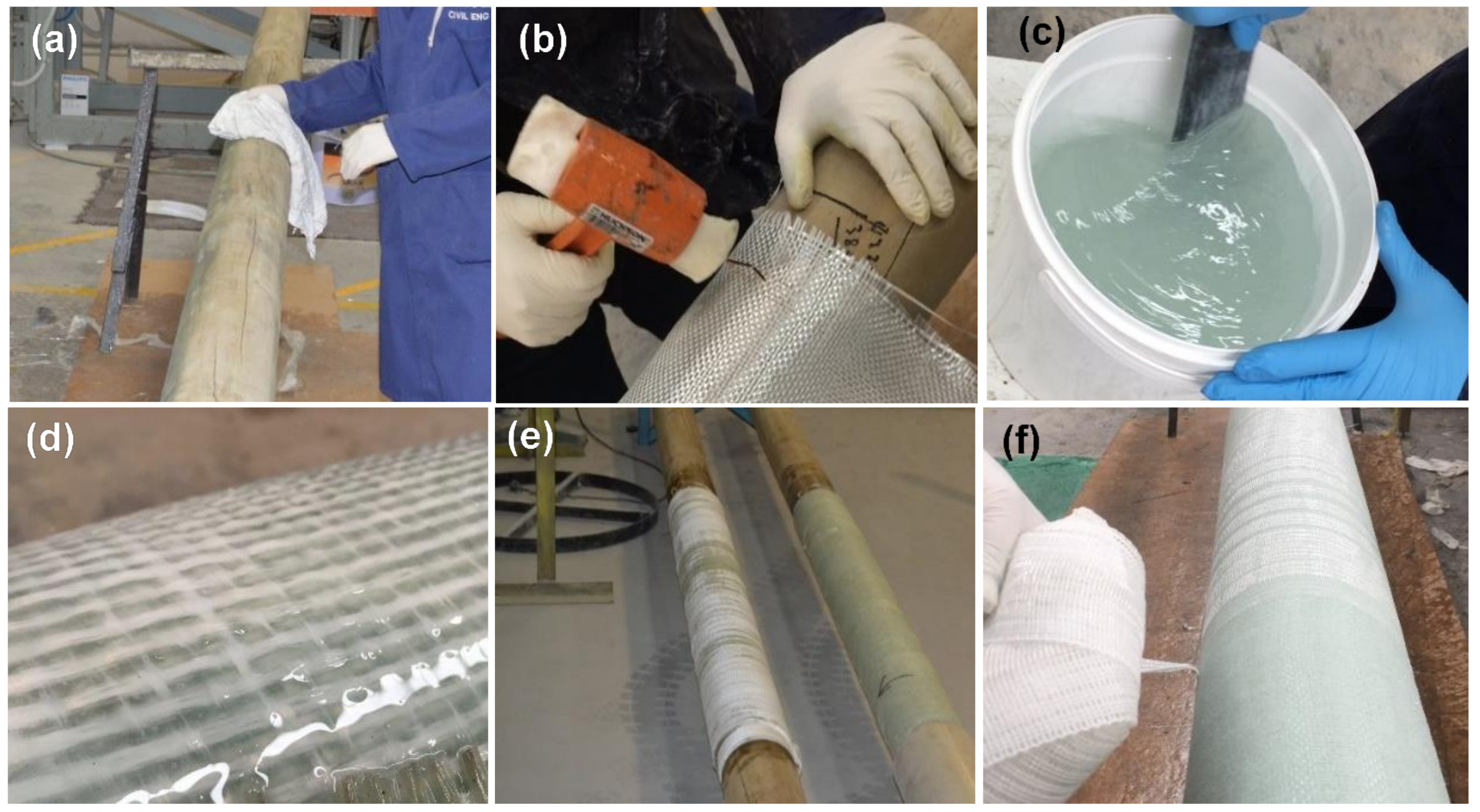
2.2. Specimens Preparation and Configurations

The fabrication process of GFRP along with the confinement procedure of GFRP timber pole specimens was carried out as presented in Figure 1a–f. The GFRP sheets were first attached onto the timber pole after proper surface cleaning [45]. The mixed epoxy was then impregnated on glass fiber sheets using a roller. After that, during the impregnating procedure, the timber softwood pole was carefully rolled in order to complete the whole layer, and after that, the operation is reduplicated for the remaining layers. The final stage of the GFRP confinement fabrication was to place the peel plies, where after the specimen was left to fully cure for about 24 h and then the peel ply was removed. The poles were allowed to fully cure for at least 14 days at a room temperature of 23 ± 2 °C and with 38 ± 2% relative humidity. Before the GFRP-timber poles were subjected to environmental conditions, preparations were further made at the two ends with a distance of 400 mm for the timber poles in order to protect the timber there as the supports in the three-point bending from local damage (natural deterioration due to high humidity) during the moisture exposure conditions (described ahead in Section 2.3), which might affect the testing performance where the main focus of this investigation is to examine the degree of composite action of GFRP-softwood sections. The preparation procedure for the support locations started with sanding the surface area. The surface was then coated with a paint product after cleaning the sanded area thoroughly. Finally, layers of plastic film were wrapped on top of the coated area and covered with thick heavy-duty plastic, which was then sealed by using heavy-duty duct tape.
The GFRP-softwood poles were exposed to the high humidity environment for 30 months and then tested for bending using a three-point setup to represent two symmetric cantilevers in order to simulate the true loading layout for utility pole applications. As shown in Figure 2, the tested specimens have a span length of 5.4 m and specimens were labelled TWEx, where x is the percentage of GFRP confinement from 0% to 70% of the span length. Each equivalent cantilever has a span length (L) of 2.675 m with a steel loading plate of 50 mm wide at the middle. The GFRP confinement length is Lw, where Le is the exposed length and Lt is the total length of GFRP confinement (see Figure 2). For example, in TWE70 with 70% GFRP confinement of the length of the span, Lw is calculated to be 1873 mm, while Le was 803 mm, and total confinement length Lt was 3795 mm, as shown in Table 3.

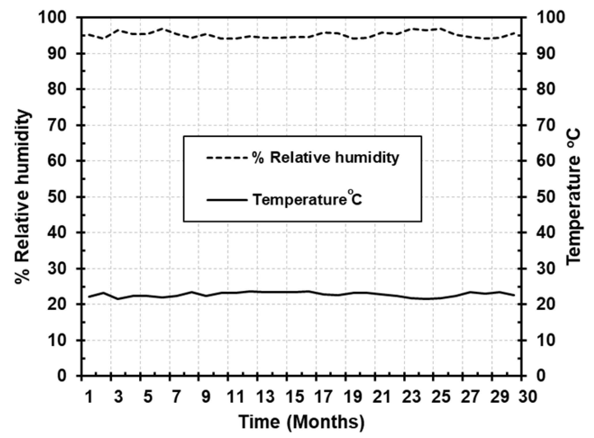
2.3. Moisture Exposure

The prepared GFRP-softwood pole specimens were placed into a room conditioned with 95 ± 2% relative humidity and a temperature of 22 ± 2 °C for period of 30 months. During the moisture exposure, the relative humidity and a temperature were measured once a week in order to maintain stable conditions as shown in Figure 3. An increase in the temperature of up to 40 °C may not affect the bonding between timber and FRP much [56] and therefore this study focusses on the effect of such a high humidity environment.
According to the climate statistics of Australia [57], the maximum measured relative humidity is around 80% in the Victoria region and this value is usually reached in one month every year. By subjecting the GFRP-softwood pole specimens to higher relative humidity conditions of about 95% for the period of 30 months, it would be assumed to represent 30 years of exposure of high humidity.

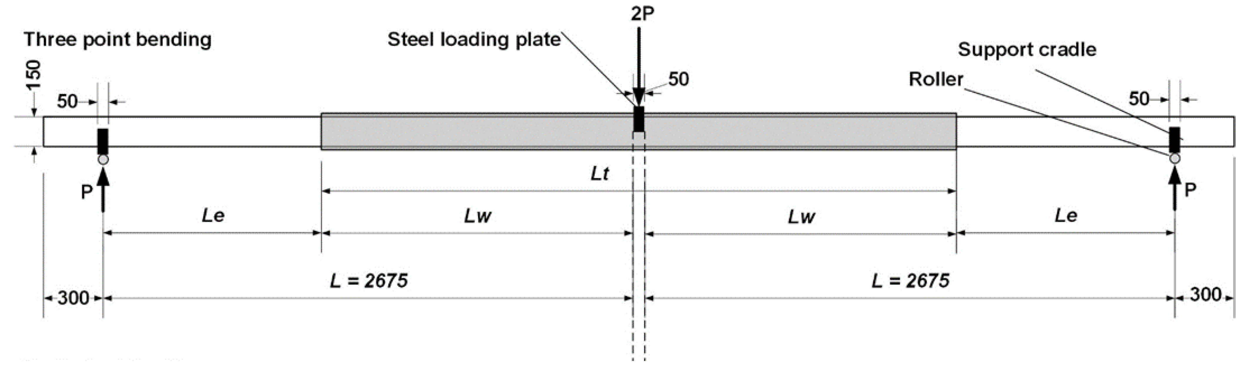
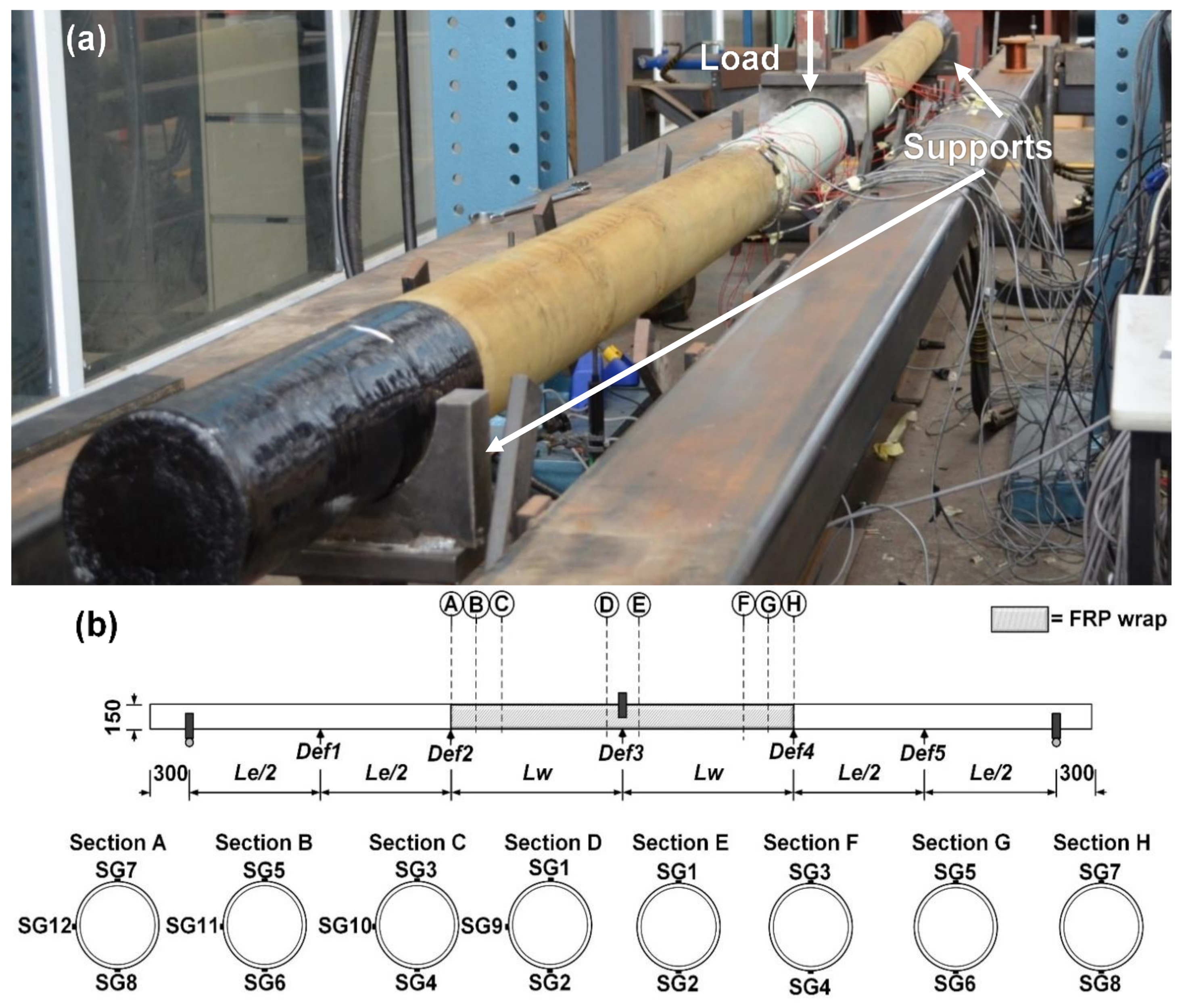
2.4. Mechanical Experimental Setup and Instrumentation

The experimental setup and instrumentation are illustrated in Figure 4. The specimens after environmental exposure were loaded into a three-point static bending setup and simply supported using an Instron 100 kN testing machine (see Figure 4a), where the test was performed at a room temperature of 23 ± 2 °C and with 38 ± 2% relative humidity. As shown in Figure 4b, strain gauges were positioned in the GFRP-softwood poles at the longitudinal direction of span along the bottom, top, and middle sides, using 120-ohm-resistant strain gauges. The strain gauges were attached to the critical locations in order to capture compressive and tensile strain responses as well as to evaluate the degree of the composite action (of the bonded sections GFRP/timber composite) after the high humidity exposure. As presented in Figure 4b, the strain gauges were attached to specimens TWE20, TWE30, and TWE70 and the locations of the strain gauges were divided into several regions along the span. As shown in Figure 4b, at the region of the midspan (section D), strain gauge SG1 was attached on the compression side and SG2 on the tension side while SG9 was in the mid-side of the specimens. The other regions, namely, section C, section B, and section A were located 200 mm, 100 mm, and 10 mm, respectively, from the edge of the GFRP wrapping, where strain gauges SG3, SG5, and SG7 were attached to the compression side while SG4, SG6, and SG8 were attached to the tension side, and SG10, SG11, and SG12 to the mid-side.
At the midspan, a 50 mm width loading steel cradle, a 250 mm length, and a 75 mm overall depth were applied to transfer the loads from the Instron actuator to the specimens. Two steel cradles with the same dimensions were used to support the specimens at two ends. The loading process was controlled at a rate of 6 mm/min using displacement mode. The displacements were measured using a string pot at the midspan and at the GFRP confinement ends. In addition, two linear potentiometers (LVDT) were placed at the middle of the exposed timber regions to understand displacement responses and deformed shapes of specimens.

3. Experimental Results and Discussion

3.1. Failure Modes

As presented in Figure 5, one dominant failure mode was observed from the tested timber pole specimens, which was a timber tensile failure. All the specimens that have 0% to 70% range of GFRP confinement span length (i.e., TWE0 to TWE70) exhibited a sudden flexural tensile failure of the timber pole at their ultimate loads. For the timber pole specimens with confined GFRP, no damages were observed on the GFRP during the loading process. The failure happened at the midspan as seen in Figure 5a for TWE0 without GFRP confinement and there were sounds of cracking when approaching the ultimate load. For TWE20, TWE30, and TWE70, the failures occurred on the timber at one side of the GFRP wrapping edge at the ultimate loads (see Figure 5b–d). It is important to mention that the timber tensile failure for specimens with GFRP wrapping was initiated from inside the GFRP wrapping. Therefore, it is believed that such behavior may be caused by the degradation of the adhesive bond between timber and GFRP, leading to a loss of composite action between GFRP and timber after the exposure to a high level of relative humidity for 30 months (further discussion in Section 3.3). For the timber pole specimens with confined GFRP ranging from 20% to 70% of the span length, the damaged specimens were removed immediately after each test in order to measure the depth of timber failure inside the GFRP wrapping. It was found that for TWE20, TWE30, and TWE70 the depths of timber failure inside the GFRP wrapping were 11 mm, 17 mm, and 58 mm, respectively.
In a recent experimental investigation performed on timber poles made of GFRP and softwood with the same configurations but without environmental exposure [45], it was concluded that there were only two major observations in terms of failure modes there. First, timber tensile failure for the timber pole specimens with confined GFRP ranging from 0% to 30% of the span length (i.e., TW0 to TW30), identical to TWE0, TWE20, TWE30, and TWE70. However, without environmental exposure, the specimens in [46] showed a good bonding quality, which was evidenced by the timber failure located at 100–250 mm outside the confined GFRP. In [45], the second failure mode was GFRP fracture located in the midspan in both tension and compression sides for the TW70 specimen, and this failure mode was not observed in the current study for specimen TWE70.

3.2. Load–Displacement Behavior

Figure 6 shows a comparison of the load (or midspan moment)–deflection responses up to the failure for the TWE specimens that were exposed to high humidity and the TW specimens without environmental exposure in [45], the numbers beside the labels represent the percentage of confined GFRP (ranging from 0% to 70%).
Overall, TW specimens without environmental exposure showed load (or midspan moment)-deflection responses linearly up to their ultimate load capacities. In contrast, the TWE specimens that were exposed to high humidity exhibited a linear response in terms of load-deflection up to around 50%–52% Pu (ultimate load) for TWE0, TWE20, and TWE30, or 69% Pu (ultimate load) for TWE70. As these nonlinear responses were noticed, it is believed that such behavior in the TWE specimens can be caused by the high moisture content of the timber poles after exposure to high humidity for a long period of time. For the TWE0 specimen with no confined GFRP, the ultimate capacity of the load was 6.5 kN, which corresponded to the maximum capacity of the moment of 8.8 kN·m at the midspan, where a sudden flexural tensile failure occurred in the timber. After the experiment was completed, timber samples were immediately taken from TWE0 in order to measure the moisture content using the oven-dry method according to the AS/NZS 1080.1 standard [55], and the result was 83.9%.
For TWE20 or TWE30, the ultimate capacity of the load Pu was 5.9 kN or 10.3 kN, respectively. However, as shown in Figure 5b,c, the failure scenarios for both specimens did not occur in the middle span, only on the timber pole portion close to the rim of confined GFRP. At the midspan for TWE20, the maximum capacity of the moment was 8 kN·m with moisture content of 78.1% and for TWE30 was 13.9 kN.m with moisture content of 64.3%. The TWE70 specimen exhibited a considerable increase in the capacity of the load, and the ultimate capacity of the load was 28.5 kN, which corresponded with the maximum capacity of the moment of 38.4 kN·m. The specimen failed similar to specimens TWE20 and TWE30 when a sudden timber tensile failure of the pole occurred close to the rim of confined GFRP. The moisture content (MC) for TWE70 was measured as 56.4%.
It can be identified from Figure 6 that the ultimate load capacity and therefore the maximum moment capacity for the TWE specimens were close to the TW specimens without environmental exposure, with a maximum difference of 18.3% (also see Table 4). This is because the timber poles for the unexposed TW specimens were unseasoned and their moisture contents were around 40%. This value is greater than the fiber saturation point of Radiata pine species of around 30% [58,59]. Consequently, the ultimate load capacity was not significantly affected by the high humidity exposure as the mechanical properties (strength in particular) of the timber would not change much for moisture content beyond the fiber saturation point [60,61,62].
Five displacement transducers were placed as shown in Figure 4b and therefore the deformed shapes received in Figure 7 for the specimens of TWE at the load of 3.5 kN in comparison to those from TW specimens without humidity exposure. For both exposed and unexposed GFRP-softwood pole specimens, the overall deformations were substantially decreased when the GFRP confinement length increased. Furthermore, the differences in displacement at the load of 3.5 kN were also remarkably reduced as the GFRP confinement length increases of equivalent confinement length between TW and TWE specimens.

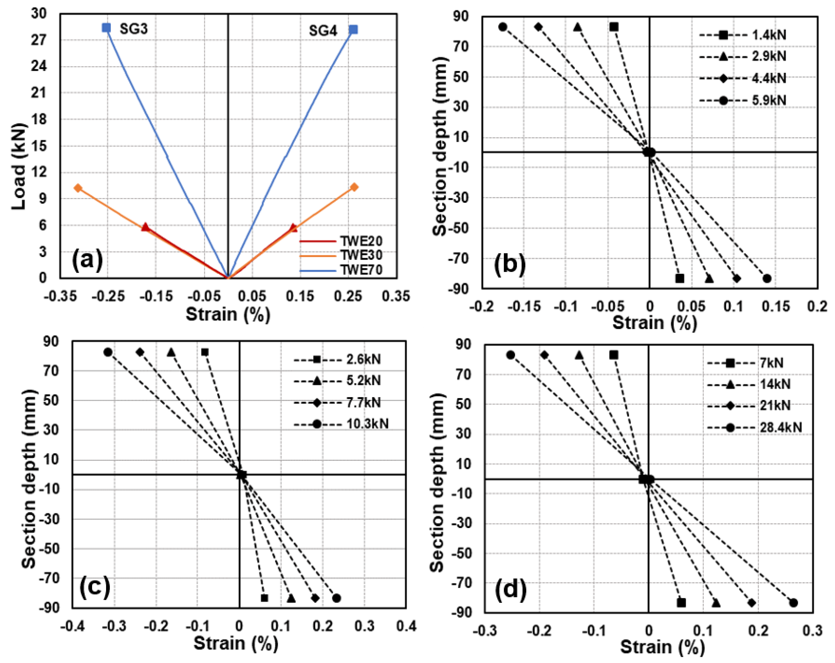
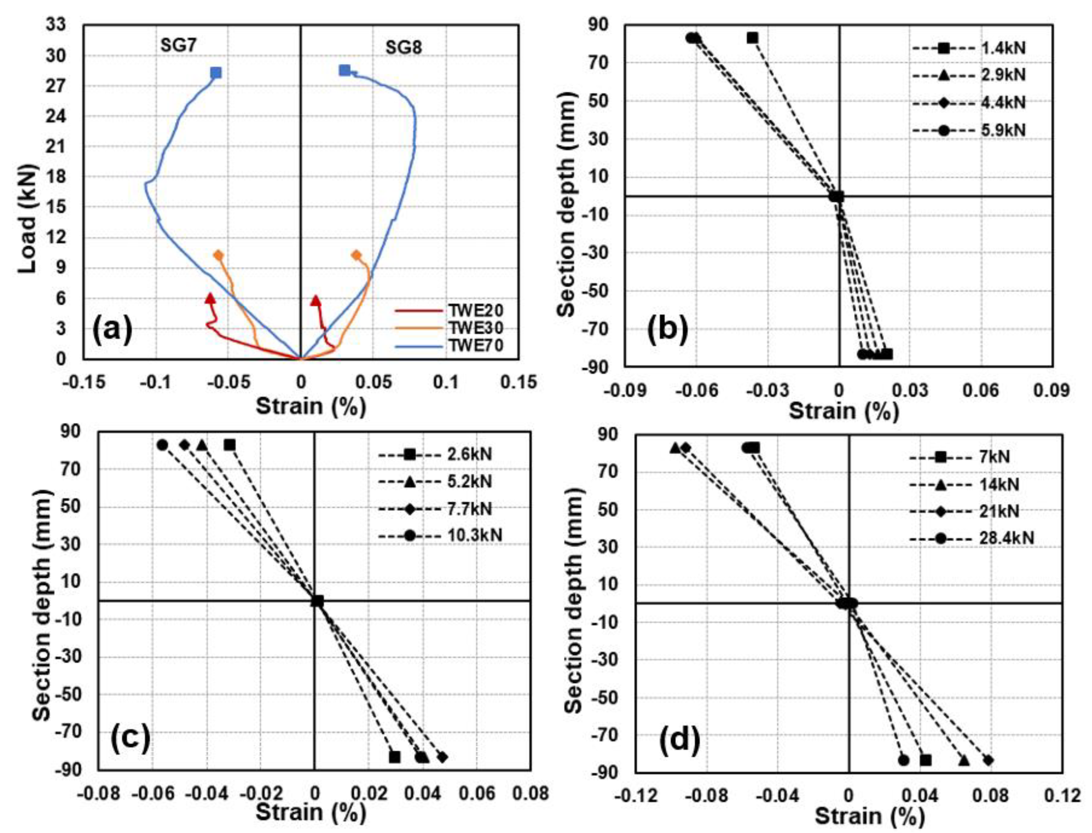
3.3. Load–Strain Behavior and Composite Action

Figure 8a shows the load axial strain curves for the TWE specimens TWE20, TWE30, and TWE70 at the midspan in comparison with the TW specimens without environmental exposure. Due to similarity, the strain values and curves were presented for only one-half of the symmetry of each specimen. Overall, the load–strain curves for the TWE specimens showed linear behavior up to the ultimate loads similar to the TW specimens, indicating that satisfactory bonding was maintained at the midspan section during the loading process. A slight nonlinearity was noticed for specimens with 70% confinement length, where those particular specimens experienced much larger deformations compared to the others, where such behavior (slight nonlinearity) might happen. Moreover, Figure 8b–d shows the strain distributions at section D along the section depth for TWE20, TWE30, and TWE70 specimens at different load levels. The axial strain distribution along the section depth was linear, which indicates that a full composite action between the bonded materials (timber and GFRP) was achieved at the midspan (section D). It is noteworthy that, at the midspan where the maximum strain values were expected, all TWE specimens showed maximum strain values significantly lower than the typical maximum compressive and tensile strains value of the GFRP materials [63,64], indicating no damages to the GFRP wrapping during the experiments. Figure 9a shows that the load axial strain curves from section C for the specimens TWE20, TWE30, and TWE70 are located 200 mm from the edge of GFRP wrapping (see Figure 4b). All the TWE specimens exhibited linear strain behavior (from SG3 and SG4) up to their ultimate loads, similar to those in the midspan strain responses. Furthermore, Figure 9b–d shows linear axial strain distribution along the section depth for the TWE specimens and these results demonstrated that the full composite action was still maintained there for section C.
As shown in Figure 10a, TWE30 and TWE70 at section B with a distance of 100 mm (see Figure 4b) showed approximately linear (slight nonlinearity is believed to be due to the high MC of timber when approaching the beginning of GFRP wrapping) load axial strain curves with close strain values from SG5 and SG6; and this indicated that good bonding quality was likely still maintained for the specimens with 30% and 70% of confined GFRP of the span length. Even though the load axial strain curve was approximately linear, Figure 10a for TWE20, its SG6 in the tension side showed remarkably lower strain magnitude at different load levels as compared to SG5 in compression as seen in Figure 10b. This can be considered a sign of debonding that initiated during the loading process on the tension side, suggesting that the adhesive bond between timber and GFRP around section B for the TWE20 specimen was affected by the high humidity environment. Figure 10c,d demonstrates linear axial strain distribution along the section depth for TWE30 and TWE70 specimens indicating that the full composite action was still preserved there at section B.
Strain gauges SG7 (compression) and SG8 (tension) were attached at section A, 10 mm away from the beginning of GFRP wrapping for specimens TWE20, TWE30, and TWE70. As evidenced by Figure 11a–d, irregular changes in the strain developments with load are found from SG7 and SG8 for all the tested TWE specimens, such as the nonlinear behavior and the discrepancy in the strains measured from SG7 and SG8 at the ultimate load. This suggests that the bond interface between the GFRP wrapping and timber may be severely affected by the high humidity environment and therefore there was an obvious degradation in GFRP-timber composite action in section A.
The affected sections from the environmental exposure can be identified for the tested TWE specimens based on the above discussions about strain results. Therefore, the derived degradation in bonding between GFRP and timber is quantified in Table 4, as a percentage in reference to the total confinement length for each specimen. For example, for TWE20, section A (10 mm from edge of GFRP) and section B (100 mm from edge of GFRP) indicated potential debonding while the first sign of full composite action between GFRP and timber was seen in section C (200 mm from edge of GFRP). This suggests that potential debonding may be within a total of no more than 400 mm from the GFRP confinement length, corresponding to the maximum degradation in bonding of 35.7%. It is worth mentioning that the GFRP wrapping withstood and restrained the swelling of wood throughout the exposure, where the circumferences of the GFRP-softwood sections were measured for the tested specimens before and after the humidity exposure, and the results were identical.

3.4. Bending Stiffness

The bending stiffness (EIexp) of the specimens (TWE TWE0, TWE20, TWE30, and TWE70) can be determined using beam theory [65]. Due to the large span length of the GFRP-timber composite specimens and the governing flexural deformation, shear deformation was not considered. Thus, the bending stiffness can be calculated from Equation (1)
E I e x p = L 3 48   P δ
where L is the span length of the tested pole under three-point static bending, the value of P is the load applied at midspan, and δ is the deflection at midspan, which were obtained from the linear elastic stage of the load–displacement curve of the experimental results, which are presented in Figure 6.
In general, reductions in the bending stiffness can be noticed for the TWE specimens that were subjected to a high humidity condition in comparison to the specimens without environmental exposure. As shown in Table 4, for specimen TWE0 without GFRP wrapping, the bending stiffness was only decreased by 6.1% compared to the unexposed specimen. Specimen TWE20 showed more reduction in bending stiffness of 16.4% in comparison to specimen TW20 without environmental exposure. The cause of such reduction in bending stiffness for TWE20 is believed to be the degradation in the bonding and the induced partial composite action as discussed previously. With 30% wrapping (TWE30), the bending stiffness was decreased by 11.7% compared to the unexposed TW30 specimen. Slight reduction was seen for TWE70 in the bending stiffness of 3.4% as compared to the specimen without environmental exposure.
The tensile and compressive stresses of the GFRP-timber composite section at midspan can be determined from Equation (2), for the TWE specimens
σ = E F R P   ϵ
where σ is the stress at the outward fiber of the midspan composite section in the GFRP confinement that occurs when timber fails at the section near to the edge of the GFRP wrapping material, the GFRP elastic modulus is EFRP (23.2 GPa, see Section 2.1), and ϵ is the obtained strain value from experimental results in the outward fiber at the ultimate load Pu (see Table 4). All the tested TWE specimens showed significantly lower values for their maximum stresses in comparison to the typical maximum compressive and tensile strengths of the GFRP materials, supporting that the failure at their midspan regions did not happen on GFRP.

4. Moment Capacity Comparisons

In order to consider the proposed GFRP-softwood composite poles as an alternative solution to hardwood, the moment capacity results obtained from the specimens that were exposed to a high humidity must be compared to existing hardwood applications. Corymbia (spotted gum) and Eucalyptus pilularis (blackbutt) are the most widespread hardwood species currently in use as poles throughout Australia [1]. According to AS/NZS 2878, these are hardwood pole species classified into strength group S2 [66].
The timber poles in Australia are classified into seven strength groups ranging from a maximum bending characteristic strength of 100 MPa (strength group S1) to the minimum bending characteristic strength of 25 MPa (strength group S7) and the moment capacity of poles in bending (Mb) can be determined by using Equation (3) [67].
M b = f b Z
where Mb is the pole capacity at the moment, f b is the characteristic bending strength (S1 to S7), and Z is the section modulus, i.e., π d p 3 32 , where dp is the diameter of the pole. The specimens used in this study were softwood and had 150 mm diameters where dp in the above equation is assumed.
The experimental moment capacities for the GFRP softwood pole specimens that were subjected to a high humidity environment are given (see Section 3.2). The specimen TWE0 without GFRP wrapping has a moment capacity of 8.8 kN·m, which could be categorized between strength groups S6 and S7. TWE20 with a moment capacity of 8 kN·m is very close to strength group S7. The moment capacity Mb for TWE30 is 13.9 kN·m, which can be classified between strength groups S4 and S5. The specimen TWE70 has a higher moment capacity of 38.4 kN·m, which corresponds to 16.1% and this value is greater than the highest strength group S1. Spotted gum and blackbutt, currently in use as hardwood pole species, have moment capacities of 26.5 kN·m for poles of 150 mm in diameter, and are categorized into strength group S2. This suggests that 70% of the confinement length of the proposed GFRP enhancement method for softwood can reach 45% higher than the hardwood poles in use such as Corymbia (spotted gum) as well as Eucalyptus pilularis (blackbutt).

5. Recommendations

The results obtained from this study have confirmed that the GFRP-softwood confinement system provided a moment capacity 45% higher than the hardwood pole species in use when pushed further under extreme weather conditions such as high humidity environment for 30 months. These results represent the specimen with 70% of the confinement length of the Radiata pine softwood. Further investigations may be expected to identify the optimal confinement length for softwood that would satisfy design requirements, as existing hardwood utility poles are currently in service. Moreover, the softwood used in this investigation was unseasoned Radiata pine (Pinus radiata) with relatively lower mechanical properties (such as strength and modulus of elasticity) as compared to the seasoned timber from the same species. The selection of seasoned softwood may provide larger improvement in the GFRP-softwood confinement system, and therefore a lower GFRP confinement length may satisfy the design requirements. It is worth mentioning that the base of the proposed GFRP-softwood must be sealed entirely, either with an epoxy coating or a few layers of GFRP, in order to avoid any fungus that causes decay from ground-level. Thus, field durability tests should be performed using the accelerating aging approach in future work in order to obtain a better design method to cover the base of the proposed GFRP-softwood pole. For the regions or states where high termite hazards exist, it is beneficial to apply GFRP confinement onto the remaining surfaces of the timber pole for protection against any biological deterioration in order to avoid using the traditional preservative solutions of timber poles with hazardous waste due to chromium and arsenic. Finally, a comprehensive economic analysis can be performed to estimate the total cost reductions for the proposed solution throughout the expected lifespan of the GFRP-softwood poles in future works, as compared with other solutions.

6. Conclusions

Mechanical performance of the composite timber poles made of GFRP and softwood after long-term exposure to a high humidity environment was investigated in this study. The effects of 95 ± 2% high relative humidity along with the difference in confinement length on the flexural performance of the proposed composite timber pole (GFRP-softwood) specimens were clarified. The ultimate load, load-displacement responses, moisture content, failure modes, bending stiffness, and strain behavior were experimentally obtained and evaluated. From these investigations, the following conclusions can be drawn:
(1)
The ultimate load capacities for specimens with 0% to 70% GFRP confinement of the span length (i.e., TWE0 to TWE70) after exposure to high humidity environment for 30 months were found to be close to the specimens without environmental exposure and the maximum difference in the ultimate load capacity was about 18% for the specimen that has 20% GFRP confinement length of the span (i.e., TWE20).
(2)
All the specimens with GFRP confinement after environmental exposure showed a similar failure mode as a sudden flexural tensile failure of timber at the ultimate loads. For the TWE0 specimen without GFRP wrapping the failure happened on the midspan, while the specimens with 20% to 70% GFRP wrapping, failed on the timber at one portion close to the rim of the GFRP confinement. However, the depths of timber failure inside the GFRP wrapping were different, namely, 11 mm, 17 mm, and 58 mm for specimens with 20%, 30%, and 70% GFRP wrapping, respectively.
(3)
GFRP-softwood composite specimens showed different performances, in terms of the moisture content after exposure and subsequent load-displacement responses, with the GFRP confinement length. The load-deflection responses started to change from linear to nonlinear when ultimate loads of about 50% were reached for the specimens with 20% and 30% GFRP confinement. The nonlinear response started for the TWE70 specimen ultimate load of at about 70%. The moisture content for the specimens decreased when the GFRP confinement length increased.
(4)
After exposure to high humidity for 30 months, full composite action between the GFRP and softwood was maintained for most of the bonded area in the softwood and GFRP composite specimens. For specimen TWE20 with 20% GFRP confinement, the first sign of debonding was 100 mm away from the rim of the GFRP confinement and the degradation in bonding was estimated to be 35.7% of the confinement length based on the strain responses at various sections along the span. For the specimens with 30% and 70% GFRP confinement span length, the degradation in bonding was estimated to be 12.1% and 5.7% of the overall confinement length, respectively.
(5)
The high humidity exposure of 30 months causes a reduction in bending stiffness for all the specimens. For the specimen without GFRP wrapping the bending stiffness decreased slightly by 6.1% compared to the unexposed one. The role of degradation in composite action caused more reduction in bending stiffness of 16.4% for specimen TWE20 with 20% confinement, and of 11.7% for the specimen with 30% GFRP confinement. For specimen TWE70 with 70% GFRP confinement, the environmental effect was minor with only 3.3% reduction in bending stiffness.
(6)
The capacity of the moment from the experimental results of the GFRP-softwood composite system after 30 months of exposure can be classified into several strength groups in accordance with the relevant standard (AS/NZS 2878. Timber-classification into strength groups, Standards Australia). Where specimens with 0% and 20% confinement with moment capacities of 8.8 kN·m and 8 kN·m correspond to the lowest strength groups—S6 and S7. Specimen TWE30 with 30% confinement presents the capacity of the moment of 13.4 kN·m and is located between strength groups S5 and S4. TWE70 showed 16.1% higher moment capacity compared to the highest strength group, S1, and it is also 45% higher than the hardwood pole species such as Corymbia (spotted gum) and Eucalyptus pilularis (blackbutt) currently in use.
This study may propose an alternative solution using GFRP as a confinement system for existing softwood to improve its mechanical properties and durability performance, considering the shortage of traditional hardwood poles. Equally important, GFRP materials have excellent resistance to corrosion and biodeterioration as well as being an environmentally friendly solution compared to the traditional preservative solutions of timber poles with hazardous waste due to chromium and arsenic.

Author Contributions

Conceptualization, A.D.A. and Y.B.; methodology, A.D.A. and Y.B.; software, A.D.A.; validation, A.D.A. and W.F.; formal analysis, A.D.A.; investigation, A.D.A.; resources Y.B.; data curation, A.D.A.; writing—original draft preparation, A.D.A.; writing—review and editing, A.D.A., Y.B., X.-L.Z. and W.F.; visualization, A.D.A. and Y.B.; supervision, Y.B., X.-L.Z. and W.F. All authors have read and agreed to the published version of the manuscript.

Funding

This research was funded by the Australian Research Council (ARC) Linkage project (LP180102208).

Institutional Review Board Statement

Not applicable.

Informed Consent Statement

Not applicable.

Data Availability Statement

The raw/processed data required to reproduce these findings cannot be shared at this time as the data also form part of an ongoing study.

Acknowledgments

The authors acknowledge the support from the Australian Research Council (ARC) Linkage project (LP180102208) and the authors would like to thank the Deanship of Scientific Research, Qassim University, for funding the publication of this project; and also wish to acknowledge Long Goh and John Beadle for their assistance in conducting the experiments at the Civil Engineering Laboratory of Monash University.

Conflicts of Interest

The authors declare no conflict of interest.

References

  1. Francis, L.; Norton, J. Australian Timber Pole Resources for Energy Networks. A Review; Technical Report; Department of Primary Industries and Fisheries: Queensland, QLD, Australia, 2006. [Google Scholar]
  2. Deegan, C. Environmental costing in capital investment decisions: Electricity distributors and the choice of power poles. Aust. Account. Rev. 2008, 18, 2–15. [Google Scholar] [CrossRef]
  3. Saafi, M.; Asa, E. Extending the service life of electric distribution and transmission wooden poles using a wet layup FRP composite strengthening system. J. Perform. Constr. Facil. 2010, 24, 409–416. [Google Scholar] [CrossRef]
  4. Bolin, C.A.; Smith, S.T. Life cycle assessment of pentachlorophenol-treated wooden utility poles with comparisons to steel and concrete utility poles. Renew. Sustain. Energy Rev. 2011, 15, 2475–2486. [Google Scholar] [CrossRef]
  5. Lu, H.R.; El Hanandeh, A. Environmental and economic assessment of utility poles using life cycle approach. Clean Technol. Environ. Policy 2017, 19, 1047. [Google Scholar] [CrossRef]
  6. Lu, H.R.; El Hanandeh, A. Soil Factors Behind Inground Decay of Timber Poles: Testing and Interpretation of Results. IEEE Trans. Power Deliv. 2007, 22, 1897–1903. [Google Scholar]
  7. Ibrahim, S.; Polyzois, D.; Hassan, S.K. Development of glass fiber reinforced plastic poles for transmission and distribution lines. Can. J. Civ. Eng. 2000, 27, 850–858. [Google Scholar] [CrossRef]
  8. Yu, Y.; Li, J.; Yan, N.; Dackermann, U.; Samali, B. Load capacity prediction of in-service timber utility poles considering wind load. J. Civ. Struct. Health Monit. 2016, 6, 385–394. [Google Scholar] [CrossRef]
  9. Lopez-Anido, R.; Michael, A.P.; Sandford, T.C.; Goodell, B. Repair of Wood Piles Using Prefabricated Fiber-Reinforced Polymer Composite Shells. J. Perform. Constr. Facil. 2005, 19, 78–87. [Google Scholar] [CrossRef]
  10. Horwood, M.A.; Westlake, T.; Kathuria, A. Control of Subterranean Termites (Isoptera: Rhinotermitidae) Infesting Power Poles. J. Econ. Entomol. 2010, 103, 2140–2146. [Google Scholar] [CrossRef]
  11. Bradshaw, C.J.A. Little left to lose: Deforestation and forest degradation in Australia since European colonization. J. Plant Ecol. 2012, 5, 109–120. [Google Scholar] [CrossRef]
  12. Bakis, C.E.; Bank, L.C.; Brown, V.L.; Cosenza, E.; Davalos, J.F.; Lesko, J.J.; Machida, A.; Rizkalla, S.H.; Triantafillou, T.C. Fiber-Reinforced Polymer Composites for Construction-State-of-the-Art Review. J. Compos. Constr. 2002, 6, 73–87. [Google Scholar] [CrossRef] [Green Version]
  13. Ferdous, W.; Almutairi, A.D.; Huang, Y.; Bai, Y. Short-term flexural behaviour of concrete filled pultruded GFRP cellular and tubular sections with pin-eye connections for modular retaining wall construction. Compos. Struct. 2018, 206, 1–10. [Google Scholar] [CrossRef]
  14. Qiu, C.; Bai, Y.; Cai, Z.; Zhang, Z. Cyclic performance of splice connections for hollow section fibre reinforced polymer members. Compos. Struct. 2020, 243, 112222. [Google Scholar] [CrossRef]
  15. Bai, Y.; Qiu, C. Load-Dependent Composite Action for Beam Nonlinear and Ductile Behavior. J. Struct. Eng. 2020, 146, 04020028. [Google Scholar] [CrossRef]
  16. Farinha, C.B.; de Brito, J.; Veiga, R. Assessment of glass fibre reinforced polymer waste reuse as filler in mortars. J. Clean. Prod. 2019, 210, 1579–1594. [Google Scholar] [CrossRef]
  17. Manalo, A.C.; Mendis, P.; Bai, Y.; Jachmann, B.; Sorbello, C.D. Fiber-reinforced polymer bars for concrete structures: State-of-the-practice in Australia. J. Compos. Constr. 2021, 25, 05020007. [Google Scholar] [CrossRef]
  18. Zuo, P.; Srinivasan, D.V.; Vassilopoulos, A.P. Review of hybrid composites fatigue. Compos. Struct. 2021, 274, 114358. [Google Scholar] [CrossRef]
  19. Amorim, L.; Santos, A.; Nunes, J.; Viana, J. Bioinspired approaches for toughening of fibre reinforced polymer composites. Mater. Des. 2021, 199, 109336. [Google Scholar] [CrossRef]
  20. Delzendehrooy, F.; Akhavan-Safar, A.; Barbosa, A.; Beygi, R.; Cardoso, D.; Carbas, R.; Marques, E.; da Silva, L. A comprehensive review on structural joining techniques in the marine industry. Compos. Struct. 2022, 289, 115490. [Google Scholar] [CrossRef]
  21. Saeedifar, M.; Zarouchas, D. Damage characterization of laminated composites using acoustic emission: A review. Compos. Part B Eng. 2020, 195, 108039. [Google Scholar] [CrossRef]
  22. Wang, W.; De Freitas, S.T.; Poulis, J.A.; Zarouchas, D. A review of experimental and theoretical fracture characterization of bi-material bonded joints. Compos. Part B Eng. 2021, 206, 108537. [Google Scholar] [CrossRef]
  23. Chen, C.; Yang, Y.; Zhou, Y.; Xue, C.; Chen, X.; Wu, H.; Sui, L.; Li, X. Comparative analysis of natural fiber reinforced polymer and carbon fiber reinforced polymer in strengthening of reinforced concrete beams. J. Clean. Prod. 2020, 263, 121572. [Google Scholar] [CrossRef]
  24. Xie, L.; Bai, Y.; Qi, Y.; Wang, H. Pultruded GFRP square hollow columns with bolted sleeve joints under eccentric compression. Compos. Part B Eng. 2019, 162, 274–282. [Google Scholar] [CrossRef]
  25. Qi, Y.; Xie, L.; Bai, Y.; Liu, W.; Fang, H. Axial compression behaviours of pultruded GFRP–wood composite columns. Sensors 2019, 19, 755. [Google Scholar] [CrossRef]
  26. Lei, X.; Yujun, Q.; Yu, B.; Chengyu, Q.; Hao, W.; Hai, F.; Xiao-Ling, Z. Sandwich assemblies of composites square hollow sections and thin-walled panels in compression. Thin-Walled Struct. 2019, 145, 106412. [Google Scholar] [CrossRef]
  27. Zhu, Y.M.; Yuan, S.C.; Hou, M.; Wang, Q.Y. Square Short Wood Columns Strengthened with FRP Sheets under Compressive Load. Appl. Mech. Mater. 2013, 256–259, 1008–1011. [Google Scholar] [CrossRef]
  28. Fang, H.; Bai, Y.; Liu, W.; Qi, Y.; Wang, J. Connections and structural applications of fibre reinforced polymer composites for civil infrastructure in aggressive environments. Compos. Part B 2019, 164, 129–143. [Google Scholar] [CrossRef]
  29. Manalo, A.; Aravinthan, T. Behaviour of glued fibre composite sandwich structure in flexure: Experiment and Fibre Model Analysis. Mater. Des. 2012, 39, 458–468. [Google Scholar] [CrossRef]
  30. Li, W.-Q.; Zhu, J.-H.; Chen, P.-Y.; Xing, F.; Li, D.; Su, M. Evaluation of carbon fiber reinforced cementitious matrix as a recyclable strengthening material. J. Clean. Prod. 2019, 217, 234–243. [Google Scholar] [CrossRef]
  31. Yang, Q.; Hong, B.; Lin, J.; Wang, D.; Zhong, J.; Oeser, M. Study on the reinforcement effect and the underlying mechanisms of a bitumen reinforced with recycled glass fiber chips. J. Clean. Prod. 2020, 251, 119768. [Google Scholar] [CrossRef]
  32. Azwa, Z.; Yousif, B.; Manalo, A.; Karunasena, W. A review on the degradability of polymeric composites based on natural fibres. Mater. Des. 2013, 47, 424–442. [Google Scholar] [CrossRef] [Green Version]
  33. Bajracharya, R.M.; Manalo, A.C.; Karunasena, W.; Lau, K.-T. An overview of mechanical properties and durability of glass-fibre reinforced recycled mixed plastic waste composites. Mater. Des. 2014, 62, 98–112. [Google Scholar] [CrossRef]
  34. Shamsuddoha; Islam, M.; Aravinthan, T.; Manalo, A.; Lau, K.T. Characterisation of mechanical and thermal properties of epoxy grouts for composite repair of steel pipelines. Mater. Des. 2013, 52, 315–327. [Google Scholar] [CrossRef]
  35. Keller, T.; Gürtler, H. Composite Action and Adhesive Bond between Fiber-Reinforced Polymer Bridge Decks and Main Girders. J. Compos. Constr. 2005, 9, 360–368. [Google Scholar] [CrossRef]
  36. Ferdous, W.; Bai, Y.; Almutairi, A.D.; Satasivam, S.; Jeske, J. Modular assembly of water-retaining walls using GFRP hollow profiles: Components and connection performance. Compos. Struct. 2018, 194, 1–11. [Google Scholar] [CrossRef]
  37. Correia, J.R. Pultrusion of advanced fibre-reinforced polymer (FRP) composites. In Advanced Fibre-Reinforced Polymer (FRP) Composites for Structural Applications; Elsevier: Amsterdam, The Netherlands, 2013; pp. 207–251. [Google Scholar]
  38. Satasivam, S.; Bai, Y. Mechanical performance of bolted modular GFRP composite sandwich structures using standard and blind bolts. Compos. Struct. 2014, 117, 59–70. [Google Scholar] [CrossRef]
  39. Shi, H.; Liu, W.; Fang, H.; Bai, Y.; Hui, D. Flexural responses and pseudo-ductile performance of lattice-web reinforced GFRP-wood sandwich beams. Compos. Part B Eng. 2017, 108, 364–376. [Google Scholar] [CrossRef]
  40. Zhu, D.; Shi, H.; Fang, H.; Liu, W.; Qi, Y.; Bai, Y. Fiber reinforced composites sandwich panels with web reinforced wood core for building floor applications. Compos. Part B Eng. 2018, 150, 196–211. [Google Scholar] [CrossRef]
  41. Keller, T.; Rothe, J.; de Castro, J.; Osei-Antwi, M. GFRP-Balsa Sandwich Bridge Deck: Concept, Design, and Experimental Validation. J. Compos. Constr. 2014, 18, 04013043. [Google Scholar] [CrossRef]
  42. Li, L.; Yuan, S.L.; Dong, J.F.; Wang, Q.Y. An experimental study on the axial compressive behavior of timber columns strengthened by FRP sheets with different wrapping methods. Appl. Mech. Mater. 2013, 351–352, 1419–1422. [Google Scholar] [CrossRef]
  43. Hagos, M. Repair of Heavily Decayed Timber Piles Using Glass Fiber-Reinforced Polymers (GFRP) and Cementitious Grout. Master’s Thesis, University of Manitoba, Winnipeg, MB, Canada, July 2001. [Google Scholar]
  44. Caiza, P.; Shin, M.; Andrawes, B. Flexure-Compression Testing of Bridge Timber Piles Retrofitted with Fiber Reinforced Polymers. Open J. Civ. Eng. 2012, 2, 115–124. [Google Scholar] [CrossRef] [Green Version]
  45. Almutairi, A.D.; Bai, Y.; Wang, Y.; Jeske, J. Mechanical performance of fibre reinforced polymer confined softwood timber for pole applications. Compos. Struct. 2020, 235, 111807. [Google Scholar] [CrossRef]
  46. Bank, L.C. Composites for Construction: Structural Design with FRP Materials; John Wiley & Sons: New York, NY, USA, 2006. [Google Scholar]
  47. Vahedian, A.; Shrestha, R.; Crews, K. Effective bond length and bond behaviour of FRP externally bonded to timber. Constr. Build. Mater. 2017, 151, 742–754. [Google Scholar] [CrossRef]
  48. Boothby, T.E.; Bakis, C.E. Durability of Externally Bonded Fiber-Reinforced Polymer (FRP) Composite Systems; Woodhead Publishing: Sawston, UK, 2008. [Google Scholar]
  49. Ellyin, F.; Rohrbacher, C. Effect of Aqueous Environment and Temperature on Glass-Fibre Epoxy Resin Composites. J. Reinf. Plast. Compos. 2000, 19, 1405–1427. [Google Scholar] [CrossRef]
  50. Ribeiro, M.C.S.; Fiúza, A.; Ferreira, A.; Dinis, M.D.L.; Castro, A.C.M.; Meixedo, J.P.; Alvim, M.R. Recycling approach towards sustainability advance of composite materials’ industry. Recycling 2016, 1, 178–193. [Google Scholar] [CrossRef]
  51. Correia, J.R.; Almeida, N.M.; Figueira, J.R. Recycling of FRP composites: Reusing fine GFRP waste in concrete mixtures. J. Clean. Prod. 2011, 19, 1745–1753. [Google Scholar] [CrossRef]
  52. Yu, T.; Wong, Y.L.; Teng, J.G.; Dong, S.L.; Lam, E.S. Flexural Behavior of Hybrid FRP-Concrete-Steel Double-Skin Tubular Members. J. Compos. Constr. 2006, 10, 443–452. [Google Scholar] [CrossRef] [Green Version]
  53. Clarke, J.L. Structural Design of Polymer Composites: EUROCOMP Design Code and Handbook; E. & FN Spon Publisher: London, UK, 1996. [Google Scholar]
  54. ASTM D143-94; Standard Test Methods for Small Clear Specimens of Timber. ASTM: West Conshohocken, PA, USA, 2000.
  55. AS/NZS 1080.1; Timber—Methods of Test—Moisture Content. Standards Australia: Sydney, NSW, Australia, 1997.
  56. Gomez Casanova, S.M. Performance of Timber Stringers Reinforced with GFRP Wraps; ProQuest Dissertations Publishing: Ann Arbor, MI, USA, 2006. [Google Scholar]
  57. Climate Statistics for Australian Locations. Available online: http://www.bom.gov.au/climate/averages/tables/cw_086071.shtml (accessed on 4 January 2021).
  58. Pang, S.; Orchard, R.; McConchie, D. Tangential shrinkage of Pinus radiata earlywood and latewood, and its implication for within-ring internal checking. N. Z. J. For. Sci. 1999, 29, 484–491. [Google Scholar]
  59. Herritsch, A. Investigations on Wood Stability and Related Properties of Radiata Pine. Ph.D. Thesis, University of Canterbury, Christchurch, New Zealand, October 2007. [Google Scholar]
  60. Gerhards, C.C. Effect of moisture content and temperature on the mechanical properties of wood: An analysis of immediate effects. Wood Fiber Sci. 2007, 14, 4–36. [Google Scholar]
  61. Wilson, T.R.C. Strength-Moisture Relations for Wood; U.S. Department of Agriculture: Washington, DC, USA, 1932. [Google Scholar]
  62. Forest Products Laboratory Corporate A. Wood Handbook Wood as an Engineering Material; U.S. Department of Agriculture: Washington, DC, USA, 1999. [Google Scholar]
  63. Zoghi, M. The International Handbook of FRP Composites in Civil Engineering; CRC Press: Boca Raton, FL, USA, 2013. [Google Scholar]
  64. Bai, J. Advanced Fibre-Reinforced Polymer (FRP) Composites for Structural Applications; Woodhead Publishing: Philadelphia, PA, USA, 2013. [Google Scholar]
  65. Bauchau, O.; Craig, J. Euler-Bernoulli Beam Theory. Structural Analysis; Springer: Dordrecht, The Netherlands, 2009; pp. 173–221. [Google Scholar]
  66. AS/NZS 2878; Timber—Classification into Strength Groups. Standards Australia: Sydney, NSW, Australia, 2000.
  67. AS/NZS 4676; Structural Design Requirements for Utility Services Poles. Standards Australia: Sydney, NSW, Australia, 2000.
Figure 1. Wet layup process during fabrication of experimental specimens: (a) Cleaning the surface; (b) attaching the fabric onto the timber pole; (c) mixing the epoxy resin with a curing agent; (d) applying resin to glass fabric; (e) curing after applying peel plies; and (f) removing peel plies after one-day curing.
Forests 14 00343 g001
Figure 2. Three-point bending and equivalent cantilevers for tested specimens (units in mm).
Forests 14 00343 g002
Figure 3. Moisture exposure (relative humidity and temperature) over time.
Forests 14 00343 g003
Figure 4. (a) Experimental setup of specimens (TWE30 as an example) and (b) strain gauge and LVDTs instrumentation for all specimens.
Forests 14 00343 g004
Figure 5. Failure modes of experimental specimens (a) TWE0 at 6.5 kN; (b) TWE20 at 5.93 kN; (c) TWE30 at 10.32 kN; and (d) TWE70 at 28.5 kN.
Forests 14 00343 g005
Figure 6. Deflection responses with load and midspan bending moment for TWE specimens in comparison with TW specimens without environmental exposure from [45].
Forests 14 00343 g006
Figure 7. Deformed shapes for TWE specimens in comparison with TW specimens without environmental exposure from [45] at 3.5 kN with a span length of 5.4 m.
Forests 14 00343 g007
Figure 8. Strain responses at midspan (section D). (a) Load–strain responses for TWE specimens in comparison to TW specimens without environmental exposure from [45]; (b) strain distribution along depth for TWE20; (c) strain distribution along depth for TWE30; and (d) strain distribution along depth for TWE70.
Forests 14 00343 g008
Figure 9. Strain responses at section C. (a) Load–strain responses for TWE specimens; (b) strain distribution along depth for TWE20; (c) strain distribution along depth for TWE30; and (d) strain distribution along depth for TWE70.
Forests 14 00343 g009
Figure 10. Strain responses at section B. (a) Load–strain responses for TWE specimens; (b) strain distribution along depth for TWE20; (c) strain distribution along depth for TWE30; and (d) strain distribution along depth for TWE70.
Forests 14 00343 g010
Figure 11. Strain responses at section A. (a) Load–strain responses for TWE specimens; (b) strain distribution along depth for TWE20; (c) strain distribution along depth for TWE30; and (d) strain distribution along depth for TWE70.
Forests 14 00343 g011
Table 1. Approximate properties of common grades of glass fibers which adapted from [46] © 2023 by John Wiley & Sons, Inc.
Grade of Glass FiberDensity (g/cm3)Tensile Modulus (GPa)Tensile Strength (MPa)
E2.5772.53400
A2.46732760
C2.46742350
S2.47884600
Table 2. Material properties of softwood timber and GFRP adapted from [45] © 2023 Elsevier Ltd.
ParametersMagnitudeUnit
Tensile strength parallel to wood grain direction30.6MPa
Compressive strength parallel to wood grain direction34.2MPa
Tensile modulus of elasticity parallel to wood grain direction6.6GPa
Compressive modulus of elasticity parallel to wood grain direction4.2GPa
Flexural modulus of elasticity of softwood5.9GPa
Density of softwood400kg/m3
GFRP longitudinal in-plane modulus23.2GPa
GFRP transverse in-plane modulus23.2GPa
GFRP shear in-plane modulus3.89GPa
GFRP major in-plane Poisson ratio0.15
GFRP minor in-plane Poisson ratio0.15
Table 3. Geometric parameters of experimental specimens.
Specimen NameFRP
Confinement (%)
Confinement
Length Lw (mm) a
Exposed
Length Le (mm)
Total Confined
Length Lt (mm)
TWE00026750
TWE202053521401120
TWE303080318731655
TWE707018738033795
a Confinement length calculated for one symmetrical half of each specimen.
Table 4. Major experimental results of GFRP softwood poles specimens after 30 month of exposure to a high humidity environment (TWE) compared to some experimental results for specimens without humidity exposure (TW) [45].
ConfinementFailure Load (kN)Bending Stiffness EIexp (kN·mm2) × 108Maximum Compression Strain at MidspanMaximum Tension Strain at MidspanMaximum Stress in Tension at Midspan σt (MPa)Maximum Stress in Compression at Midspan σc (MPa)Degradation in Bonding a (%)
TWTWE% DTWTWE% DTWETWETWETWETWE
20%7.05.918.31.91.716.4−0.20.244.155.735.7
30%9.610.3−7.12.82.511.7−0.40.369.683.512.1
70%31.628.510.95.35.13.4−0.70.7153.1155.45.7
a The degradation in bonding calculated as the debonding percentage between the GFRP and timber in reference to the overall confinement length for each specimen.
Disclaimer/Publisher’s Note: The statements, opinions and data contained in all publications are solely those of the individual author(s) and contributor(s) and not of MDPI and/or the editor(s). MDPI and/or the editor(s) disclaim responsibility for any injury to people or property resulting from any ideas, methods, instructions or products referred to in the content.

