Article

Automated Shape Correction for Wood Composites in Continuous Pressing

1
College of Computer and Control Engineering, Northeast Forestry University, Harbin 150040, China
2
National Key Laboratory of Forestry and Grassland Artificial Intelligence and Equipment Engineering Technology, Harbin 150040, China
3
Department of Engineering Sciences, National University of Sciences and Technology, Islamabad 44000, Pakistan
*
Author to whom correspondence should be addressed.
Forests 2024, 15(7), 1118; https://doi.org/10.3390/f15071118
Submission received: 27 May 2024 / Revised: 20 June 2024 / Accepted: 24 June 2024 / Published: 27 June 2024
(This article belongs to the Special Issue New Development of Smart Forestry: Machine and Automation)

Abstract

:
The effective and comprehensive utilization of forest resources has become the theme of the global “dual-carbon strategy”. Forestry restructured wood is a kind of wood-based panel made of wood-based fiber composite material by high-temperature and high-pressure restructuring–molding, and has become an important material in the field of construction, furniture manufacturing, as well as derivative processing for its excellent physical and mechanical properties, decorative properties, and processing performance. Taking Medium Density Fiberboard (MDF) as the recombinant material as the research object, an event-triggered synergetic control mechanism based on interventional three-way decision making is proposed for the viscoelastic multi-field coupling-distributed agile control of the “fixed thickness section” in the MDF continuous flat-pressing process, where some typical quality control problems of complex plate shape deviations including thickness, slope, depression, and bump tend to occur. Firstly, the idea of constructing the industrial event information of continuous hot pressing based on information granulation is proposed, and the information granulation model of the viscoelastic plate shape process mechanism is established by combining the multi-field coupling effect. Secondly, an FMEA-based cyber granular method for diagnosing and controlling the plate thickness diagnosis and control failure information expression of continuous flat pressing is proposed for the problems of plate thickness control failure and plate thickness deviation defect elimination that are prone to occur in the continuous flat-pressing process. The precise control of the plate thickness in the production process is realized based on event-triggered control to achieve the intelligent identification and processing of the various types of faults. The application test is conducted in the international mainstream production line of a certain type of continuous hot-pressing equipment for the production of 18 mm plate thickness; the synergistic effect is basically synchronized after 3 s, the control accuracy reaches 30%, and the average value of the internal bond strength is 1.40, which ensures the integrity of the slab. Practical tests show that the method in the actual production is feasible and effective, with detection and control accuracy of up to ±0.05 mm, indicating that in the production of E0- and E1-level products, the rate of superior products can reach more than 95%.

1. Introduction

High-performance recombinant materials are of great significance in guaranteeing timber security, solving the problem of the efficient utilization of biomass materials, realizing the use of small timber and the usefulness of inferior timber, and promoting the realization of the goal of the “dual-carbon” strategy. The study site has a large forest area with 43.6% forest coverage, and the forestry industry is facing good development opportunities [1].
Continuous flat pressing, as the core technology of the core apparatus of forestry intelligent equipment, has become the development trend of restructured wood, whose advantages lie in the following: continuous hot-pressing technology has production continuity, good product quality, flat surface of the board, fine texture, and a reasonable distribution of sectional density gradient, which is close to the ideal state. The board shape is precise, not only in the longitudinal sections which can be automatically adjusted with pressure, but also along the hot pressing plate transverse where pressure can be used for automatic precision fine-tuning. The early technology is based on changing the entry angle of the double steel belt, including the multi-cylinder division position control of the Kusters company, Siempelkamp company’s [2] chain horizontal V-shaped adjustment, and the imported steel belt follower roll hinging Support Plate Adjustment of the Dieffenbacher company [3], etc., all of which regulate the entry angle of the running steel belt [4]. The wood machinery division of Siempelkamp has become a true full-line supplier, offering complete production lines with products all from its own company, instead of having to use subcontractors for the supply of parts of the entire production line, as was the case in the past. In this digital age, the production line is modernized industrially, entering Industry 5.0 [5,6].
MDF is used as an important material in the production of furniture, which is a special industrial sector with a high demand for manpower, a wide range of processed materials, and a short production cycle. The review identifies and explains effective quality management strategies in furniture production. Quality Function Deployment (QFD) and Failure Mode and Effects Analysis (FMEA) [7] are highlighted. The importance of sustainable development in the furniture industry is emphasized, which requires a combination of circular economy principles and resource-saving practices [8]. The most important conclusion from the analyses is that identifying and correcting poor-quality products provides the most favorable outcome for the manufacturer [9].
Dieffenbacher claims to be bringing to market a completely redesigned version of its CPS continuous press system 25 years after its introduction. This led to the introduction of the new CPS+ press to the public in May 2015 at the International Woodworking Machinery Exhibition in Hannover, Germany [10]. The press cylinders now apply pressure directly from above to the hot platen. The cylinders can be set up individually, in pairs, or in groups; the group of cylinders is set up axially with a number of cylinders, each adjacent to the other, thus ensuring the consistency of the faces of the cylinders, thus maintaining a modular structure of four frame units, which is superior to the original monolithic “window” structure. The most significant upgrade of the new generation of CPS+ continuous presses is the integration of the German Industry 4.0 application [11]; since it has attracted a lot of attention and, in addition to the heritage of Dieffenbacher’s safety, reliability, and high efficiency, it has also combined the needs of the new era of Industry 4.0, Big Data, Artificial Intelligence, and automation and integrated control, and it has become an example of a high-efficiency continuous press system [12,13].
Chen G [14] and others combined the structure of the inlet section of the continuous press, the requirements of slab deformation and exhaust, and the control requirements of the pressurized cylinder, and adopted the hydraulic proportional control system design method. The structure of the hydraulic proportional control system for the entrance section of the continuous press was designed, the working principles of synchronous displacement control and pressure control were analyzed, and the mathematical model of the system was established. In addition, the main influencing factors of the continuous flat-bed hot-pressing process were analyzed, and the rack design parameters were determined [15]. A movable rack structure was designed, and the effectiveness of the designed movable support structure was verified by computer simulation analysis, as well as the influence of the thermal coupling effect on the structural strength and production accuracy of the rack [16].
In terms of distributed control, the design of pressure distribution and control cluster cylinder arrangement is used in all high-performance CPS+ systems, where the main cylinder pressure directly acts on the hot press plate of the press to form a distributed array, which is controlled based on the master–slave structure, but the control algorithms are relatively simple for engineering implementation and the lack of versatility. Wang [17] analyzed the main process parameters, including hot press plate spacing, hot press pressure, hot press temperature, press closing speed, etc., and proposed a multi-field coupling effect MDF process model based on viscoelastic body theory by studying the MDF continuous flat press production process and its process. He [18] theoretically proposed a multi-agent distributed event-triggered control method based on the Leader-Following network, and the regulation goal of the network system is to make the master–slave structural unit realize consistent control. The problem of how a large-scale network can be resolved as the number of intelligences N increases is solved by transforming the Leader-Following Consensus problem into a problem of one leader and two followers; the master–slave structural unit is constructed to realize the consistency control.
Instead of the fuzzy inference process of the traditional fuzzy control system by the granular function, a fuzzy inference method based on the granular function is proposed. The inputs and outputs obtained after each fuzzification defuzzification are regarded as a set of mapping relations between inputs–outputs, and each fuzzy control rule can be regarded as a fuzzy rule granular [19]. Reduce the arithmetic complexity of the system. Based on the granulation theory, a new granulation model is established. On this basis, a new fuzzy mathematical model, a new method in the fuzzy mathematical model, is proposed. The operation complexity of the system is reduced. By comparing with the conventional PID control method, it is shown that the method has high accuracy, rapidity, stability, and robustness [20].
The technical shortcomings of the continuous hot press are that continuous press is a high-performance/function-driven machine–electricity–hydraulic–intelligent coupling of complex equipment systems with high requirements in material varieties and difficulties in design and manufacturing which occupies an important position in key research programs for its challenging unattainability [21,22]. The guideline of “high-performance manufacturing technology and major equipment” clearly lists the aim that “Conduct research on performance/function-driven coupled design theory and methodology for complex equipment, form typical high-performance major equipment design models, theories and methodologies, and develop design software and principle prototypes or systems with independent intellectual property rights, complete the technical validation of related results, and realize the validation of typical high-performance major equipment or high-performance components in the formative and integrated design [23]”.
In addition to the process complexity caused by the mixing of recombinant raw materials and great difficulty in control, the information expression and agile control of continuous hot pressing multi-field coupling effect has become another “bottleneck” technology key to crack the recombinant wood-based panel process and enter into Industry 5.0.
In order to solve the above-mentioned problems in the current status of domestic and international research, the quality control of plate shape deviation in the continuous hot-pressing process of MDF is deeply explored and investigated:
  • A model based on the information grain method to construct the information granularity of the viscoelastic plate shape process mechanism is proposed to solve the problem that the modeling for single cylinder and multiple cylinders is not versatile enough in the MDF multi-field coupling effect.
  • A three-way decision-making approach is proposed to determine the type of deviation in the fault information and compensate for the lack of relevant criteria in the original industrial fault diagnosis methods.
  • A reliable control mechanism is lacking in the traditional hysteresis system identification fault diagnosis method. Therefore, an event-triggered mechanism is adopted to realize precise control and the intelligent identification and processing of the various types of faults for the plate shape deviation in the continuous hot-pressing process of MDF.
In summary, the event-triggered control of the board shape correction of wood-based fiber composites based on cyber granular is proposed. Through the establishment of a distributed granular structure model of the hydraulic cylinder, event-triggered control is able to realize the precise control of the board thickness and the intelligent identification and processing of the various types of faults in the process of MDF production to enhance the stability and reliability of the production line so as to improve the quality of the product and reduce the production cost.

2. Research on the Information Judgment Method of MDF Continuous Hot Pressing Deviation Events

2.1. The Basis of Deviation Information Judgment

The basis for determining the type of deviation in plates in the continuous hot-pressing process of MDF is the FMEA [24] method, which is implemented by first identifying the potential causes of deviation or problem points and constructing a complete control matrix. Then, based on this control matrix, the severity of each possible cause of the deviation is assessed and their impact on product quality, productivity, etc. is determined. In this way, the deviations can be effectively subdivided into different categories for more precise understanding and resolution in Table 1.
Specifically, the following steps are used to determine the types of MDF continuous hot pressing deviations: firstly, collect and collate all relevant information on MDF continuous hot pressing deviations; secondly, assess the likelihood of each deviation particle and the influencing factors brought about by it using the control matrix established above; and then categorize these types of deviations based on the scoring results and relevant criteria. This categorization not only helps to quickly identify critical deviation factors but also helps to develop appropriate preventive measures to improve the overall quality and performance of the product.

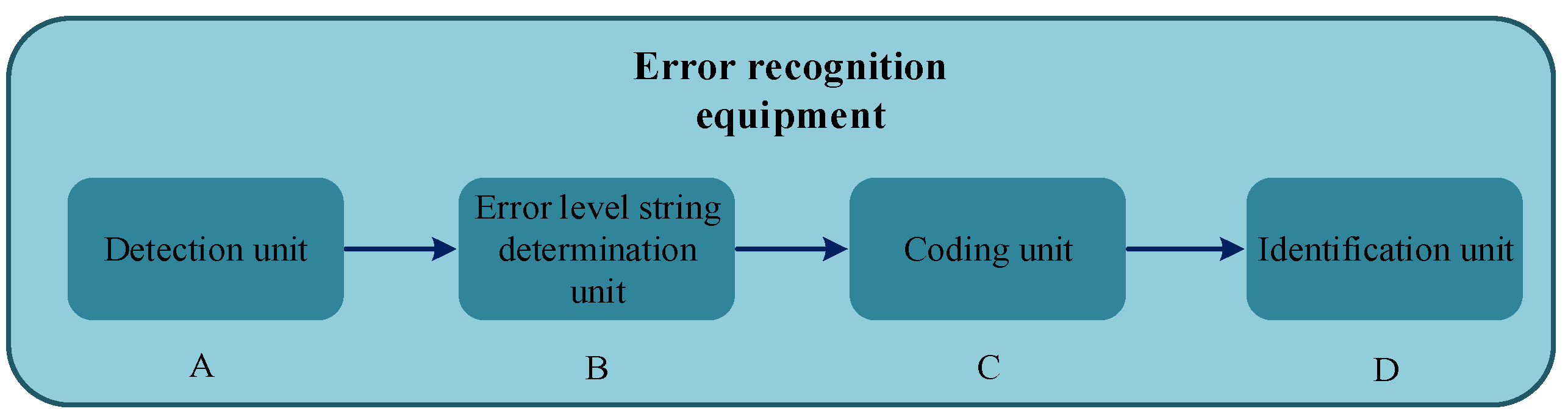
2.2. Hamming Information Representation of Deviant Events

Failure information is expressed for the MDF continuous hot press deviation fault type, and the error signal data flow using the Hamming coding method is shown in Figure 1, and the process of the reliable transmission of the error state of the plate shape guiding control system and error identification is as follows:
  • Error detection with Hamming code [25] coding;
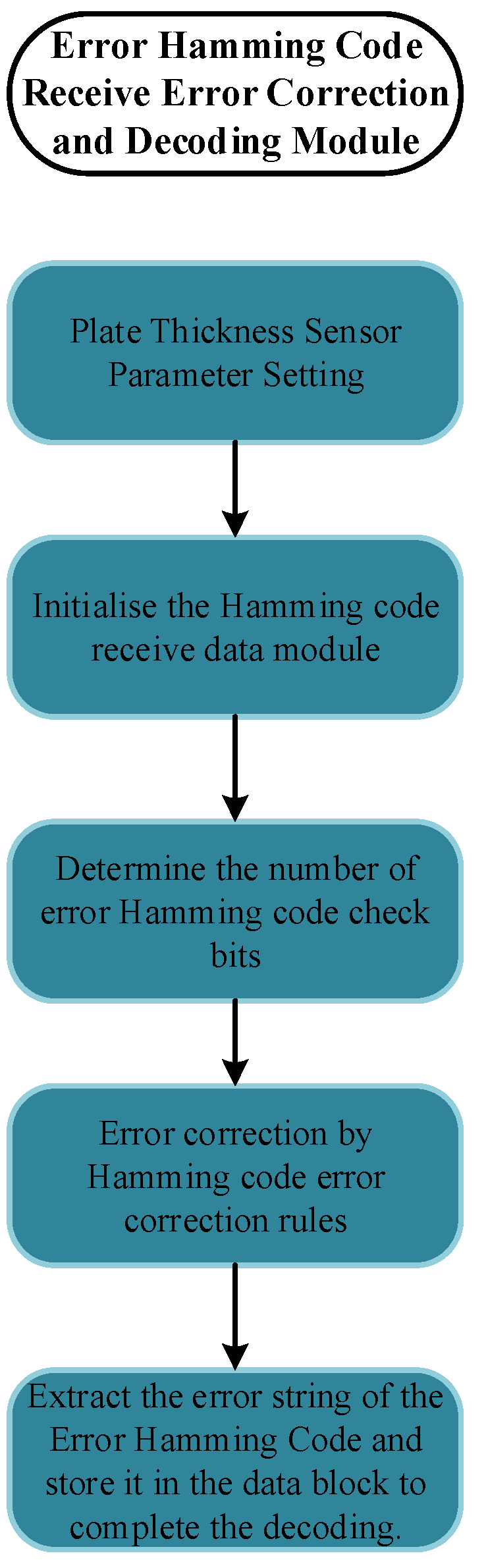
  • Reliable transmission (with error correction capability and the Hamming code error correction algorithm);
  • The identification and restoration of error states (the extraction of error state code from the Hamming code, decoding process, and programmer flow chart);
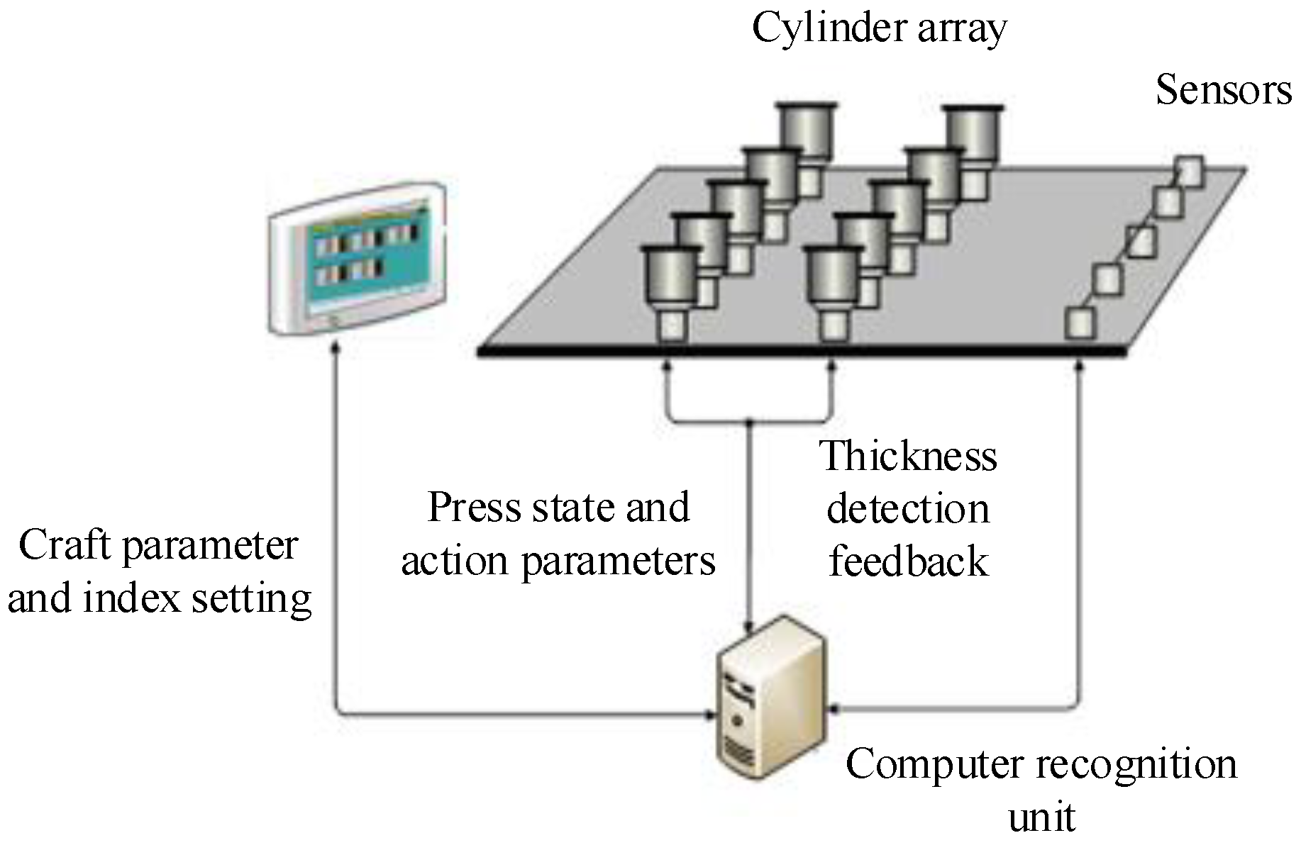
  • Multi-sensor fusion to restore the type of plate shape deviation and deviation level (by three thickness detection assembly combination state word);
  • Deducing collaborative control decisions.
The error recognition system designed and implemented for continuous flat plate thickness is shown in Figure 1, and the error recognition system includes the following: a detection unit A, which is used to detect the error information of the cluster control system; the error level string determination unit B, which is used to determine the error level string of the cluster control system based on the detected error information; the coding unit C, which is used for obtaining a coded error Hamming code by the string of error equivalence numbers; and the identification unit D, which is used to identify the channel in which the error occurs in the cluster control system based on the encoded error Hamming code.
The detection unit A can capture the system output by integrating the corresponding one or more sensors, and obtain error information by the difference between the system output and the desired value. The error level string identifier unit B can compare the error information with each of the predetermined error level reference ranges by setting a comparator, determining the error level reference range in which the error information falls, and then determining the value of the error level corresponding to the error level reference range as “1” and the value of the remaining error levels as “0”, thereby obtaining a string of error level numbers in which the error grades are predetermined and can be obtained based on empirical “AND/OR” expected values, or can be determined by the means of a test.

2.2.1. Deviation Information Encoder Design

The encoding and error correction decoding functions are completed sequentially as shown in Figure 2 and Figure 3, which are the flowcharts for encoding and error correction decoding, respectively in Table 2.
When each bit of the error level string is 0, which indicates that there is no error that needs to be adjusted, the error level string that is all 0 can be specified as a judgment criterion B0 for the occurrence of an error, and when there is an error that needs to be adjusted, at most 1 bit of the error level string Be will change from 0 to 1, which can be considered as a 1-bit error in the judgment criterion B0. Accordingly, in the error recognition method, the error level string is encoded by Hamming encoding, and the error Hamming code formed by the encoding includes each bit in the encoding bit of the error level string, and each bit in the ECW encoding bit.

2.2.2. Deviation Information Encoder Design

Through the execution of the above code, the detection system can identify the number of channels in which an error occurs by transmitting only N W S error status word coding bits at the receiving end in the encoded error Hamming code. By encoding the error level strings in the above mention error level strings in a Hamming code and identifying the channels with errors in the cluster control system on the basis of the encoded error Hamming code, a more accurate identification of the errors can be achieved compared to the existing error identification techniques for cluster control systems.
The MDF continuous hot press fault diagnosis and corrective control system is mainly for the MDF continuous hot press process of quality control. Taking the FMEA concept method will be necessary for the potential failure mode analysis of the fault information, and ultimately through the PLC system for the diagnosis and identification of failure modes, the identification of the deviation level through the corrective function will be possible to achieve the ultimate goal, as shown in Figure 4:

3. Event Triggering Control of Plate Deviation in Continuous Hot Pressing of MDF

Triggering Control Method of MDF Plate Shape Deviation Event

The type of deviation is defined as an event, and the process of making a decision on an event with a fault type is an event triggering [26,27].
In the MDF continuous hot-pressing process, the pressure-based event-triggered control strategy of the plate hot-pressing thickness preservation stage, if the pressure is kept within a certain range, the density of the fiberboard does not have much impact, and the plate thickness can be dealt with in post-processing; that is to say, the pressure is working in a bounded interval, and the pressure can be adjusted without continuous adjustment if it meets the design requirements. Therefore, it is possible to design a trigger control strategy for the pressure.
The event-triggering steps are as follows: first, set up the event-triggering mechanism (ETM) [28,29] and judge the event triggering by monitoring the error of the measurement status. That is, when the pressure tracking error is larger than the threshold, the controller should be continuously updated, and the current state information should be broadcasted to the adjacent hydraulic cylinders in the directed communication topology and the pressure adjustment is initiated to converge. Obviously, the event-triggered distributed relative pressure concerted control strategy is to replace the traditional continuous distributed control with the control state only when the triggering moment is determined.
Consider a multi-intelligent system consisting of N followers (numbered 1, …, N) and a leader (numbered 0), then there are
x ˙ i ( t ) = A x i ( t ) + B u i F ( t ) , i = 1 , , N x ˙ 0 ( t ) = A x 0 ( t ) + B u 0 ( t )
where x i ( t ) R n and u i ( t ) R m are the state of the follower i and the output of its controller, and x 0 ( t ) R n and u 0 ( t ) R m are the state and output of its controller, respectively. A and B are the constant matrices with suitable dimensions.
If the controller of the i th follower operates with a malfunction, which leads to inconsistency between its output u i F ( t ) and the input u i ( t ) , the u i F ( t ) is expressed as follows:
u i F ( t ) = θ i ( t ) u i ( t )
where θ i ( t ) R indicates the degree of an actuator failure, which is called failure factor, and satisfies 0 < θ _ i θ i ( t ) 1 with a lower bound θ _ i that is an unknown constant. It is obvious that the controller of the ith follower is in normal operation when θ i ( t ) = 1 .
In this section, the input of the leader is set to 0, i.e., u 0 ( t ) = 0 , and the consistency of the plates with actuator partial failure fault information is investigated under this condition. Firstly, the adaptive fault-tolerant controller for the i th follower is designed as follows:
u i ( t ) = c ^ i K ξ ^ i ( t ) , i = 1 , , N , ξ ^ i ( t ) = j = 1 N a i j ( x ^ i ( t ) x ^ j ( t ) ) + a i 0 ( x ^ i ( t ) x ^ 0 ( t ) ) ,
where K = B T P is a gain matrix, P > 0 , x ^ i ( t ) = e A ( t t l i ) x i ( t l i ) , t [ t l i , t l i + 1 ) denotes the estimate state of x i ( t ) , and t l i , l N is the triggering moment for the l th transmission of x i ( t ) from agent i to its neighbors, and the x ^ i ( t ) adjusts to x i ( t l i ) at the moment t l i . It is noticed that in this section u 0 ( t ) = 0 , which means x ^ 0 ( t ) = e A t x 0 ( t ) and the leader just transmits its initial state x 0 ( 0 ) to its neighbors at the initial moment.
Further, the measurement error is defined as e x i ( t ) = x ^ i ( t ) x i ( t ) , t [ t l i , t l i + 1 ) and e c i ( t ) = c ^ i ( t ) c i ( t ) , t [ T , T l + 1 i ) , on the one hand, and the sequence of triggering moments { t l i } of the transmission state x i ( t ) is determined by the following event-triggering mechanism
t l + 1 i = inf { t > t l i : f 1 i 0 } ,
where t 0 i = 0 and the trigger function f 1 i ( t ) is designed as follows:
f 1 i ( t ) = d i ( t ) c ˜ i ( t ) e x i T Φ e x i ( t ) ξ i T ( t ) Φ ξ ^ i ( t ) υ i e u i t , d ˙ i ( t ) = γ 2 i [ c ˜ i ( t ) e x i T ( t ) Φ e x i ( t ) ε 2 i ( d i ( t ) 1 ) ] ,
The starting value of d i ( t ) satisfies d i ( 0 ) 1 , c ˜ i ( t ) = c ^ i ( t ) + j = 1 N a i j c ^ j ( t ) , υ 1 , u i , γ 2 i , and ε 2 i are all positive constant. The i th follower does not transmit the current state to its neighbors until the trigger function f 1 i ( t ) is no longer negative, while e x i ( t ) is reset to zero. On the other hand, the sequence of triggering moments { T l i } for transmitting the adaptive gain c i ( t ) is determined by the following event-triggering mechanism:
T l + 1 i = inf { t > T l i : f 2 i ( t ) 0 } ,
where t 0 i = 0 , and the form of the trigger function is f 2 i ( t ) = e c i ( t ) σ i , σ i > 0 . Through this triggering mechanism it is known that when the adaptive gain c i ( t ) grows or decays no longer below the threshold σ i , c ^ i ( t ) will be updated to the current value of c i ( t ) , e c i ( t ) will be reset to 0 accordingly, while the neighbors of the follower i receive the latest transmission of c i ( t ) .
To compensate for the effect of the non-zero input u 0 ( t ) , the adaptive fault-tolerant controller with the follower i in the above section is modified:
u i ( t ) = r ^ i ( t ) ( K ξ ^ i ( t ) + g i ( K ξ ^ i ( t ) ) , i = 1 , , N , r ˙ i ( t ) = γ 1 i [ ξ i T ( t ) Φ ξ ^ i ( t ) + K ξ ^ i ( t ) ε 1 i ( r i ( t ) 1 ) ] ,
where r ˜ i ( t ) denotes the latest transmission value of the adaptive gain r i ( t ) , i.e., r ^ i ( t ) = r i ( T l i ) , t [ T , T l i + 1 ) , and the initial value of r i ( t ) satisfies r i ( 0 ) 1 . The rest of the variables and parameters are the same as in the previous section, and the leader’s trigger function f ¯ 10 ( t ) is designed as follows:
f ¯ 10 ( t ) = e x 0 T ( t ) Φ e x 0 ( t ) + K e x 0 ( t ) υ 0 e u 0 t ,
And the followers’ trigger functions f ¯ 1 i ( t ) , t = 1 , , N are designed as follows:
f ¯ 1 i ( t ) = h i ( t ) r ˜ i ( t ) ( e x i T Φ e x i ( t ) + K e x i ( t ) ) ξ i T ( t ) Φ ξ ^ i ( t ) υ i e u i t h ˙ i ( t ) = γ 2 i [ r ˜ i ( t ) ( e x i T Φ e x i ( t ) + K e x i ( t ) ) ε 2 i ( h i ( t ) 1 ) ] ,
The initial value of h i ( t ) in (9) satisfies h 0 ( t ) 1 , r ˜ i ( t ) = r ^ i ( t ) + j = 1 N a i j r ˜ j ( t ) , υ 0 > 0 , μ 0 > 0 , and the rest of the variables and parameters are the same as in (10). The moment of transmission of the adaptive gain r i ( t ) is determined by the following event-triggering mechanism:
T l + 1 i = inf { t > T l i : f ¯ 2 i ( t ) 0 } ,
where the trigger function f ¯ 2 i ( t ) is denoted by f ¯ 2 i ( t ) = e r i ( t ) σ i = r ^ i ( t ) r i ( t ) σ i .
Having considered the multi-intelligent body system and the matrix of event-triggered controllers to satisfy the above conditions, each intelligent body can exclude the occurrence of Zeno behavior under the proposed event-triggered controllers and the designed adaptive event-triggered conditions by proving that there exists a positive lower boundary between any two adjacent event-triggered moments.
Proof. 
the upper-right Dini derivatives of the state error e i ( t ) = r ˜ i ( t ) r i ( t ) can be measured for any time t [ t l i , t l i + 1 )
D + e i ( t ) e ˙ i ( t ) = r ˙ ˜ i r ˙ i ( t ) A e i ( t ) + μ ¯ i σ ¯ B ξ ˜ i ( t ) + h i ( ξ ˜ i ( t ) ) + L C δ i ( t )
where ξ ˜ i ( t ) = K j = 1 N σ ^ i j ( t k i ) a i j ( r ˜ i ( t k i ) r ˜ j ( t k j ) ) and k = arg max k { t k j t k j < t } , and the solution of (12) when e i ( t ) = 0 and δ i ( t ) = 0 is the following:
e i ( t ) + t k i t u ¯ i σ ¯ B e A ( t s ) ξ i ( t ) d s + t k i t u ¯ i σ ¯ B e A ( t s ) h i ( ξ i ( t ) ) d s 2 u ¯ i σ ¯ B A [ e A ( t t k i ) 1 ] ξ i ( t )
Consider the following Lyapunov function V ( t ) :
V ( t ) = ϕ T ( t ) ( I N Q ) ϕ ( t )
where Q > 0 so V ( t ) > 0 , and the time derivative of V ( t ) is
V ˙ ( t ) = ϕ T ( t ) ( A T Q + Q A H ¯ p 2 Q B B T Q ) ϕ ( t ) ϕ T ( t ) ( H ¯ p 2 Q B B T Q ) e t ε min ϕ T ( t ) e T ( t ) ( H ¯ p 2 Q B B T Q ) ρ ¯ 1 ξ i ( t ) 2 + 2 ρ ¯ 2 e ( t ) ξ i ( t ) + ρ ¯ 3 e ( t ) 2 ε min 2 ϕ T ( t ) ϕ ( t ) ρ ¯ 1 ξ i ( t ) 2 + 2 ρ ¯ 2 [ 1 2 ρ e ( t ) 2 + ρ 2 ξ i ( t ) 2 ] + ρ ¯ 3 e ( t ) 2 ε min 2 ϕ T ( t ) ϕ ( t ) i = 1 , i h ( p ) N [ ( 1 δ ) ( ρ ¯ 1 ρ ¯ 2 ρ ) ξ i ( t ) 2 ] ε min 2 i = 1 , i h ( p ) N ϕ i T ( t ) ϕ i ( t )
where h ( p ) is a set of λ p i . Based on the above equation, it can be seen that lim x Φ i ( t ) = 0 . When lim x Φ i ( t ) = 0 , V ( t i ) , i = 1 , , N is a finite sequence; it can be noticed by Cauchy’s convergence criterion that
t S 0 t S 1 [ V ˙ ( t ) ] d t + + t S W S 1 t S W S [ V ˙ ( t ) ] d t < α
For each integral term, there is the following:
t S i t S i + 1 [ V ˙ ( t ) ] d t ε 2 t S l t S l + ς S h ( σ ( t S i ) ) Φ i T ( t ) Φ i ( t ) d t
Therefore,
α > ε 2 S h ( σ ( t S i ) ) [ t S 0 t S 0 + ς Φ i T ( t ) Φ i ( t ) d t ] + + t S W l t S W S 1 + ς Φ i T ( t ) Φ i ( t ) d t
Time interval [ t S , t S + 1 ) contains a finite number of topology switches and w S , s = 1 , 2 , is finite, thus
lim x t t + ς [ l h ( σ ( t S 0 ) ) Φ i T ( ϵ ) Φ i ( ϵ ) d ϵ = 0 , l = 0 , , w S 1
The following equation holds; it is obvious that
lim x t t + ς [ l h ( σ ( t S 0 ) ) Φ i T ( ϵ ) Φ i ( ϵ ) + + l h ( σ ( t S i ) ) Φ i T ( ϵ ) Φ i ( ϵ ) ] = 0
Considering that the communication topology is connected during the time [ t S , t S + 1 ) interval, Equation (20) can be transformed into the following:
lim x t t + ς [ i = 1 N a i Φ i T ( ϵ ) Φ m ( ϵ ) ] d ϵ = 0
where a i > 0 , i = 1 , 2 , , N , the Lyapunov function V ( t ) > 0 and V ˙ ( t ) < 0 according to Equations (19) and (20), thus the ϕ i ( t ) is bounded, and lim t ϕ i ( t ) = 0 based on Barbalat’s lemma. The multi-agent track problem can be solved well.
The event-trigger-based state calming function is designed considering the continuity of the MDF continuous hot-pressing system:
u ( t ) = R x ( t ) , t [ m T , ( m + θ ) T ) 0 , t [ ( m + θ ) T , ( m + 1 ) T )
where m Z 0 + , R q × n denotes the gain of the controller, and in order to further reduce the burden of triggering information generated during the control process, the event-triggering strategy is introduced into the cyclic intermittent control, and { t m k } is defined as a trigger moment sequence which satisfies the following:
t m 0 = m T t m k + 1 = inf { t ( t m k , ( m + θ ) T ) : h ( t , x ( t ) > 0 ) } , k { 0 , 1 , , k max ( m ) }
where h ( t ) is the trigger function and k max ( m ) is the maximum number of triggers in the m th control fetch. Let t m k max ( m ) + 1 = ( m + θ ) T ; clearly, there will be [ m T , ( m + θ ) T ) = k = 0 k max ( m ) [ t m k , t m k + 1 ) .
When t [ m T , ( m + θ ) T ] , we define the sequence of states corresponding to the triggering moment as { x ( t m k ) } such that the control u ( t ) remains constant in strength across two triggering events. Then, the calming function is redefined as follows:
u ( t ) = R x ( t m k ) , t [ t m k , t m k + 1 ) , k { 0 , 1 , , k max ( m ) }       0 ,       t [ m T , ( m + θ ) T ] , m Z 0 +
The closed-loop control system for the continuous hot pressing of MDF under intermittent event-triggered control can be written as follows:
x ( t ) = A x ( t ) + B f ( x ( t ) ) + B τ g ( x τ ( t ) ) + C R x ( t m k ) t [ t m k , t m k + 1 ) , k { 0 , 1 , , k max ( m ) , m Z 0 +
By defining the measurement error ε ( t ) generated by the plate deviation
ε ( t ) = x ( t m k ) x ( t ) , t [ t m k , t m k + 1 )
The system under the control described in (26) became the following:
x ( t ) = ( A + C R ) x ( t ) + B f ( x ( t ) ) + B τ g ( x τ ( t ) ) + C R ε ( t ) , t [ t m k , t m k + 1 ) x ˙ ( t ) = A x ( t ) + B f ( x ( t ) ) + B τ g ( x τ ( t ) ) , t [ m T , ( m + θ ) T )

4. Grain Calculation-Based Correction Control Methods

4.1. Grain Calculation Correction Method

There is a close relationship between the triggering control of MDF continuous hot pressing deviation events and three-way decisions [30,31]. In the MDF production process, continuous hot pressing is an important part, which plays a vital role in the quality and performance of the sheet. However, due to factors such as production process parameters, equipment conditions, and raw material characteristics, deviation events during hot pressing sometimes occur, leading to a decrease in product quality or failure to meet the expected standards. When a deviation event occurs in the hot-pressing process, it is necessary to take the main support decision in a timely manner, i.e., stop the hot-pressing operation immediately, analyze and diagnose the problem, and adjust the relevant parameters or carry out equipment maintenance to ensure product quality. Using the event-triggered control method combined with the three-way decision-making scheme to finally confirm the type and level of deviation, correct corrective solutions and measures can be made in time.
According to the definition of the upper and lower approximation sets of the subset X U , the whole domain U can be divided into three disjoint regions: the positive domain POS ( X ) , the boundary domain BND ( X ) , and the negative domain NEG ( X ) [32], which are defined as follows: a positive rule POS ( X ) generated by the positive domain corresponds to an acceptance decision, a negative rule generated by the negative domain NEG ( X ) corresponds to a decision, and a boundary rule generated by the boundary domain BND ( X ) makes a delayed decision, i.e., it does not give a decision solution immediately.
The affiliation level of the three-way decision making is the following:
μ A = P ( X | [ x ] ) = X [ x ] [ x ]
where the [ x ] is the base of a set and P ( X | [ x ] ) denotes the probability of the conditions that produce such deviations, so the corresponding three domains are as follows:
POS ( X ) = { x U | P ( X | [ x ] ) = 1 } BND ( X ) = { x U | 0 < P ( X | [ x ] ) < 1 } NEG ( X ) = { x U | P ( X | [ x ] ) = 0 }
From Equation (28), it follows that those objects with non-zero and non-one affiliation function values are classified into the boundary domain, where a looser categorization may make more sense in practical production. If the conditional probability of an object is large enough, then it is classified as positive; similarly, if the conditional probability of an object is small enough, then it is classified as negative. The decision is thus made to replace 0 and 1 in Equation (29) by introducing a pair of thresholds α and β , where 0 β < α 1 . The positive, bounded, and negative domains of this ( α , β ) can be defined by the set of the upper and lower approximations to the ( α , β ) as
POS ( α , β ) ( X ) = { x U | P ( X | [ x ] ) α } BND ( α , β ) ( X ) = { x U | α < P ( X | [ x ] ) < β } NEG ( α , β ) ( X ) = { x U | P ( X | [ x ] ) β }
When α = 1 , β = 0 in Equation (29). The equation is transformed into the Pawlak rough set model. In real production, the thresholds α and β represent the risk measures in the decision-making process; therefore, estimating a reasonable value of both becomes very important in the actual decision-making individual.
In order to determine the type of deviation in the MDF continuous flat press process, adopt the 5 × 5 array of press cylinders with fixed thickness section in the array 37 × 5 of the MDF continuous hot press as the target for testing, and conduct decision-making analysis on the type of deviation through the granular computing method to construct a three-way decision-making model. The decision making, as shown in Figure 5, indicates that the secondary determination and decision making will only be generated in the case of the band intervention quantity; and the target after decision making is finally represented in the form of the decision-making matrix.
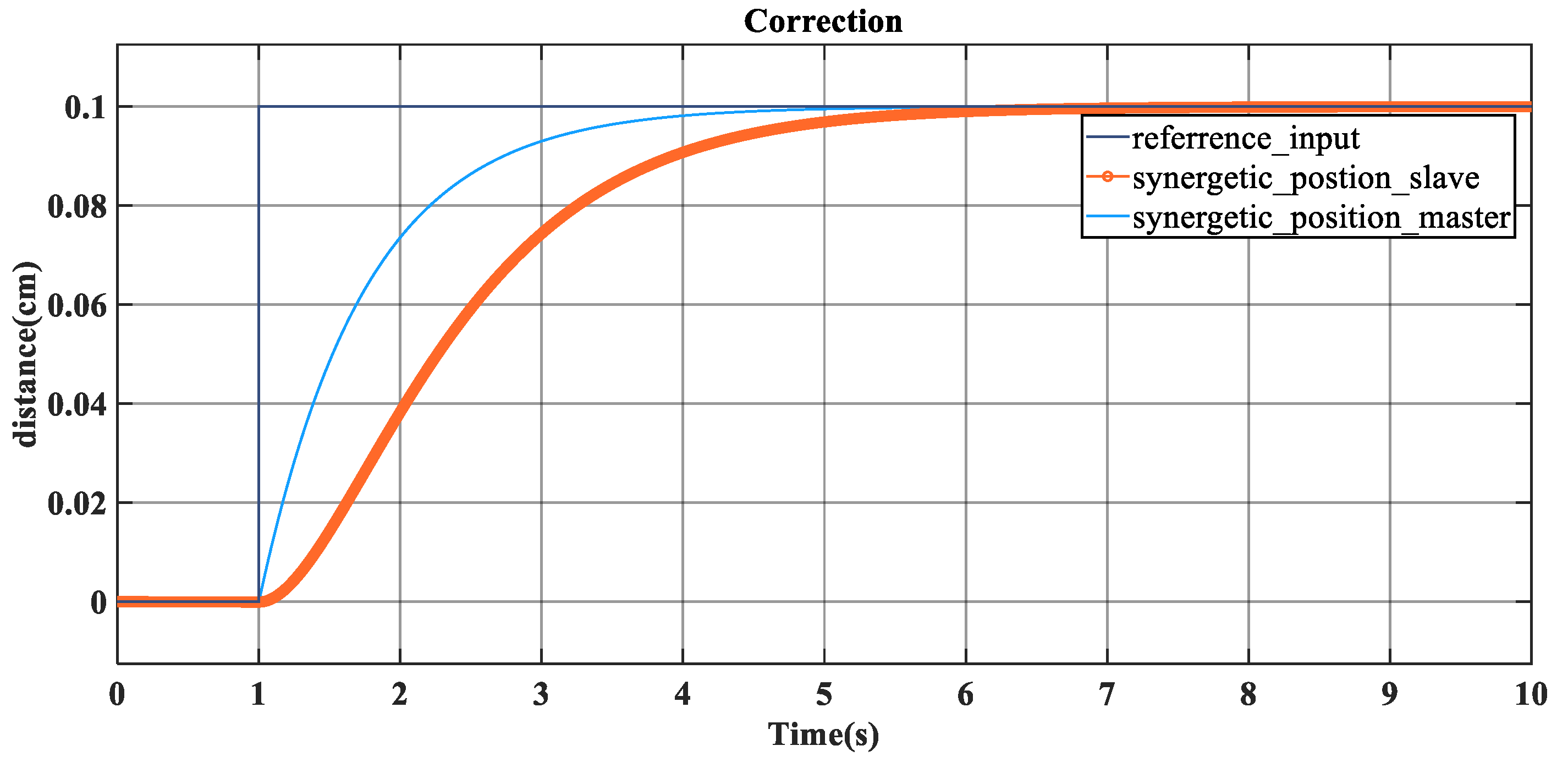
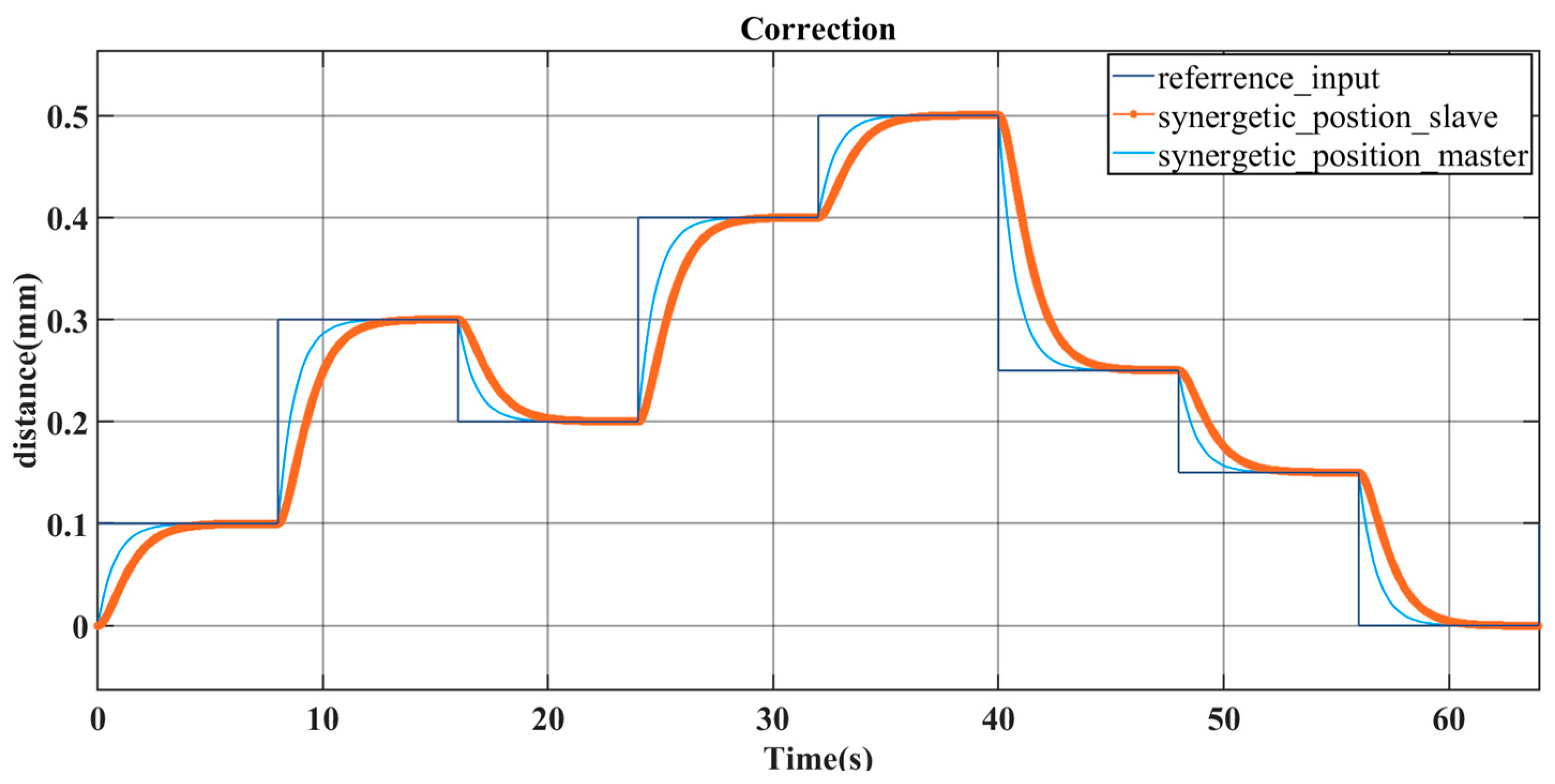
  • Position–position output mode: The system consists of a master and several slaves. The master is responsible for executing a specific function. When the input signal changes, the master outputs the displacement. The slaves calculate and output the corresponding displacement according to the position sensor of the master, so as to achieve synchronized movement, respond quickly to changes in the external environment, and maintain high accuracy.
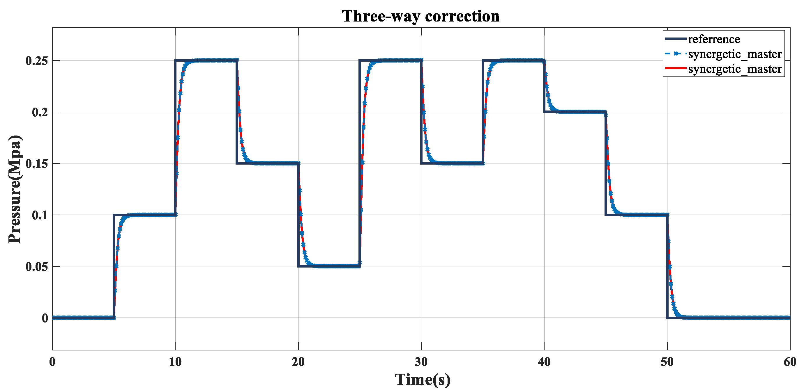
  • Pressure–pressure output mode: On the basis of position–position output mode, the master end also outputs pressure, which increases the requirements for system stability and adaptability. The slave end receives the feedback data from the pressure sensor of the master end, adjusts its own pressure output, maintains the same response speed and accuracy as that of the master end, and ensures the stable output of the system, even under complicated working conditions.
  • Position–pressure output mode: Combining position and pressure output, the slave terminal carries out pressure output according to the partial pressure value of the position sensor of the master terminal. The controller is required to respond accurately to the pressure value feedback from the master and slave and make corrections according to the position–pressure relationship to ensure that the final output meets the standards, adapts to various environments, and maintains high performance and accuracy.
Through the description of the above three-way decision-making basic theory [33], master–slave [34] synergetic simulation is carried out under a given square wave signal, and the results are shown in Figure 5, Figure 6, Figure 7 and Figure 8, which are represented as the output effect of the single-grain cylinder and multi-group cylinder grain structure for position–position and pressure–pressure, respectively, for observing the tracking effect between the master and slave.
Figure 5 shows the single-cylinder pressure correction under three-way decision making, and it can be seen that the tracking is basically consistent after 2 s, which is consistent with the given signal, the tracking effect is better, and the auto-correction is completed in the tracking process.
As shown in Figure 8, it can be clearly observed that the pressure value in the vertical coordinate does not represent the actual measured absolute pressure level, but rather a specific difference that is required to make a precise adjustment. By analyzing the variable square wave signals, it can be seen that the system has an excellent following performance for adjustments between different pressures. This ensures that the system can monitor and respond to changes in the production conditions in real-time, enabling efficient and reliable online adjustment mechanisms during continuous production. This dynamic adjustment capability results in a more stable production process, reducing the potential problems caused by production fluctuations and improving product quality and productivity.
Therefore, the event-triggered calming method is the deviation fault information determination of MDF continuous hot pressing; first of all, the research object is to express the fault event information in the FMEA table completely and make a decision analysis about it. The fault decision information of MDF continuous hot pressing is listed as shown in Table 3, and the matrix data in the table are expressed as the decision matrix of different deviation levels, and the triggered event analysis is used to make a control decision mode mapping matrix for each case of the fault information event of each case of the deviation fault information generated in the process of MDF continuous hot pressing. The types of deviation are expressed from left to right through the matrix information in turn, and the corresponding control mode decision mapping is made for each form to realize the distributed collaborative control among the MDF continuous flat press cylinder groups. The triggering mode of the deviation event information is shown in Figure 9.
Figure 9 represents the event-triggered control analysis diagram for the plate deviation detection, which is triggered by the current deviation event to the state t-1 of the previous moment, and is carried out to determine the fault type information after triggering, so as to carry out the decision making, and the decision making is outputted to the pressure angle in the big feedback system.
The event is triggered by the position of the fixed thickness section of the pressure cylinder group of five sensors to detect the position and pressure information, respectively, represented by S. The deviation type decision matrix derived from the method of three-way decision making is shown in Table 3, Table 4 and Table 5, where the numbers in the table represent different meanings, of which 3+, 3+++ represents the different degree of the control mode 3 due to the relatively large deviation in the MDF which can not be regulated with too much intensity, so there will be many different degrees of control mode for each control mode. To ensure the accuracy of correcting the deviation and fine-tuning, S indicates the sensor, the digital front bit represents the position of the sensor, and the back bit represents the number of levels of information constructed by the sensor, and through the different values of the five sensors, viewed as five points, they will be connected to the point. This can be a preliminary determination of the type of deviation, which indicates the amount of the thickness of the intervention and the intervention value of the positive and negative points in the thickness of the demand for different situations in accordance with the positive and negative interventions, which can be added or reduced. In terms of the value of the pressure intensity of the adjustment (increase or decrease), the more the plus or minus sign, the greater the intensity.
As described in Table 3, the three-branch decision-making method determines that S 10 S 20 S 30 S 40 S 50 is a non-deviation type, in which case the 4-4-2-4-4 control mode is used to ensure that the thickness is maintained during the continuous flat-pressing process by regulating the pre-pressure. S 15 S 25 S 35 S 45 S 55 is a thickness deviation of five levels; at the time of the 4-3-2-1-4 control mode of decision making, the thickness of the plate needs to adjust the pressure intensity P + + and increase the amount of position control intervention D + + to achieve the required thickness requirements.
S 10 S 20 S 31 S 41 S 52 represents the deviation type of the right slope and the level of thickness deviation of level 1, S 13 S 23 S 34 S 44 S 55 represents the deviation type of the right slope and the level of thickness deviation of level 3 and the right slope of level 5, and the two digits after S, which indicate the position of the sensor and the number of deviation levels, and the control mode is adopted to control the decision making as 1-3-1-1-4. S 15 S 25 S 34 S 44 S 52 represents the type of deviation as the left slope, with the grades of the thickness deviation of 2 and the right slope of 5. The control decision making is carried out by using the control model of 4-3-1-2-4, and pressurization control is carried out in the first column with the design pressure intensities of P + and P + + .

4.2. Ruling out MDF Continuous Hot Pressing Deviation Events Triggering Zeno Behaviour

At different levels of the granular structure, the particles become finer as the amount of information increases. At lower levels, where there is less information and the particles are coarser, decisions can be made quickly, which can reduce the cost of the decision-making process, although it may increase the cost of the decision outcome. At higher levels, on the other hand, with the influx of more information, the particles become finer, which may lead to a less costly decision outcome, but a corresponding increase in the cost of the decision process. Therefore, the key is to make the right decision at the right level. In a dynamic three-way decision-making process at multiple levels, changes in the decision-making information system lead to a dynamic update of the loss function matrix, which in turn affects the setting of the threshold pair ( α i and β i ). Therefore, the problem of optimally setting the threshold pair should be considered at each granular level. In the lower granular layers of sequential three-way decision making, a certain amount of decision errors may be tolerated to minimize the cost of the decision-making process.
Take the slope deviation as an example and calculate the optimal decision scheme for deviation; the deviation level information is granulated, and the expression of the deviation information after granulation is the synergy matrix between D and P embodied in Table 1, Table 2, Table 3, Table 4, Table 5 and Table 6, and according to the type of the corresponding matching, it appears that at this time, the deviation is the slope level 3, which is defined as the granulation of the first level of the slope failure and is calculated as follows:
P O S D P = P O S ( 0.8 , 0.2 ) D P ( M 04 ) = ϕ B N D D P = B N D ( 0.8 , 0.2 ) D P ( M 04 ) = U N E G D P = N E G ( 0.8 , 0.2 ) D P ( M 04 ) = ϕ
P O S D P is the empty set indicating that the current determination of the slope state does not satisfy the upper boundary domain range, and M 04 is the decision matrix information for the slope case derived in [8].
Calculate the fault information of the second layer as shown in Equation (31):
P O S D P 2 = P O S ( 0.8 , 0.2 ) D P 2 ( M 04 ) = P D P P P D D + P + + P P D D + P + D + P D D + P + + P P P D P P P B N D D P 2 = B N D ( 0.8 , 0.2 ) D P 2 ( M 04 ) = ϕ N E G D P 2 = N E G ( 0.8 , 0.2 ) D P 2 ( M 04 ) = P D P P P D D + P + + P P D D + P + D + P D D + P + + P P P D P P P
Compute the particle information for the third layer:
P O S D P 3 = P O S ( 0.8 , 0.2 ) D P 3 ( M 04 ) = ϕ B N D D P 3 = B N D ( 0.8 , 0.2 ) D P 3 ( M 04 ) = P D P P P P D D D P P D D D P P D D D P P D P P P N E G D P 3 = N E G ( 0.8 , 0.2 ) D P 3 ( M 04 ) = P D P P P D D + P + + P P D D + P + D + P D D + P + + P P P D P P P
The decision to compute all three layers is as follows:
P O S D P 3 = P O S D P 1 P O S D P 2 = P D P P P D D + P + + P P D D + P + D + P D D + P + + P P P D P P P B N D D P 3 = B N D D P 2 B N D D P 3 = ϕ N E G D P 3 = N E G D P 2 N E G D P 3 = P D P P P D D + P P P D D + D + D + P D D + P P P P D P P P
The final determination is obtained by calculating the grains of the three layers as follows:
P O S F i n a l D P = { Slope L e v e l 1 : ϕ , l e v e l 2 : P D P P P D D + P P P D D + D + D + P D D + P P P P D P P P , l e v e l 3 : ϕ } B N D F i n a l D P = ϕ N E G F i n a l D P = { Depression l e v e l 2 : P D P P P D D + P P P D D + D + D + P D D + P P P P D P P P }
The entire system will use the appropriate communication protocols according to the real-time requirements. In the field, since the control cannot be delayed, the MPI or PROFIBUS communication protocols determined by the corresponding time are selected. The MPI protocol is mainly used for exchanging data between simple PLCs in foreign countries. The AS Interface can be used to realize the fieldbus connection of the devices. The Ethernet protocol with large information transfer can be used between the monitoring and management levels. Although the response time for transmitting information commands is uncertain, it is sufficient for data backup.
The hot press plate thickness is defined as 18 mm. This matrix decision is based on the multi-sensor information fusion operation. Control media volume acts on the analog power supply terminals, and the DSC industrial computer interface shows the output dynamics of the array of hydraulic cylinders as shown, with each actuator displacement output and pressure output such as matrix D and P as in Equations (35) and (36).
D a r r a y = 18.02 18.02 18.02 18.02 18.02 18.02 18.02 18.02 0 17.99 17.99 17.99 17.99 17.98 17.99 17.99 17.99 18.00 17.99 17.99 17.99 17.99 17.99 17.99 17.99 17.99 0 18.03 18.03 18.03 18.03 18.03 18.03 18.03 18.03 18.01 18.03 18.03 18.03 18.03 18.03 18.03 18.03 18.03 0
P a r r a y = 18.00 18.00 18.00 18.00 18.00 18.00 18.00 18.00 0 17.99 17.99 17.99 17.99 17.98 17.99 17.99 17.99 18.00 17.98 17.98 17.98 17.98 17.99 17.98 17.98 17.98 0 18.04 18.04 18.04 18.04 18.04 18.04 18.04 18.04 18.02 17.98 17.98 17.98 17.98 17.98 17.98 18.02 18.02 0
The results from the matrix show that the corrected deviation is basically in the production of the required 18 mm plate thickness, and tends to be stable, which confirms the effectiveness based on the particle calculation decision-making approach to correct the deviation.
The density is 850 kg/m3 and the pressing speed is 959 mm/s. In the simulation experiments, the particle change point is marked according to the synergy rule of the decision matrix, and the plate deviation effect is generated by the synergistic control of the response in the dynamic intersection interface. The positional particle information of the thickness deviation point is marked in the third group of press cylinders, which is divided into positional output and pressure output according to the intersection interface formed by the particle points.

5. Experiments and Tests

The deviation fault is judged as the thickness deviation type, and the position output effect diagram is shown in Figure 10a. The thickness of the plate is 18 mm, and the thickness difference ranges between plus and minus 0.20; the pressure field range shown in the figure is the range of the pressure intensities listed in the decision table; and the thickness difference fluctuates over a small range, and the deviation level is judged to be A-rated.
In the case where the thickness deviation is defined as A grade, the error is not big, and in the case of the plate classified as A grade, through the particle information marked by the array of the pressure cylinders, it can be known that the synergistic mode is five cylinders’ synergistic output in the 18 groups of the control mode of mode 2 to respond to the corresponding synergy. By adjusting the pressure values of the middle three groups of cylinders, the dynamic surface of the plate thickness tends to be flat.
In the failure mode analysis of the MDF continuous hot-pressed sheets, the groups 17–21 of the array of the pressure cylinders were located at the fixed thickness stage of the sheet. The vicinity of the pressure field where group 18 is located in Figure 10b generates different levels of pressure values, which are adjusted by the different intensities of pressure and designed intervention values. The range of position and pressure is adjusted under the thickness deviation, as shown in the figure where a field circle is formed within the range of the pressure field and position field where group 18 mm is located. Each group of pressure cylinders generates five field circles, indicating the pressure or position particle information at this point.
Specifically, the pressure output of all these pressurized cylinder systems is maintained around the level of 52 MPa, and the current simulation analysis of the controller design was carried out to examine the ability of the controller to track the cyclically varying signals by means of two pressure inputs, the step response and the square wave corresponding to it, and to compare it with a conventional PID. The response speed of the cooperative controller is slightly slower than that of the pseudo-differential feedback controller, which makes its transient performance smoother, avoids oscillations during the error elimination process, and realizes jitter-free regulation with a control accuracy of 3%. The master terminal realizes an independent output, which is not affected by the coupling of the slave terminal output.
Figure 10c shows the schematic diagram after thickness deviation correction, on which it can be clearly seen that the position where the groups 17–21 are located represents the output of the fixed thickness section. At the same time, the pressure coordination process between the hydraulic cylinder groups is reflected in the synergistic PID control output. By adopting the grain calculation method for deviation correction, it is possible to accurately measure the position of the pressure cylinders of the five cylinders at 17–21 speed. Based on the measurement results, it was found that the actual position of the plate thickness controlled by the hydraulic cylinders was approximately within the accuracy range of 18 mm.
As shown in Figure 11, from the angle of observation from the position output deviation variable particle information, the darker the color, the greater the position difference. Through the color bar on the number of information can be determined the deviation fault type for the thickness of the thickness deviation, the thickness of the 18 mm plate, and the thickness difference range of plus or minus 0.20. The range of pressure field shown in the figure is the range of the pressure intensity listed in the decision table, and the range of fluctuation of thickness difference is small.
This result fully proves that the deviation correction method is effective and reliable, indicating that the related positional deviation correction method plays a significant effect in improving the processing accuracy of the products.
According to Figure 12a, in the case where the deviation for the left slope is defined as A grade error and it is not too much under the circumstances listed as A grade plate, through the pressure cylinder array-labeled particle information, it can be known as the synergistic way for five cylinders’ synergistic output. In the 21 groups of five groups of positional field circles, the size of the field circles for the positional information of the adjustment of the intensity of the control mode of mode 3 and mode 0 for the corresponding response appear to be synergistic. Adjust the positional information of the five groups of pressure cylinders in the position field circle. By adjusting the pressure value of the middle three groups of pressure cylinders, the dynamic surface of the plate thickness tends to be plane.
As shown in Figure 12b, the left slope pressure output under the pressure field circle of the five groups of pressure cylinders is between the synergistic way, the pressure value is controlled at about 50 MPa, and the color bar 52–56 in the figure shows the pressure value interval fluctuations; the darker color represents the greater pressure here. With the use of the particle calculation method of correction, it can be seen that the position is in the 18.05 mm or so, and the data produced from the production site of the actual running value information provide at this time the plate thickness information. All tend to the same dynamic surface, and keep flat; at this time for the left slope after correcting the value and simulation experiment effect. In the 21 groups, mark five groups of pressure cylinder particle information so that it reaches the dynamic consistency to achieve the consistency of the plate. The red dots in the figure represent the distribution of the position field and pressure field, and the circles represent the range of the position field circle and pressure field circle in which the current deviation is located.
Figure 12c shows the dynamic interface of the left slope deviation correction, with the hot-pressing plate at the bottom and the plate surface at the top, and fifty-five percent of the press cylinders array grain structure model labeled as groups 17–21 (deviation type analysis diagram), which can be seen in detail in the diagram as the deviation type analysis diagram of the array grain structure model of the press cylinders of the groups 17 to 21. From the graph, it is easy to see that the faults that originally existed in the 18 groups of cylinders were effectively repaired and corrected after the advanced event-triggered grain calculation method was used for the corrective treatment. The repair of these faults not only restores the normal operation of the original equipment but also ensures that the dynamic surface of the plate remains relatively stable and avoids any possible fluctuations. In this way, any small deviations in the dynamic surface of the sheet can be adjusted in a timely and efficient manner, resulting in a smoothness that is consistent with the design criteria and maintained at the same level, thus ensuring the consistency and stability of product quality.
Figure 13a shows the position output under the right-slope deviation, with anomalous position data for the 17th set of rack numbers; these values show a significant range of fluctuations, specifically the particular value of 18.20 to 18.25 mm. More significantly, these thickness values are not evenly distributed and do not fall within the normal standard range, resulting in the so-called right-slope phenomenon. In addition, five of the racks in group 17 also exhibited the phenomenon of a positional field circle at the position of the press cylinders, which means that there is a partial fluctuation in the position. This phenomenon may affect the accuracy and stability of the machine and therefore requires sufficient attention in order to make the necessary adjustments and optimizations.
As can be seen in Figure 13b, the dynamic state of the system was significantly improved after the application of the synergistic master–slave correction method described in this section. It was found that the pressure field circles were abnormally clustered at location 3 (labeled 3, 4, and 5 in the figures) of the group 17 structure, creating a specific fault region. Further analysis and treatment are required to ensure the quality and reliability of the engineering design.
Figure 13c shows the effect of deviation correction for the right slope of the deviation type. It can be seen that the five sensors in the 17th group are adjusted according to the sequence of the 1-3+-1-1-4 control modes in Table 3, and the 3+ indicates that the intervention of the position is carried out in the position of the master cylinder, and the accompanying pressure generated from the cylinder will be adjusted accordingly with the pressure adjustment of the master cylinder with the control of the position of the master cylinder, and the automatic deviation correction is carried out to ensure that there is no overshooting, and the effect is obvious with the remaining four pressure cylinder positions.
Figure 14a,b show the positional pressure output under the depression deviation type, the pressure value anomalies are in the range of 55–55.5 MPa for the pressure intensity field circles generated in the groups 17, 19, and 21, with the largest fluctuations in the pressure values for the position 1 sensor and position 5 sensor in group 17. Therefore, the 4-3-1-1-4 control mode with the Leader-Following synergistic method of depression level 3 in the decision Table 3 needs to be used to regulate with a pressure regulation level of P++.
The MDF continuous hot press cylinder array synergistic approach cyber granular structure under recessed deviation, in a continuous press rack with 17 to 21 groups, feedbacks the type of deviation based on different positional information and pressure information. The pressure range in which the yellow area is located is between 55 and 55.5, which belongs to the moderate depression B level. In Figure 14, it can be seen that the pressure field circles are generated in the groups 17, 18, 20, and 21, respectively, with a field circle range of P++, and the depressions caused by the thinning of the plate thickness with high pressure.
For this kind of scene, the master–slave and Leader-Following methods are adopted to carry out the synergy between the cylinders, and the granular structure model is designed to trigger the event through the information after the deviation type determination, and the triggering method is the calming triggering, and the triggering function in the first section is used to act on the power actuator unit of the synergistic cylinders to form the granular structure model of the cylinder array to achieve the effect of the deviation correction.
Figure 14c shows the correction effect of the plate depression deviation after applying the grain calculation method for the correction process. It can be observed that compared with the phenomenon of the sudden increase in the pressure that appeared in Figure 14c, the data adjusted by the method have been significantly improved. The pressure values quickly return from an abnormal state to a more normal and stable range. This result clearly shows that the deviation correction method can effectively control the data information between the pressure cylinder position and the pressure during the actual operation, and realize the precise adjustment and control of deviation. In this way, the system performance is improved and the stability and reliability of the equipment’s operation is ensured.
Figure 15a shows the positional output of the bump deviation, which produces a synergistic array between the groups 17–21. The hydraulic cylinder number 3 in group 17 generates a pressure field circle, and the larger the field circle is, the higher the pressure is at this time. Similarly, when the pressure value fluctuates in the range of about 18.05, the deviation level at this time is bump A level.
Figure 15b shows the pressure under the type of bulge deviation; in group 17–21 racks, the pressure field circle of the position 3 sensor in group 17 fluctuates more. From the blue-colored data display, it can be seen that the pressure value of the No. 3 position in group 17 is the largest, 52.8 MPa, which leads to the bulge phenomenon. The situation after deviation correction is shown in Figure 15, respectively, in the groups 18, 19, and 20; the pressure of the No. 4 pressure cylinder position pressure is adjusted using the decision-making scheme derived from the method of particle calculation, and it can be seen that the adjusted pressure is consistent with the groups 17 and 21, which confirms the effectiveness of the deviation correction of the MDF plate shape in Figure 15c.
Table 4, Table 5, Table 6 and Table 7 present a detailed record of the MDF performance data for the March 2024 period based on a series of rigorous tests performed by Grecon’s sensor equipment used in the production process. These data cover a number of key performance indicators for MDF panels, including internal bond strength, static flexural strength, and surface bond density. In addition, the table includes the measurements of the moisture content and expansion of the finished panels, which are important for evaluating the physical properties of the panels and adapting them to different environmental conditions. This series of precise monitoring and analysis ensures the consistency and reliability of the product quality and provides valuable data for subsequent research and development.
The above table is the dynamic real-time data of the plate in the actual production; the density is basically maintained at about 650, the average value is 685.82, the average value of the surface density is 469.69, the current press speed is 670 mm/s, the thickness deviation is about 2.2, the average value of the internal binding strength of the MDF is 1.40, which ensures the completeness of the slab, and the current data are a more desirable state in the production.
Using the master–slave and Leader-Following correction methods, it can already be seen that there are some fluctuations in the plate thickness values, which can be quickly converted to a steady state, confirming the effectiveness of the correction methods.

6. Discussion

The study of the continuous flat pressing of wood–plastic composites (MDF) has always been a key topic in modern manufacturing. Especially in the stage of the “fixed thickness section”, it brings great challenges and complexity to the production process due to the typical deviations in the thickness, slope, depression, and bulge involved. In order to solve these problems, we propose an intervening three-way decision-making cooperative control method for the viscoelastic multi-field coupling-distributed agile control of the “fixed-thickness section” in the MDF continuous flat-pressing process. The method is designed to solve the complex problem of the “fixed-thickness section” in the MDF continuous flat-pressing process, including the typical deviations in the thickness, slope, depression, and bulge. The specific program includes the following key points:
  • It is innovative to redefine the single-terminal power unit of MDF hydraulic cylinders and adopt the grain structure approach to construct the distributed control grain structure intelligent perception model of a continuous press cylinder array.
  • The three-way decision-making idea is adopted to determine the uncertain deviation types and grades in the continuous hot-pressing process of MDF, and the correct adjustment program can be made in time so that the uncertain deviation types and grades in the boundary domain become controllable.
  • Based on the cyber granular computing technology, a three-way decision-making quality control method computing is proposed for the viscoelastic multi-field coupling-distributed agile regulation of the “fixed thickness stage” of the MDF continuous flat-pressing process.
The above solutions can obtain a better corrective effect, improve the product quality and the production of superior products, and better achieve the goal of MDF continuous hot pressing precision control to meet the needs of agile production.

7. Conclusions

An interventional three-way decision-making event-triggered cooperative control method is proposed for the viscoelastic multi-field coupled distributed agile regulation of the “fixed thickness section” in the MDF continuous flat-pressing process. The method is designed to solve the complex problem of the “fixed thickness section” in the MDF continuous flat-pressing process, including the typical deviations in the thickness, slope, depression, and bump. The event-triggered control method of board shape correction for wood-based fiber composites driven by cyber granularity for recombinant material (MDF) continuous flat-pressing process aims to solve the problem of the viscoelastic multi-field coupling-distributed agility control of the MDF continuous flat-pressing process for the “fixed thickness section” and conducts the following research.
  • Adopting the idea of granular structure to innovatively define the end-power synergistic information, the granular single-grain model of the MDF hydraulic cylinders, and the distributed cyber granular structure intelligent sensing model of the press cylinder array of a continuous press is constructed.
  • The three-way decision-making theory method is used to determine the uncertain deviation types and grades in the continuous hot-pressing process of MDF, and the correct adjustment program can be made in time to make the uncertain deviation types and grades in the boundary domain controllable.
  • The plate shape correction method based on cyber granular computation will provide the final determination of the uncertain deviation type through the three-way decision-making method, where the plate shape failure event is triggered and the controller action decision is made in order to realize the effective control and correction of the MDF plate shape deviation failure.
The experimental realization and application show that in the intelligent perception stage, the MDF plate thickness real-time monitoring data are efficiently processed and analyzed, and the possible deviations can be effectively identified in real-time. In the control decision-making stage, the three-way decision-making method, i.e., setting the three thresholds of the positive domain, negative domain, and boundary domain in the deviation type, can realize the effective classification and evaluation of the plate thickness deviation, determine the type and level of the deviation in the plate failure, discover the abnormal situation in time, and make the corresponding decision. The system will automatically trigger the corresponding event response mechanism. This method is feasible and effective in the actual production of MDF, which can realize the rapid response and control of MDF board thickness deviation, and improve production efficiency and product quality stability. Test reports and application proofs indicate that the accuracy of detection and control can reach ±0.05 mm, and E0- and E1-grade products can be produced with the rate of the superior products reaching more than 95%.

Author Contributions

Conceptualization, L.L., Y.L. (Yunlei Lv) and L.L.; methodology, L.L.; software, X.L. and L.L.; validation, L.L.; formal analysis, L.L.; investigation, L.L.; resources, L.L. and Y.L. (Yaqiu Liu); data curation, L.L. and X.L.; writing—review and editing, L.L.; visualization, X.L.; supervision, L.L. and X.L.; project administration, L.L. and A.M. All authors have read and agreed to the published version of the manuscript.

Funding

This research was funded by the Fundamental Research Funds for the Central Universities, 2572023CT15-03, excellent doctoral dissertation cultivation in forestry engineering (LYGCYB202008), and National Natural Science Foundation (31370565).

Data Availability Statement

The data used have been presented in tabular form in the manuscript, e.g., Table 4, Table 5, Table 6 and Table 7, and the remaining datasets are real-time data from the production site and are not publicly available for use.

Conflicts of Interest

The authors declare no conflicts of interest.

References

  1. Chen, S.; Liu, X.; Chen, G.; He, L. Progress of research on high-performance recombinant wood and application suggestions. China For. Prod. Ind. 2023, 60, 57–62. [Google Scholar]
  2. Huang, R. Design Concept and Technical Features of Continuous Heating press Manufactured by Dieffenbacher. China Wood-Based Panels 2017, 24, 26–28. (In Chinese) [Google Scholar]
  3. Chen, L. Industry 4.0 Calls. Int. Wood Ind. 2019, 49, 19–21. (In Chinese) [Google Scholar]
  4. Chen, L. CPS press update. Int. Wood Ind. 2016, 46, 14–15. [Google Scholar]
  5. Lin, M. The first board Daily production of 1000 m3 MDF production line supplied by YAL Machinery for MST successfully rolled off the line. China Wood-Based Panels 2021, 28, 46. [Google Scholar]
  6. Himmel, S.; Mai, C.; Schumann, A.; Hasener, J.; Steckel, V.; Lenth, C. Determination of Formaldehyde Release from Wood-Based Panels Using SPME-GC-FAIMS. Int. J. Ion Mobil. Spectrom. 2014, 17, 55–67. [Google Scholar] [CrossRef]
  7. Skorupińska, E.; Hitka, M.; Sydor, M. Surveying Quality Management Methodologies in Wooden Furniture Production. Systems 2024, 12, 51. [Google Scholar] [CrossRef]
  8. Zhang, L.; Liu, S.; Gernot, H. The Design Concept and Technical Features of Continuous press CPS+ by Dieffenbacher. China Wood-Based Panels 2021, 28, 20–25. [Google Scholar]
  9. Zhang, L.J. Two new-generation CPS+ continuous press lines of Dieffenbacher start production at the same time. China Wood-Based Panels 2019, 26, 40. [Google Scholar]
  10. Xiong, Q.; Wang, J. Research on Synchronization of Cooperative Trajectory of Dual Industrial Robots Based on Fuzzy Adaptive PID Control Strategy. J. Phys. Conf. Ser. 2022, 2365, 012037. [Google Scholar] [CrossRef]
  11. Chen, G.; Chen, X.; Hua, J.; Li, Y.; Lin, S. Structural characteristics and form of flexible inlet section of continuous flat-press hot press. J. For. Eng. 2021, 6, 21–30. [Google Scholar]
  12. Chen, G.; Li, Y.; Hua, J.; Chen, X.; Lin, S. Study on deformation and thermal coupling characteristics of movable frame of continuous press. For. Ind. 2020, 57, 14–18+46. [Google Scholar]
  13. Qin, J.; Ma, X.; Liang, Y. Building a consensus for the best-worst method in group decision-making with an optimal allocation of information granularity. Inf. Sci. 2023, 619, 630–653. [Google Scholar] [CrossRef]
  14. Bargiela, A.; Pedrycz, W. Toward a Theory of Granular Computing for Human-Centered Information Processing. IEEE Trans. Fuzzy Syst. 2008, 16, 320–330. [Google Scholar] [CrossRef]
  15. Cabrerizo, F.J.; Al-Hmouz, R.; Morfeq, A.; Martínez M, Á.; Pedrycz, W.; Herrera-Viedma, E. Estimating Incomplete Information in Group Decision Making: A Framework of Granular Computing. Appl. Soft Comput. 2020, 86, 105930. [Google Scholar] [CrossRef]
  16. Wang, Z.; Zhuang, G.; Xie, X.; Xi, J. H∞ Master–Slave Synchronization for Delayed Impulsive Implicit Hybrid Neural Networks Based on Memory-State Feedback Control. Neural Netw. 2023, 165, 540–552. [Google Scholar] [CrossRef]
  17. Yuan, Y.; He, W.; Tian, Y.C.; Du, W.; Qian, F. Distributed Discrete-Time Optimization Over Directed Networks: A Dynamic Event-Triggered Algorithm. Inf. Sci. 2023, 642, 119168. [Google Scholar] [CrossRef]
  18. Pedrycz, W. Allocation of Information Granularity in Optimization and Decision-Making Models: Towards Building the Foundations of Granular Computing. Eur. J. Oper. Res. 2014, 232, 137–145. [Google Scholar] [CrossRef]
  19. Jiang, Y.P.; Fan, Z.P.; Ma, J. A method for group decision making with multi-granularity linguistic assessment information. Inf. Sci. 2008, 178, 1098–1109. [Google Scholar] [CrossRef]
  20. Pan, X.H.; He, S.F.; Wang, Y.M.; Chin, K.S. Multi-granular Hybrid Information-Based Decision-Making Framework and Its Application to Waste to Energy Technology Selection. Inf. Sci. 2022, 587, 450–472. [Google Scholar] [CrossRef]
  21. Liang, Y.; Pedrycz, W.; Qin, J. Optimizing Information Granule-based Consensus Reaching Model in Large-scale Group Decision making. IEEE Trans. Fuzzy Syst. 2024, 32, 2413–2427. [Google Scholar] [CrossRef]
  22. Zhu, C.; Ma, X.; Zhang, C.; Ding, W.; Zhan, J. Information Granules-Based Long-Term Forecasting of Time Series Via BPNN Under Three-Way Decision Framework. Inf. Sci. 2023, 634, 696–715. [Google Scholar] [CrossRef]
  23. Wang, T.; Wang, H.; Xu, N.; Zhang, L.; Alharbi, K.H. Sliding-Mode Surface-Based Decentralized Event-Triggered Control of Partially Unknown Interconnected Nonlinear Systems Via Reinforcement Learning. Inf. Sci. 2023, 641, 119070. [Google Scholar] [CrossRef]
  24. Lv, Y.; Liu, Y.; Jing, W.; Woźniak, M.; Damaševičius, R.; Scherer, R.; Wei, W. Quality Control of The Continuous Hot-Pressing Process Of Medium Density Fiberboard Using Fuzzy Failure Mode And Effects Analysis. Appl. Sci. 2020, 10, 4627. [Google Scholar] [CrossRef]
  25. Xia, X.; Xia, C.; Sun, C. Distributed Information Tracking Control of Underactuated Surface Vehicles Based on Event-Trigged Control. Trans. Inst. Meas. Control 2024, 46, 729–740. [Google Scholar] [CrossRef]
  26. Yi, X.; Liu, K.; Dimarogonas, D.V.; Johansson, K.H. Dynamic Event-Triggered and Self-Triggered Control for Multi-Agent Systems. IEEE Trans. Autom. Control 2018, 64, 3300–3307. [Google Scholar] [CrossRef]
  27. Xing, L.; Wen, C.; Liu, Z.; Su, H.; Cai, J. Event-triggered Adaptive Control for A Class of Uncertain Nonlinear Systems. IEEE Trans. Autom. Control 2016, 62, 2071–2076. [Google Scholar] [CrossRef]
  28. Hu, W.; Liu, L.; Feng, G. Output Consensus of Heterogeneous Linear Multi-Agent Systems by Distributed Event-Triggered/Self-Triggered Strategy. IEEE Trans. Cybern. 2016, 47, 1914–1924. [Google Scholar] [CrossRef]
  29. Zhao, H.; Wang, H.; Niu, B.; Zhao, X.; Alharbi, K.H. Event-triggered fault-Tolerant Control for Input-Constrained Nonlinear Systems with Mismatched Disturbances Via Adaptive Dynamic Programming. Neural Netw. 2023, 164, 508–520. [Google Scholar] [CrossRef]
  30. Ruan, J.; Jiang, H.; Li, X.; Shi, Y.; Chan, F.T.; Rao, W. A Granular GA-SVM Predictor for Big Data in Agricultural Cyber-Physical Systems. IEEE Trans. Ind. Inform. 2019, 15, 6510–6521. [Google Scholar] [CrossRef]
  31. Lv, Z.; Mazurczyk, W.; Wendzel, S.; Song, H. Guest editorial: Recent advances in Cyber-Physical Security in Industrial Environments. IEEE Trans. Ind. Inform. 2019, 15, 6468–6471. [Google Scholar] [CrossRef]
  32. Zadeh, L.A. Fuzzy Sets and Information Granularity. In Fuzzy Sets, Fuzzy Logic, and Fuzzy Systems: Selected Papers; World Scientific: Singapore, 1979; pp. 433–448. [Google Scholar]
  33. Sabounchi, M.; Wei, J.; Lee, D.; Kundur, D. Flocking-Based Adaptive Granular Control Strategy for Autonomous Microgrids in Emergency Situations. IET Cyber-Phys. Syst. Theory Appl. 2019, 4, 108–119. [Google Scholar] [CrossRef]
  34. Liu, Y.; Lv, Y.; Malik, A. Cyber Granular-enabled Intelligent Sensing for High Performance Flocking Control in Continuous Flat Pressing System. IEEE Access 2024, 12, 41234–41246. [Google Scholar] [CrossRef]
Figure 1. Error identification process.
Forests 15 01118 g001
Figure 2. Coding.
Figure 2. Coding.
Forests 15 01118 g002
Figure 3. Error correction and decoding.
Forests 15 01118 g003
Figure 4. Online identification of plate thickness deviations.
Forests 15 01118 g004
Figure 5. Single-cylinder pressure adjustment for the events of deviation under the three-way decision.
Forests 15 01118 g005
Figure 6. Single-cylinder position adjustment for the deviation events under the three-way decision.
Forests 15 01118 g006
Figure 7. Master–slave position cooperative correction for deviation events under three-way decision.
Forests 15 01118 g007
Figure 8. Master–slave pressure cooperative correction for deviation events under three-way decision.
Forests 15 01118 g008
Figure 9. Process analysis of MDF sheet deviation event triggered.
Forests 15 01118 g009
Figure 10. Output for thickness deviation cylinder arrays.
Forests 15 01118 g010
Figure 11. Arrangement of the pressure cylinder arrays as viewed from the different angles of the MDF.
Forests 15 01118 g011
Figure 12. Output method with left slope deviation type.
Forests 15 01118 g012
Figure 13. Output method with right slope deviation type.
Forests 15 01118 g013
Figure 14. Output method for depression deviation type.
Forests 15 01118 g014
Figure 15. Output method for bump deviation types.
Forests 15 01118 g015
Table 1. Three parameters O, S, and D of scoring criteria of FMEA.
Plate ShapeOccurrenceSeverityDetectionRating
Mild slope24648
44696
Moderate slope686288
42648
Heavy slope846192
Slightly bump24648
Middle bump35690
Heavy bump44696
Slight depression24648
Middle depression34672
Heavy depression646144
Table 2. Fault message code position information for MDF continuous hot compression.
H s H s 1 H s 2 H s 3 H s 4 H s 5 H s 6 H s 7 H s 8 H s 9
B e s / W s W s 0 W s 1 B e s 1 W s 2 B e s 2 B e s 3 B e s 4 W s 3 B e s 5
Table 3. MDF continuous hot pressing thickness deviation pattern mapping table.
SensorsDeviation LevelThree-Way Decision MatrixTrigger Control Mode Decision with Intervention Volume
S 10 S 20 S 30 S 40 S 50 Thickness deviation level 0, no overshooting P P P P P P P P P P P P D P P P P P P P P P P P P 4-4-2-4-4 (Standard control mode sequence)
S 11 S 21 S 31 S 41 S 51 Thickness deviation level 1, no overshooting P D P P P P D D D P P D D D P P D D D P P D P P P 4-3-1-1-4
S 12 S 22 S 32 S 42 S 52 Thickness deviation level 2, no overshooting P D P P P P D P D P P D D D P P D P D P P D P P P 4-3-2-1-4
S 13 S 23 S 33 S 43 S 53 Thickness deviation level 3, no overshooting P D P P P P D P D P P D D D P P D P D P P D P P P 4-3-2-1-4
S 14 S 24 S 34 S 44 S 54 Thickness deviation level 4, no overshooting P D P P P P + D + P D P P + D + D + D P P + D + P D P P D P P P 4-3+-2-1-4
S 15 S 25 S 35 S 45 S 55 Thickness deviation level 5, no overshooting P D P P P P D + P + D P P + + D + + D + + D P P D + P D P P D P P P 4-3++-2-1-4
Table 4. Test on internal bonding strength of MDF boards.
Internal Binding (Long)Internal Binding (Width)PeakInternal Binding Strength
49.71 49.64 31581.28
49.75 49.70 36681.48
49.68 49.83 36001.45
49.68 49.79 38321.55
49.67 49.73 37061.50
49.64 49.69 27821.13
Average of Internal Binding Strength1.40
Table 5. Test of static bending strength of MDF boards.
Static Bending
(Thick)
Static Bending
(Wide)
PeakStatic Bending
Strength
Modulus of
Elasticity
6.81 49.77 26714.21516
6.83 49.63 30716.31699
6.85 49.85 30516.21709
6.87 49.80 29515.71612
6.89 49.69 29515.61551
Average of Static Bending
Strength
15.601617
Table 6. Test of MDF surface bonding strength.
NumberPeakSurface Bonding Surface Bonding Average
1 549.000.5490.520
2416.000.416
3529.000.529
4550.000.550
5545.00 0.545
Table 7. Tests on density of MDF boards.
NumberWeightLengthWidthThicknessDensitySurface Density
1 46.89 99.90 99.61 6.81 691.93 471.21
2 46.64 99.80 99.73 6.81 688.11 468.60
3 46.10 99.92 99.62 6.83 678.08 463.13
10 47.00 99.81 99.52 6.83 692.78 473.17
11 46.86 99.82 99.49 6.85 688.83 471.85
22 45.94 99.83 99.70 6.87 671.86 461.57
23 47.02 99.83 99.87 6.89 684.49 471.61
24 47.46 99.74 99.88 6.89 691.45 476.41
Disclaimer/Publisher’s Note: The statements, opinions and data contained in all publications are solely those of the individual author(s) and contributor(s) and not of MDPI and/or the editor(s). MDPI and/or the editor(s) disclaim responsibility for any injury to people or property resulting from any ideas, methods, instructions or products referred to in the content.

