Article

Enhancing Afforestation Practices in Hilly Terrain: A Study on Soil Disturbance by Earth Augers Based on the Discrete Element Method

1
Research Institute of Wood Industry, Chinese Academy of Forestry, Beijing 100091, China
2
Jiangsu Co-Innovation Center of Efficient Processing and Utilization of Forest Resources, Nanjing Forestry University, Nanjing 210037, China
*
Author to whom correspondence should be addressed.
Forests 2024, 15(1), 190; https://doi.org/10.3390/f15010190
Submission received: 20 December 2023 / Revised: 10 January 2024 / Accepted: 15 January 2024 / Published: 17 January 2024
(This article belongs to the Special Issue New Development of Smart Forestry: Machine and Automation)

Abstract

:
Afforestation operations in hilly regions are both arduous and unsafe. The mechanized afforestation method that takes into account soil and water conservation measures is deemed highly important. This paper examines the operational process and the auger’s mechanism of digging below the ground using the discrete element method (DEM). Using this model, soil disturbance parameters and reaction forces are satisfactorily predicted, exhibiting similar trends to experimental observations. This research also examines the influence of key parameters on soil disturbance and distribution patterns and analyzes the conditions and mechanisms of the formation of fish-scale pits to preserve soil and water. A field experiment of pit digging in woodland is carried out to test the performance of the device. The error rates for the actual and simulated values of the efficiency of conveying soil and the distance of throwing soil on plain terrain and slopes were 12.7% and 8.2%, and 8.6% and 15.7%, respectively. Overall, this research provides a theoretical basis for the innovative exploration, development, and optimized design of earth augers in hilly regions.

1. Introduction

Ecological conservation is a critical global environmental concern that is at the forefront of all governments’ agendas. Mechanized land preparation operations are crucial for advancing afforestation projects. However, pit digging, which involves round, pit-shaped ground preparation in hilly and mountainous regions, still primarily relies on manual labor instead of mechanization. Given the delicate ecological conditions, it is urgent to design specialized digging machines for hilly regions, study their working principles, and develop efficient specialized afforestation machinery and equipment [1].
Many of the forestry regions planned for development are located in arid and semi-arid hilly areas. The ecology of these regions is delicate and the terrain is complex. Working conditions in hilly and mountainous regions are challenging due to the high mountains and steep slopes [2]. In practical production, workers use manual tools such as shovels and pickaxes for digging or attach tools like augers, buckets, and plows to construction machinery or tractors for operations. In areas with complex terrain, especially those difficult for construction machinery to reach, aerial afforestation methods involving aircraft are employed. While this approach enhances afforestation efficiency, it exhibits better adaptability to seeds than seedlings. However, it relies significantly on uncontrollable factors such as wind, light exposure, soil solidity, and planting depth. Among these methods, the use of augers is more widespread due to their portability, high efficiency, precise operational positioning, and minimal surface disruption. Additionally, operations in arid and semi-arid hilly areas require conservation measures for water and soil. A semi-moon-shaped fish-scale pit ground preparation operation is necessary to store water and prevent runoff, effectively reducing soil erosion. However, this process is inefficient, cumbersome, and difficult to mechanize [3,4,5].
In the 1970s, Chinese scholars such as Shihua Lian, Fengying Zhuo et al. began to study and summarize the design theories for earth augers. Many empirical formulas from their research are still useful today for researchers’ reference [6,7]. Guisheng Guo et al. proposed methods for optimizing and selecting the feed speed and rotation speed of the soil digging device. They used MATLAB to study and analyze the parameters of the earth auger and earned valuable experience in parameter optimization research [8]. Kejun Guo et al. explored the hydraulic system of an earth auger and the performance of the machinery. They also developed a self-propelled digging machine and gained practical experience in designing the whole machine [9,10]. As for the supporting parts of the digging machine, Wangyuan Zong, Lina Ma et al. designed an automatic feed mechanism a with half-nut-structure automatic feeding device or three-star gear-reversing principle to improve efficiency [11,12,13]. Yan Zhang, Danfeng Du et al. developed a digging robot to adapt to different terrains, which can increase the level of automation of the digging machine [14,15]. There are few reports on related research on digging machines in other countries [16]. S. Engin et al. established a mechanical and dynamic model that can describe different shapes of auger devices and established a dynamic model and mathematical expressions for predicting the digging process. It can be used for the optimization analysis of auger shape, spiral space, and other related parameters [17]. R. Karthick et al. designed a multipurpose earth auger machine that is stable and portable and conducted verification experiments [18]. The main objective of the study on earth augers is to enhance the efficiency of digging through structural design and parameter optimization. However, the way in which soil interacts with machinery plays a crucial role in determining digging performance. Unfortunately, collecting data on the state and parameters of soil within a pit is challenging, which poses a significant limitation in this research field. In the past, most digging mechanism analyses were performed without the use of modern technology and a two-dimensional analysis was widely adopted, which made it difficult for researchers to analyze soil lifting and the interaction force between soils accurately. To improve the practicality of research outcomes, it is essential to integrate craft with machinery. Moreover, there has not been any specific research on earth augers for afforestation in hilly terrain regions, which limits the application of earth augers in such areas.
The validation of these simulations through field tests can be difficult and time-consuming, and it is usually necessary to produce a prototype multiple times for verification. To study soil displacement and make accurate predictions of soil–tool interface conditions due to soil’s interaction with operating tools during an agricultural operation, the discrete element method (DEM) is widely used. The shapes of tillage tools used for heterogeneous soil can be compared using numerical models by examining the different geometrical parameters (such as the angle or area of curved blades and bending angles) [19,20]. Kojo et al. analyzed the effect of bentleg opener geometry on performance in cohesive soil using the DEM (Software: EDEM 2020.0) [21]. Sun et al.’s study modeled the interaction between soil and a one-way modified disc plow using the DEM [22]. The use of this software for studying soil–machinery properties has yielded excellent results [19,20,21,22]. When studying the influence of machine tool structure and operating parameters on its performance, its efficiency is improved and cost is saved. Many pieces of forestry equipment also primarily involve soil as their primary target. However, the above-mentioned methods have seen limited application in the forestry field, with a lack of practical experience and parameter support.
This study, through orthogonal experiments based on the discrete element method (DEM), analyzed the working mechanism of earth augers and the influence of key parameters on excavation performance in hilly regions. By integrating dynamic and static analyses with dynamic virtual simulations, we explored the mechanical performance of soil uplifting and throwing influenced by interactions between the auger, soil, and their combined effects. Furthermore, the mechanism of the double-headed auger shaping the fish-scale pit was analyzed. To assess the impact of topography on digging effectiveness, field experiments were conducted in parallel with virtual simulation comparisons of pit digging in woodland to test the performance of the device. It is expected that this provides a reference for the design and development of digging equipment for hilly and mountainous regions, as well as its key components.

2. Materials and Methods

2.1. Experimental Apparatus and Methods

2.1.1. Determination of Experimental Factors and Evaluation Indicator

This study intends to investigate the soil–mechanical properties of earth augers using orthogonal experimental methods. To identify the experimental factors and evaluation indicators, theoretical mechanics principles were initially applied to analyze the drilling mechanism of the auger. 
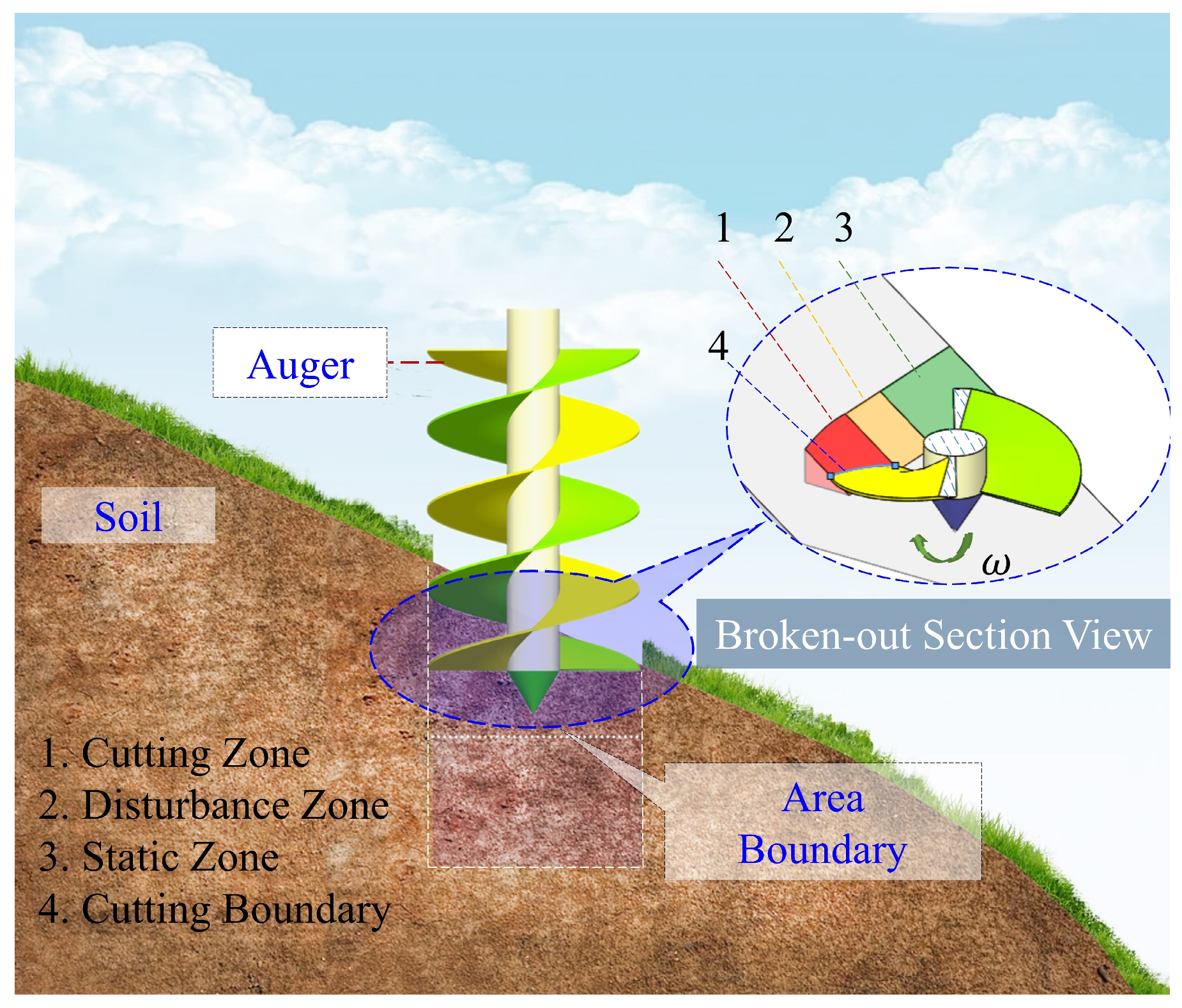
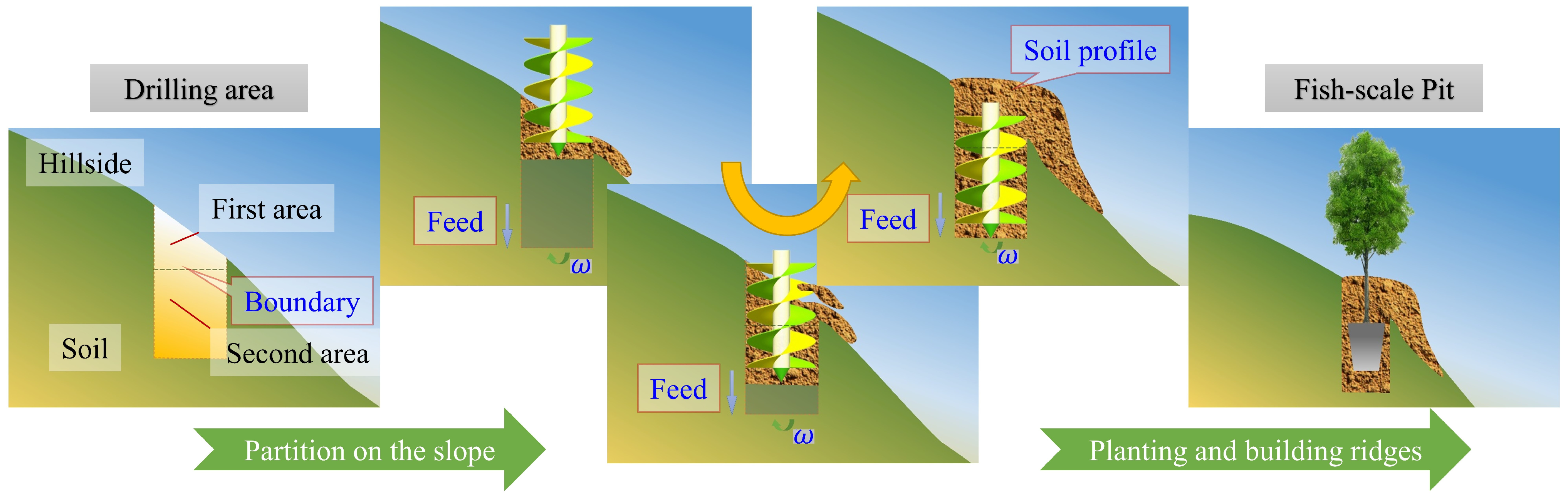
Figure 1 depicts a schematic representation of the interaction between the auger and the soil, providing a visual illustration of the contact between the two. According to the pre-experiment and tree planting technical requirements, the auger in the vertical plane forms an angle with the sloping ground to ensure the verticality of the pit body. Therefore, the working process of the auger can be divided into two parts, the first of which is slope cutting. The auger works in the first area, as shown in Figure 2, and the two spiral blades alternately dig the soil. The second process is deep digging. The auger works in the second area of Figure 2. The spiral blades are completely immersed in the soil. The continuous cutting pushes the soil flow continuously upward on the surface of the spiral blades. After the soil rises to the upper end of the spiral blades, it is thrown to the edge of the pit, as shown in Figure 2.
According to the pre-experiment, the soil involved at an instantaneous moment during digging can be divided into three areas before analysis, which were the cutting zone, the disturbance zone, and the static zone, as shown in Figure 1. The cutting area is where the soil is just cut off by the spiral blade and is away from its original position. The disturbance zone is where the soil has yet to be touched by the spiral blade, but it has been loosened due to the pressure disturbance from the lower end of the spiral blade and the soil in the cutting zone. The static zone refers to the area where the soil is still in its original position, not in contact with the spiral blade.
This study regards the soil in the cutting area as the mass point and establishes 3D Cartesian coordinates with the opposite direction of gravity as the Z axis. To simplify calculations, the XY plane (horizontal plane) is used as the plane where the circumferential speed of the spiral wing is located. Based on the theorem of velocity components and Figure 3a, Equation (1) can be obtained.
V a = V e + V r = V 1 + V 2 + V r
V 1 = ω r V 2 = S t = S ω 2 π
where V a is the absolute velocity. The absolute motion is the irregular spiral curve motion that flows to the pithead. The V a instantaneous direction is the direction of the motion tendency of point (p). V e is the transport velocity. The translational motion is a composite motion of the circular motion of the spiral blade and the downward feed motion of the auger. V r is the relative velocity. The relative motion is the movement of the soil particle ( p ) relative to the spiral surface. It moves upward along the surface of the spiral blade. The instantaneous direction is the tangent direction of the spiral surface at point p . The velocity of the soil particle ( p ) cannot be clearly expressed in a certain plane; therefore, the spatial system is needed to perform the calculation, as shown in Figure 3b. The absolute velocity ( V a ) can be decomposed into three component velocities, as shown in Equation (3).
V a x = V r cos β cos σ V a y = V r cos β sin σ ω r V a z = V r sin β S ω 2 π
where V 1 is the circumferential velocity of the soil particle ( p ) ; V 2 is the downward feed motion of the auger. S is the feed distance of one revolution of the auger. t is the time it takes for the auger to make one revolution. ω is the angular velocity of auger rotation. r is the radius of the auger. α is the angle between the transport velocity and the XY plane. β is the angle between the relative velocity and the XY plane. σ is the angle between the relative velocity and the XZ plane. Based on the description of the movement of the soil particle, it can be known that its movement trajectory is an irregular spiral curve. While the soil moves upward, it also rotates around the drill axis.
a a = a e t + a e n + a r t + a r n + a k
a e n = ω 2 r . a r n = v r 2 cos 2 β r a a = r ω v r cos β r 2
Figure 3c is the acceleration analysis diagram of the soil particles, and Equation (4) is formed based on the acceleration composition theorem, where a a is the absolute acceleration, and the direction and size are unknown. a e t is the tangential acceleration of the implicated motion. Because the dig velocity is fixed, the angular acceleration is 0. The value of a e t is 0. Similarly, the value of the relative velocity tangential acceleration ( a r t ) is 0. a e n is the normal acceleration of the implicated motion, and it points towards the center of rotation. a r n is the normal acceleration of the relative velocity, and it points towards the center of curvature of the spiral. a k is the Coriolis acceleration, and its direction is opposite to a r n . The value of various accelerations can be expressed as Equation (5). To describe the forces in the digging process more accurately, the particle ( p ) was regarded as a block in the analysis, as shown in Figure 3b. In this way, the particle ( p ) contains six surfaces, which can facilitate the analysis of the force in various directions. The dynamic analysis of the digging process can be expressed as Equation (6).
Σ F x = F t F s + f 1 f 2 cos β + f 3 f 4 = 0 Σ F y = N 4 N 3 N 2 sin β + F i = 0 Σ F Z = N 2 cos β G N 1 f 2 sin β = 0
where G is gravity, m is the weight of the soil, and g is the gravitational acceleration. N 1 is the pressure of the soil above the soil particle ( p ) . f 1 is the friction between the soil particle ( p ) and the soil above it. μ 1 is the friction coefficient between the different parts of the soil. N 2 is the supporting force of the soil particles on the surface of the spiral blade. f 2 is the friction between the soil particle ( p ) and the surface of the spiral blade. μ 2 is the friction coefficient between the soil and the surface of the spiral blade. N 3 is the pressure of the outer soil on the soil particle ( p ) . f 3 is the friction between the soil particle (p) and the outer soil. N 4 is the pressure of the inner soil on the soil particle ( p ) . f 4 is the friction between the soil particle ( p ) and the inner soil. F t is the propelling force of the soil in the back for particle ( p ) . F S is the resistance of the front soil towards particle ( p ) . F i is the inertial force of the soil particle ( p ) in movement. At a certain moment, F i appears as a centrifugal force, pointing towards the wall of the pit.
F i = m a a = m r ω V r cos β r 2
During the digging process, the primary function of the auger is to uplift the soil. Improving the efficiency of conveying soil is of paramount importance. Due to the presence of slopes, the distance of throwing soil that is ejected during digging will increase the workload for subsequent soil handling. Based on practical work experience and theoretical analysis, the controllable factors influencing the auger’s soil lifting capability primarily include the helix angle, rotational speed, and feed rate.
Conducting virtual experiments based on the orthogonal experimental method to evaluate the operational performance of the auger, the helix angle of the auger (A), the rotating speed of the auger (B), and the feeding speed (C) were selected as experimental factors, while the efficiency of conveying soil (R1) and the distance of throwing soil (R2) were set as experimental indicators. The efficiency of conveying soil refers to the quantity of soil ejected from the pit per unit of time. The distance of throwing soil refers to the distance between the farthest soil particles and the center of the rod plus the radius of the auger.

2.1.2. Scheme of Simulation Experiment

We explored the impact patterns of several factors on mechanical performance through orthogonal experiments, as follows: the helix angle of the auger (A), the rotating speed of the auger (B), and the feeding speed (C). Based on previous experimental studies, practical experience, and mechanism analyses, the appropriate levels of the experiment factors were established as indicated in Table 1. In the experiment, the slope angle was set at 35°. Augers with different helix angles were modeled using the SOILDWORKS (2009) software. The rotational speed and feed rate of the auger were configured in the EDEM (V2.6) software. Subsequently, the following sections will provide an overview of the simulation process for the virtual prototype.

2.2. Discrete Element Model

2.2.1. DEM Parameters and Virtual Soil Bin

DEM simulations were run using the EDEM software. The EDEM software was installed on a computer with an Intel (R) Core (TM) i7-8700 CPU @ 3.20 GHz with 32 GB of RAM. The virtual simulation method and process are illustrated in Figure 4.
In order to obtain the working process of the auger on the slope, this study established the tilt soil bin model in the EDEM software, as shown in Figure 4. The effect of the auger’s geometric features and operating parameters on its performance was evaluated by simulating the operation of the bit in a virtual soil bin using the DEM. The virtual soil bin was filled with spherical particles, with a nominal radius of 7 mm, assembled to mimic a soil bed. To make the particle assembly in the virtual soil bin behave as closely as possible to real soil, input parameters were calibrated and validated, as detailed in references [21,22]. The DEM particles were packed to a bulk voidage of 33.3705%, which was measured for soil in the field. The input parameters used to describe the DEM particle and tool material properties are given in Table 2. Table 2 also lists the input parameters used to define soil–soil and soil–tool interactions. In the ANALYST software interface (EDEM V2.6), the state and load of the auger and soil can be directly derived. We set different colors for the “Grid Bin Group” according to the depth in the digging area; the purpose was to track the soil movement trajectory in each area. In the interface of EDEM, post-processing, we added a “Clipping plane” to show how the auger in the pit interacts with the soil and gain a schematic diagram.

2.2.2. Contact Model

The contact model is an important basis for analyzing the adhesion between mechanical parts and soil particles. During digging operations, soil particles are subjected to a variety of compound forces [23,24]. The soil of afforestation land generally has a higher moisture content. Here, there was a cohesive and adhesive nature between the soil–soil and soil–tool. The cohesive force of the soil particles was mainly set according to their internal cohesion characteristics. A Hertz–Mindlin model with JKR and an additional model-bounding contact model was adopted as the primary contact model for both particle–particle and particle–tool interactions. This model was suitable for simulating materials that have obvious adhesion and agglomeration between particles due to static electricity, moisture, and other reasons. Table 3 presents the input parameters required for the contact models [25,26].

3. Discussion and Result

3.1. Experiment Results

The test results based on the orthogonal experimental design scheme are presented in Table 4. Based on the data samples in Table 4, data processing and analysis were conducted using the Box–Behnken module in the Design–Expert (8.0) software. To investigate the significance of each influencing factor and their interaction effects on evaluation indicators, the variance (ANOVA) analysis of the test results is shown in Table 5 and Table 6. According to the significance values (p) of the lack of fitting in the regression models of the objective functions (R1 and R2) in Table 5 and Table 6, PL1 = 0.1444 > 0.05 and PL2 = 0.1362 > 0.05 (both were not significant), indicating that no loss factor existed in the regression analysis, and the regression model exhibited a high fitting degree.
According to the ANOVA, the significance values (p) of each influencing factor in the test could be determined. For evaluation index R1, factors A, B, and C had extremely significant influences, while factors AB and BC had a significant influence. For evaluation index R2, factors A and B had extremely significant influences. Within the level range of the selected factors, according to the F value of each factor, as shown in Table 5 and Table 6, the weight of the factors affecting the efficiency of conveying soil is B > A > C. The weight of the factors affecting the distance of throwing soil is B > A > C.
In addition, there are interactions between the helix angle of the auger and the rotating speed of the auger, as well as between the feeding speed and rotating speed of the auger, on the efficiency of conveying soil (R1). The fitting coefficient of the efficiency of conveying soil is R2 = 0.9092. The p-value of the model for the efficiency of conveying soil is <0.1. The fitting coefficient of the distance of throwing soil is R2 = 0.9399. The p-value of the model for the distance of throwing soil is <0.1. It is indicated that the response surfaces of the two models established have good consistency and predictability for the experimental results. To express the interactive influence of each factor on the efficiency of conveying soil (R1), another factor was set to level 0, while the other two underwent an interaction effect analysis to study their influence on evaluation index R1, and the corresponding response surfaces were generated, as illustrated in Figure 5.
As can be seen in Figure 5a, when the rotating speed of the auger was fixed, the efficiency of conveying soil decreased with the increase in the helix angle. When the helix angle of the auger was fixed, the efficiency of conveying soil continued to increase with the increase in the rotation speed. When the rotating speed of the auger was fixed, the efficiency of conveying soil increased with the increase in the feeding speed; see Figure 5b. The following analysis will combine the dynamic analysis results of soil–auger generated using the EDEM software to elucidate the mechanisms that the experimental conclusions and data failed to capture.

3.2. The Impact of the Auger on Soil Disturbance

Loose soil is often analyzed as a fluid, like air and water. But in fact, its interaction force with machinery is several orders of magnitude larger than that of water and air. In addition, the form of force and the law of transformation are also different. The role of soil is not invariable in different positions and directions [27]. The main movements of the auger are rotary movement and longitudinal feed movement. The soil movement trend can be analyzed from Figure 6. Guided and cut by the spiral blades, the soil moves upward. On the low-altitude side, after losing the function of the pit wall, it slides down along the spiral blades. On the other hand, there is a movement trend in which the soil in the disturbance zone loosens. Based on a theoretical analysis, the rotation direction of the spiral blade is opposite to the relative movement direction of the soil particle (p). The isolated soil particle (p) has a downward trend on the surface of the spiral blade. When the soil moves upward on the surface, it overcomes gravity and surface friction on the spiral blades, gradually reducing its absolute velocity. Therefore, the frictional force and the component force of the support force on the surface of the spiral blade in the horizontal plane are important resistances in soil lifting. At the same time, the vertical component of the supporting force on the spiral blade surface is the main force that drives the soil particle (p) up. In short, the surface of the spiral blades promotes the longitudinal movement of the soil and retards the lateral movement. In terms of the shape of the spiral blade, the smaller the spiral angle within the allowable range, the better the soil lifting.
In terms of the feed movement of the auger, its main function is to obtain the cutting distance at the end of the auger to deepen the pit, as shown in Figure 7. As analyzed in combination with Equation (3), the feed movement determines the longitudinal movement speed of the soil and the thickness of the cut soil. If the soil is thicker, the soil block will gain a greater upward momentum ( m v ) and a greater centrifugal force ( F i ) . But soil that is too thick will lead to greater resistance, such as G ,   F s ,   N 2   sin β ,   f 2 . Due to the limited space of the blades, blockage is more likely to appear when the kinetic energy decreases. According to the analysis in Figure 7, the expression formula of the V e can be deduced as Equation (8). During the initial stages of a single digging, the kinetic energy of soil particles increases with higher feed speeds. However, in the later stages of digging, as the feed speed continues to increase, there is a larger volume of soil inside the pit per unit of time. Excessive resistance results in soil sliding back into the pit. Furthermore, this leads to the inadequate pushing of subsequent soil, causing soil to fill back in from the higher-altitude side. Taken together, these factors contribute to a decrease in the efficiency of conveying soil with increasing feed speeds. It is important to balance the velocity of rotation and the feed. When the rotation velocity is higher than the feed, the angle (α) decreases, and the cut soil becomes less thick. Then, the subsequent soil supply becomes insufficient, which will affect the soil uplifting. When the rotation velocity is much smaller than the feed, the angle (α) increases, which causes the soil thickness per unit of time to be much smaller than the feed distance. This will lead to stress concentration at the end of the auger that can easily damage the spiral blades. In summary, the closer the penetrating angle is to the helix angle, the better. As for the soil on the spiral blade, the feed motion propels the soil particle (p), which tends to leave the surface of the spiral blade, changing N2 and N1 in Equation (6). Therefore, excessive fluctuations in the feed velocity will disturb soil flow and affect soil lifting. Hence, it is particularly important to design a constant-velocity automatic feed-and-return device for digging.
V e = S ω 2 π tan α = ω r cos α S = 2 π r sin α
To validate the motion law depicted in the pictorial diagram, the load applied to the auger was exported to the software, as shown in Figure 8. The tangential force of contact exhibits significant fluctuations initially, followed by a trend towards stability. This phenomenon is attributed to the alternating contact between the auger and the soil during the slope-cutting process. As the feed distance increases, the torque and force experienced by the auger continue to increase. The rate of change decreases during the deep excavation process. The main reason is that the quality of the soil on the surface of the spiral blades continues to increase. However, due to the disappearance of the slope, the soil mass gradually stabilizes. The torque and force fluctuations observed in the auger can be attributed to two main factors. Firstly, the intermittent occurrence of clogging phenomena leads to random variations in torque and force. Secondly, an imbalance between the soil discharge and supply on the surface of the spiral blade also contributes to these fluctuations. This corresponds to the conclusions drawn from the theoretical analysis.

3.3. The Effect of the Interaction between Soils on Its Uplifting

The influence of soil characteristics on the performance of machinery cannot be ignored [28,29]. The interaction between soils in the digging area was analyzed according to Equation (6). As shown in Figure 9a,b, the kinetic energy of the soil is affected by the disturbance of the spiral blade. By analyzing the color changes, it can be observed that the kinetic energy of the soil decreases along the spiral blades as it moves upward. The reason is the soil particle ( p ) is in the middle, the front soil hinders its movement, while the subsequent soil promotes its movement. As shown in Figure 6b and Figure 9b,c, the soil at the edges of the blades has higher kinetic energy and moves outward from the pit first. Due to the action of centrifugal force, there is a tendency for the soil to move toward the edges of the helical blades. The amount of soil at the pit wall gradually increases. On the one hand, increasing the pressure between the soil and the helical blade surface contributes to the upward guidance of the helical blade surface. On the other hand, since the pit wall is relatively stationary, it hinders the downward sliding of the soil. However, with time, soil that does not move inward promptly can cause blockages. In contrast, the soil on the outer side, moving smoothly, is more conducive to upward movement.
In summary, the main challenges of soil lifting on the surface of the spiral blade are the friction on the surface, the inconsistency of the velocity between different parts of soil in the same area, and the resistance caused by the velocity attenuation of the front soil. The favorable factors for soil lifting are the continuous driving force of the subsequent soil and the guiding effect of the surface of the spiral blade. The main function of the outer and upper soil and the pit wall is to prevent the soil from sliding down the surface of the spiral blade so that the soil is relatively static and moves upward along the surface of the spiral blade in terms of absolute movement.

3.4. The Formation of the Fish-Scale Pit on the Slope

Due to the influence of the slope, the two spiral blades that feed in the vertical direction alternately cut the soil in the first zone (soil on the high-altitude side). Then, the soil moves uplift along the surface of the spiral blades. The soil in this area continues to be tracked. When the lower end of a spiral blade leaves the soil, turns to the low altitude area, and disposes of the obstruction of the pit wall, the soil will be thrown to the outside or slide down along the surface of the spiral blade, as shown in Figure 6a,b. According to the analysis of centrifugal force (Equation (7)), when it comes to augers of the same specification, the throwing radius is mainly determined by the angular velocity of the auger. In the case of a lower rotation speed, when the centrifugal force cannot overcome the frictional force between the soil and the spiral blade, the soil cannot be thrown away from the spiral blade [30]. Because of discontinuous digging, when the soil reaches the lower-altitude side, it loses the subsequent soil thrust and the outer soil pressure at the same time. Under the action of gravity, the soil will slide out along the spiral blades and accumulate on the low-altitude side. This finding, combined with the pre-experiment results, shows that when the velocity is too fast, due to the existence of the slope, the radius of the throwing soil will be larger than the plain regions. It will also cause the soil to rebound and roll down the slope, as shown in Figure 6b. An excessive soil-throwing range is not conducive to the back-filling of the original soil, and the power consumption will also increase.
One of the differences between digging operations on slopes and plain areas is the distribution of soil. In a reasonable combination of factors such as the rotation speed and helix angle, the best effect is to ensure that the amount of soil is large enough and that the soil is gathered in the pit. As the digging deepens, a horizontal soil-gathering peak will be formed at the mouth of the pit, as shown in Figure 6c. Currently, the shape of the pit wall is relatively regular. The soil will be discharged evenly around the pit. The soil will slide down along the soil-gathering peak slope to the low-altitude area instead of falling back into the pit. In this way, a fan-shaped soil collection peak forms on the slope. With some minor adjustments, it can be built into a fish-scale pit, as shown in Figure 2.
When using earth augers for the mechanized construction of fish-scale pits, the presence of a slope is advantageous for the formation of fan-shaped soil mounds. It reduces the workload of soil preparation on the ground. At the same time, it ensures the condition of the original soil, which is beneficial for the development of tree roots. It is important to note that excessive soil-throwing distances can result in an increased workload for soil covering after planting. Therefore, based on the results of the orthogonal experiment, the optimization of operational parameters such as the helix angle, drill bit speed, and feed rate are needed for different slope angles in subsequent work.

3.5. Prototype Fabrication and Field Testing

In order to test the operational performance of the suspended earth auger on the spot, in April 2023, a forest experiment was carried out at the Wuqi Forest Farm in Shanxi Province, as shown in Figure 10. The experimental area of the Wuqi Forest Farm is an arid mountainous area that is full of ravines with serious soil erosion. The slope is steep and short with frequent slope angle variation. Sparse grass and shrubs can be seen on the surface of the soil, and the soil is firm.
The digging experiment in the forest region was divided into deep digging in plain and slope regions. The diameter of the auger was 400 mm, the digging depth was 600 mm, the auger speed was 50 r/min, the auger helix angle was 20°, and the maximum angle of the slope was 35°. Comparing the actual and simulated results (such as Figure 6), it can be observed that the disturbance trajectory of the soil particles and the distribution shape of the soil on the slope were similar. The error rates for the actual and simulated values of the efficiency of conveying soil and the distance of throwing soil on plain terrain and slopes were 12.7% and 8.2%, and 8.6% and 15.7%, respectively. To measure the amount of soil discharged from the pit in the field experiment, we weighed the soil and then converted it proportionally, based on the weight of a single soil particle. The data were collected from pits where the manual operation of the auger was more up to standard. Each data point was measured six times and averaged, as shown in Table 7. The operating performance of the machinery was evaluated through a comparison with the industrial standards [31]. The field experiment proved that all indexes of the designed earth auger are within the qualification requirements. The auger can also build fish-scale pit-type soil peaks built on slopes, as shown in Figure 10b.

4. Conclusions

Ultimately, this research furnishes a theoretical basis for the innovative exploration, development, and optimized design of earth augers in hilly regions. A summary of the main conclusions is as follows:
(1)
The weight of the factors affecting the efficiency of conveying soil is in the following order: the rotating speed of the auger > the helix angle of the auger > the feeding speed. The weight of the factors affecting the distance of throwing soil is in the following order: the rotating speed of auger > the helix angle of auger > the feeding speed.
(2)
The main challenges of soil lifting on the surface of the spiral blade are the friction on the surface, the inconsistency of the velocity between different parts of soil in the same area, and the resistance caused by the velocity attenuation of the front soil. The favorable factors for soil lifting are the continuous driving force of the subsequent soil and the guiding effect of the surface of the spiral blade. The main function of the outer and upper soil and the pit wall is to prevent the soil from sliding down the surface of the spiral blade so that the soil is relatively static and moves upward along the surface of the spiral blade in terms of absolute movement.
(3)
Further work is needed to optimize the motion and structural parameters of hole-digging machines based on the fish-scale pit construction method. To ensure the smooth uplift of the soil, it is particularly important to design a constant-velocity automatic feed and return device for digging.
(4)
The error rates for the actual and simulated values of the efficiency of conveying soil and the distance of throwing soil on plain terrain and slopes were 12.7% and 8.2%, and 8.6% and 15.7%, respectively. The discrete element method effectively explores the interaction mechanisms between augers and soil.

Author Contributions

Conceptualization, G.W. and W.Z.; methodology, G.W. and W.Z.; software, X.D., W.Z. and M.C.; validation, M.J. and W.Z.; formal analysis, G.W.; investigation, M.J. and X.D.; resources, W.Z. and H.M.; data curation, G.W. and H.M.; writing—original draft preparation, G.W.; writing—review and editing, G.W., W.Z. and M.C.; supervision, W.Z. and H.M.; funding acquisition, W.Z. All authors have read and agreed to the published version of the manuscript.

Funding

This work was supported by a program of the National Natural Science Foundation of China (CN) (grant no. 31670721), the China Green Foundation (grant no. [2021]7), and the Key R&D and Transformation Program of Qinghai Province—Special Project of Transformation of Scientific and Technological Achievements (grant no. 2022-NK-128).

Data Availability Statement

The data sets generated during and/or analyzed during the current study are available from the corresponding author upon request.

Conflicts of Interest

The authors declare no conflicts of interest.

References

  1. Franca, J.S.; Reichert, J.M.; Holthusen, D.; Rodrigues, M.F.; de Araujo, E.F. Subsoiling and mechanical hole-drilling tillage effects on soil physical properties and initial growth of eucalyptus after eucalyptus on steep lands. Soil Tillage Res. 2021, 207, 104860. [Google Scholar] [CrossRef]
  2. Yang, Z.; Chen, C.; Duan, J.; Yan, G.; Pan, X.; Yan, L.; Liu, J. Performance test of hand-held electric hole-digger for fertilization in orchard. Trans. Chin. Soc. Agric. Eng. Trans. CSAE 2013, 29, 25–31. [Google Scholar] [CrossRef]
  3. Keller, T.; Sandin, M.; Colombi, T.; Horn, R.; Or, D. Historical increase in agricultural machinery weights enhanced soil stress levels and adversely affected soil functioning. Soil Tillage Res. 2019, 194, 104293. [Google Scholar] [CrossRef]
  4. Liang, J.; Liu, Y.; Wang, Z.; Fan, C. The Structure Design on Tilting Fish-scale Pits Plough. J. Agric. Mech. Res. 2015, 37, 91–94. [Google Scholar] [CrossRef]
  5. Chen, J.; Xiao, H.; Li, Z.; Liu, C.; Ning, K.; Tang, C. How effective are soil and water conservation measures (SWCMs) in reducing soil and water losses in the red soil hilly region of China? A meta-analysis of field plot data. Sci. Total Environ. 2020, 735, 139517. [Google Scholar] [CrossRef]
  6. Lian, S.; Li, Z. Theoretical analysis of soil-raising on the drill bit of a digger. Grain Oil Process. Food Mach. 1975, 12, 57+63–66. [Google Scholar]
  7. Zhou, F.; Zhao, R.; Qin, S. Research on relevant main parameters of portable digging machine. For. Mach. 1986, 5, 7–9+44. [Google Scholar]
  8. Guisheng, G.; Mengxiang, G.; Kangquan, G. Study of screw auger parameters of mounted hole digger on the basis of MATLAB. J. Northwest Agric. For. Univ. Nat. Sci. Ed. 2003, 3, 179–182. [Google Scholar] [CrossRef]
  9. Wu, L.; Guo, K.; Man, D. Design and model selection of hydraulic systems for a self-propelled hole digger. For. Mach. Woodwork. Equip. 2016, 44, 24–28. [Google Scholar] [CrossRef]
  10. Su, N.; Guo, K.; Man, D.; Zhu, J.; Wang, W. Design and Test of 3WG-400 Vehicle-mounted Digging Machine. For. Mach. Woodwork. Equip. 2018, 46, 12–15. [Google Scholar] [CrossRef]
  11. Zong, W.; Wang, J.; Huang, X.; Yu, D.; Zhao, Y.; Sean, G. Development of a mobile powered hole digger for orchard tree cultivation using a slider-crank feed mechanism. Int. J. Agric. Biol. Eng. 2016, 9, 48–56. [Google Scholar] [CrossRef]
  12. Ma, L.; Wang, J.; Zong, W.; Huang, X.; Feng, J. Design and experiment of automatic feed mechanism of the portable digging machine. Trans. Chin. Soc. Agric. Eng. 2017, 33, 25–31. [Google Scholar] [CrossRef]
  13. Ma, L.; Liang, Y.; Huang, X.; Zong, W.; Zhan, G. Development of automatic lifting digging machine based on three-star gear reversing principle. Trans. Chin. Soc. Agric. Eng. 2018, 34, 46–51. [Google Scholar] [CrossRef]
  14. Zhang, Y. Structural Design and Analysis of Four-Legged Digging Robot. Master’s Thesis, Beijing Forestry University, Beijing, China, 2018. [Google Scholar]
  15. Du, D.; Ma, Y.; Guo, X.; Lu, H. Research on a forestation hole digging robot. In Proceedings of the 2010 International Conference on Intelligent Computation Technology and Automation, Changsha, China, 11–12 May 2010; pp. 1073–1076. [Google Scholar] [CrossRef]
  16. Fang, Q. Application of Excavator in Forestry Development. Agric. Sci. Technol. Equip. 2020, 02, 56–58. [Google Scholar] [CrossRef]
  17. Engin, S.; Altintas, Y. Mechanics and dynamics of general milling cutters Part I: Helical end mills. Int. J. Mach. Tools Manuf. 2005, 45, 967–977. [Google Scholar] [CrossRef]
  18. Karthick, R.; Gopalakrishnan, S. Design and fabrication of multipurpose PIT digger machine. Materials machine. Mater. Today Proc. Today Proc. 2020, 21, 449–451. [Google Scholar] [CrossRef]
  19. Xie, Y.; Ferng, Y.; Miao, J.; Ren, J.; Zhang, X. Numerical and experimental study on optimization of paddy field blade used in initial mud-cutting process. Comput. Electron. Agric. 2020, 170, 105243. [Google Scholar] [CrossRef]
  20. Ucgul, M. Simulating Soil–Disc Plough Interaction Using Discrete Element Method–Multi-Body Dynamic Coupling. Agriculture 2023, 13, 305. [Google Scholar] [CrossRef]
  21. Aikins, K.A.; Barr, J.B.; Antille, D.L.; Ucgul, M.; Jensen, T.A.; Desbiolles, J.M. Analysis of effect of bentleg opener geometry on performance in cohesive soil using the discrete element method. Biosyst. Eng. 2021, 209, 106–124. [Google Scholar] [CrossRef]
  22. Sun, J.; Wang, Y.; Ma, Y.; Tong, J.; Zhang, Z. DEM simulation of bionic subsoilers (tillage depth > 40 cm) with drag reduction and lower soil disturbance characteristics. Adv. Eng. Softw. 2018, 119, 30–37. [Google Scholar] [CrossRef]
  23. Wang, J.; Tang, H.; Wang, J.; Huang, H.; Lin, N.; Zhao, Y. Numerical Analysis and Performance Optimization Experiment on Hanging Unilateral Ridger for Paddy Field. Trans. Chin. Soc. Agric. Mach. 2017, 48, 72–80. [Google Scholar] [CrossRef]
  24. Wang, Y. Study on Mining Mechanism of Panax Notoginseng Based on Discrete Element Method. Master’s Thesis, Kunming University of Science and Technology, Kunming, China, 2021. [Google Scholar]
  25. Tong, Z. Design and Experiment of Compound Cutting Parts of Tobacco Hilling Machine. Master’s Thesis, Henan Agricultural University, Zhengzhou, China, 2020. [Google Scholar]
  26. Li, J.; Tong, J.; Hu, B.; Wang, H.B.; Mao, C.Y.; Ma, Y.H. Calibration of parameters of interaction between clayey black soil with different moisture content and soil-engaging component in northeast China. Trans. Chin. Soc. Agric. Eng. 2019, 35, 130–140. [Google Scholar] [CrossRef]
  27. Naclerio, N.D.; Karsai, A.; Murray-Cooper, M.; Ozkan-Aydin, Y.; Aydin, E.; Goldman, D.I.; Hawkes, E.W. Controlling subterranean forces enables a fast, steerable, burrowing soft robot. Sci. Robot. 2021, 6, 2922. [Google Scholar] [CrossRef] [PubMed]
  28. Karpman, E.; Kövecses, J.; Holz, D.; Skonieczny, K. 2020. Discrete element modelling for wheel-soil inter-action and the analysis of the effect of gravity. J. Terramech. 2020, 91, 139–153. [Google Scholar] [CrossRef]
  29. Makange, N.R.; Ji, C.; Torotwa, I. Prediction of cutting forces and soil behavior with discrete element simulation. Comput. Electron. Agric. 2020, 179, 105848. [Google Scholar] [CrossRef]
  30. Zhuo, F. Digging Machine; China Forestry Publishing House: Beijing, China, 1989; pp. 56–121. [Google Scholar]
  31. LY/T 1490-2006; Mounted Planting Auger. Standards Press of China: Beijing, China, 2006.
Figure 1. Schematic representation of the interaction between the auger and the soil.
Forests 15 00190 g001
Figure 2. Schematic diagram of digging operation process in hilly regions.
Forests 15 00190 g002
Figure 3. Kinematics and dynamic characteristics analysis of the auger during soil cutting on the slope. (a) Velocity analysis of soil particles. (b) Force analysis of soil particles. (c) Acceleration analysis of soil particles.
Forests 15 00190 g003
Figure 4. The process of virtual simulation using DEM.
Forests 15 00190 g004
Figure 5. Three-dimensional response diagram effect of evaluation indices. (a) Effect of interaction between A and B on the efficiency of conveying soil. (b) Effect of interaction between B and C on the efficiency of conveying soil.
Forests 15 00190 g005
Figure 6. Simulation diagrams of the digging process.
Forests 15 00190 g006
Figure 7. Schematic diagram of soil cutting at the end of the auger.
Forests 15 00190 g007
Figure 8. Graphs illustrating simulation data. (a) The tangential force diagram of contact between auger and soil during slope operation. (b) The force diagram of the spiral blades. (c) The torque diagram of the auger.
Forests 15 00190 g008
Figure 9. The soil kinetic energy based on effects of the disturbance of spiral blades. (a) Soil kinetic energy nephogram at the edge of helical blades. (b) Soil kinetic energy nephogram inside helical blades. (c) Normal force nephogram map of soil–tool contact.
Forests 15 00190 g009
Figure 10. Operation diagram at the experiment site. (a) Effect diagram of plain ground digging. (b) Effect diagram of slope digging.
Forests 15 00190 g010
Table 1. Factors and levels of the virtual orthogonal experiment.
LevelExperiment Factors
A (°)B (r/min)C (m/s)
110300.04
016750.07
−1221200.1
Table 2. Material properties of soil and tool.
ParameterSoilTool
Diameter particle (mm)7-
Contact radius (mm)8.5-
Particle density (kg/m3)13507860
Shear modulus (Pa)1 × 1067.9 × 1010
Poisson’s ratio0.30.3
Coefficient of restitution of soil0.20.26
Coefficient of static friction of soil0.540.5
Coefficient of rolling friction of soil0.20.04
Table 3. Parameters of contact models.
ParameterUnitValue
Normal Stiffness per unit areaN·m−22.1 × 10⁸
Shear Stiffness per unit area N·m−28 × 107
Critical Normal StressPa1.5 × 106
Critical Shear StressPa8 × 105
Bonded Disk Radiusmm2.5
Surface energy of soil–soil J·m−37.46
Surface energy of soil–toolJ·m−35.5
Table 4. Experiment schemes and results.
No.A (°)B (r/min)C (m/s)R1 (Num./s)R2 (mm)
116750.0718001994
2161200.0419212190
310300.0717501450
410750.0418851710
522750.0415862098
616750.0717801988
716750.0718702085
810750.119881770
916300.0414101680
1022300.0713201700
1116300.119001570
12161200.120532230
1316750.0718222015
14221200.0719362350
1516750.0717361949
16101200.0719301970
1722750.116772110
Table 5. ANOVA of model for R1.
Source of VarianceSum of SquaresdfMean SquareF-Valuep-ValueSignificant
Model5.629 × 105693,821.2516.690.0001***
A1.336 × 10511.336 × 10523.770.0006***
B2.665 × 10512.665 × 10547.40<0.0001***
C83,232.00183,232.0014.810.0032***
AB47,524.00147,524.008.450.0156**
AC36.00136.000.00640.9378Not significant
BC32,041.00132,041.005.700.0381**
Residual56,216.26105621.63
Lack of Fit46,349.0667724.843.130.1444Not significant
Pure Error9867.2042466.80
Cor Total6.191 × 10516
*** Means extremely significant (p < 0.01); ** means very significant (0.01 ≤ p <0.05); “df” means degree of freedom.
Table 6. ANOVA of model for R2.
Source of VarianceSum of SquaresdfMean SquareF-Valuep-ValueSignificant
Model9.254 × 10561.542 × 10526.07<0.0001***
A2.305 × 10512.305 × 10538.97<0.0001***
B6.845 × 10516.845 × 105115.70<0.0001***
C0.500010.50000.00010.9928Not significant
AB4225.0014225.000.71420.4178Not significant
AC576.001576.000.09740.7614Not significant
BC5625.0015625.000.95090.3525Not significant
Residual59,156.76105915.68
Lack of Fit49,117.9668186.333.260.1362Not significant
Pure Error10,038.8042509.70
Cor Total9.846 × 10516
*** Means extremely significant (p < 0.01); “df” means degree of freedom.
Table 7. Results and comparison of validation test.
TerrainR1 (Num./s)R2 (mm)
Simulation ValueText ValueRelative Error (%)Simulation ValueText ValueRelative Error (%)
Plain1100126012.7%7808508.2%
Slope148016208.6%2350203015.7%
Disclaimer/Publisher’s Note: The statements, opinions and data contained in all publications are solely those of the individual author(s) and contributor(s) and not of MDPI and/or the editor(s). MDPI and/or the editor(s) disclaim responsibility for any injury to people or property resulting from any ideas, methods, instructions or products referred to in the content.

