Article

Numerical Simulation of Ablative Damage in Gas-Assisted Laser Processing of Wood

1
College of Engineering, Heilongjiang Bayi Agricultural University, Daqing 163000, China
2
College of Mechanical and Electrical Engineering, Northeast Forestry University, Harbin 150040, China
*
Author to whom correspondence should be addressed.
Forests 2024, 15(8), 1296; https://doi.org/10.3390/f15081296
Submission received: 19 June 2024 / Revised: 22 July 2024 / Accepted: 23 July 2024 / Published: 25 July 2024
(This article belongs to the Section Wood Science and Forest Products)

Abstract

:
To reduce defects in wood laser processing, this study establishes a multi-field coupling model that reflects the coupling relationship between laser energy, auxiliary gas, and slit quality. It reveals the temperature field distribution and heat transfer during this process at a macroscopic level. Using the COMSOL Multiphysics 5.6 software to simulate laser processing with or without helium gas assistance, we show that helium-assisted laser processing positively affects the quality of wood processing. We further researched the influence of different laser powers and spot radii on ablation damage volume and gasification volume, and the results indicate that the adopted model effectively simulates the influence of laser power and auxiliary gas on laser cutting ability, accurately reflecting the impact of different process parameters on cutting depth and kerf width. The accuracy and effectiveness of this model were validated through comparison with experimental data. This research enhances process reliability and economic benefits through numerical simulation and prediction, expands theoretical research and engineering applications in the laser processing field, and optimizes and innovates wood processing technology. It provides a promising method for enhancing the added value of wood products and efficiently using wood resources.

1. Introduction

Laser processing is an advanced manufacturing technology with exceptional flexibility and intelligence. It is characterized by high cutting precision, extensive degrees of freedom, and efficient adaptability [1]. The interaction between a high-energy density laser beam and materials enables the non-contact processing of complex components and efficient formations. Its autonomous control capabilities, safety features, and efficiency advantages have led to its development in the wood processing field [2,3]. However, due to material-related limitations, uneven heat diffusion during the cutting process results in an enlarged heat-affected zone and severe surface burn damage [4]. The recast layer and thermal damage generated during processing affect molding quality and reduce material machining accuracy and reliability [5].
To mitigate laser processing defects, some scholars have proposed integrating gas-assisted technology with laser processing. Using gas as the only substance in contact with the workpiece, its physical properties and flow characteristics can be used to protect the processing interface and achieve high-quality processing [6]. Laser processing can be divided into several types, based on whether auxiliary gas participates in combustion [7]. One type uses oxygen to cause oxidation combustion and provide additional heat to improve processing efficiency. The other type is not involved in laser processing directly; instead, it uses nitrogen or air flow for purging and cooling purposes [8,9]. Laser cutting can be effectively regulated through the synergistic effect of laser energy and auxiliary gas [10,11,12].
In recent years, scholars have preliminarily explored gas-assisted laser processing for wood. Sulaiman et al. studied the effect of gas pressure on the quality of laser cutting in laminates, using higher pressure levels to promote nitrogen–air mixing and reduce the oxygen concentration at the cutting section [13]. Hernández Castañeda et al. developed a hydrodynamic model to compare the effects of different gasses at different pressures on slit quality [14]. Nukman et al. investigated the impact of compressed air- and nitrogen-assisted laser processing on wood, focusing on the material removal rate and cauterization degree. They discussed the minimum combustion effects and surface degradation that could be achieved under optimal cutting conditions [15]. Yilbas et al. examined the impact of the jet and heat conduction process of gas jets sprayed onto a solid surface with coaxial nozzles, establishing a low-Reynolds-number flow equation and analyzing temperature distribution changes within the substrate [16]. Preliminary progress has been made in research on gas-assisted laser processing for wood but, due to the photothermal conversion and energy transfer that occur in all processes, the transient evolution of heat conduction and ablation in the processing area is difficult to observe in real-time [17]. Additionally, the temperature field change caused by thermodynamic action during gas-assisted laser processing for wood and the influence of gas flow field disturbance on surface quality and the carbonization region have not been reported.
This study aims to enhance the carbonization and quality of wood surfaces. It establishes a basic model that reflects heat transfer between laser energy, auxiliary gas, and processed wood, explaining the macroscopic behavior of temperature field changes and ablation damage inside wood under gas-assisted laser processing. It demonstrates the oxygen disconnection, flame retardation, and carbonization-inhibiting effects of the auxiliary gas during this process. Our numerical simulation not only comprehensively considers the gas flow process and the thermal exchange between laser and wood, but also enables a coupling analysis of multiple physical fields. Compared with traditional wood processing that relies on experiments and experience, our method has more advantages and potential in predicting temperature field distribution, stress changes, and wood processing results.

2. Methodology

2.1. Control Equation

The heat transfer process in gas-assisted laser processing for wood adheres to the energy conservation principle. The control equation changes with the varying solid phase, liquid phase, or multiphase state of the substance [18,19]. When wood is irradiated by high-energy laser beams, the continuous action of the laser heat source forms an ablative region on the surface and transmits into its interior. The heat transfer process can be described by Fourier’s law of heat conduction [20]:
ρ C P T t + · ( k T ) = Q
where ρ is wood density (kg/m3), C P is the specific heat capacity of wood (J/kg·K), k is thermal diffusivity (W/(m·K)), and Q is the calorific value of the internal heat source (W/m3). In research on the temperature field of gas-assisted laser processing for wood, the heat transfer of the gas jet to the temperature field is mainly convection heat transfer [21], which is closely related to the gas flow field. The convection term can be expressed as
ρ C P u · T
where u is the gas flow rate (m/s). Therefore, Equation (1) can be rewritten as
ρ C P T t + ρ C P u · T + · ( k T ) = Q
The primary mechanism for material removal in gas-assisted laser processing for wood is high-temperature gasification. As wood does not have a liquid state, this study solely focused on the changes in physical properties when solid and gas phases are present [22,23,24]. Assuming that phase transition occurs within a temperature range of T p c T / 2 and T p c + T / 2 , the latent heat, L, is incorporated into the energy balance equation before the material reaches the phase transition temperature, T p c . When the temperature is lower than T p c T / 2 , θ = 1, no phase transition will occur, and when the temperature rises to T p c + T / 2 , θ = 0, complete gasification occurs. The thermodynamic relationship of specific enthalpy, H, can be expressed as follows:
H = θ H 1 + ( 1 θ ) H 2
C P = H + C L ( T ) = 1 ρ [ θ ρ 1 C P 1 + ( 1 θ ) ρ 2 C P 2 ] + L α T
where H 1 is the enthalpy of phase 1 before phase transition (KJ/mol), H 2 is the enthalpy of phase 2 after phase transition (KJ/mol), θ is a proportion of the pre-transition phase, and α T is a Dirac pulse. The latent heat distribution, C L , can be approximated as
C L ( T ) = L α T
Assuming that the total heat released per unit volume during the phase transition process coincides with the latent heat, we can obtain
T p c T / 2 T p c + T / 2 C L ( T ) d T = L T p c T / 2 T p c + T / 2 d α d T d T = L

2.2. Model Construction

The subject of this research is wood veneer with a specific thickness, so the heat loss in the depth direction during laser irradiation should not be ignored. Therefore, the heat source model should accurately describe the thermal behavior of laser energy along the effective radius direction and the energy attenuation trend along the thickness direction [25]. The rotating Gaussian body heat source model simulates the temperature field of gas-assisted laser processing for wood. The corresponding heat source equation is presented as follows [26]:
q ( x , y , z ) = 3 C s Q π H D ( 1 1 e 3 ) e x p 3 C s l o g ( H D z ) ( x 2 + y 2 )
C s = 3 R H 2
where H D is the heat source depth (mm), C s is the concentration coefficient of the heat source, and R H is the opening radius of the body heat source (mm).
Using the COMSOL Multiphysics 5.6 software for numerical simulation, the finite element model for gas-assisted laser processing for wood is shown in Figure 1. A porous medium heat transfer module under the heat transfer module branch was selected. Simultaneously, a fluid flow module and chemical transfer module were added. A 20 mm × 5 mm × 2.5 mm (length × width × height) cuboid model was constructed. The model did not move while the laser heat source moved along the x-axis. The distance between the nozzle and the workpiece was 1 mm. To ensure mass conservation and promote the better development of the auxiliary gas flow field, air areas were established on both the upper and lower surfaces of the workpiece as auxiliary gas outlets. Additionally, the gas flow area within the nozzle and the wood processing area was refined to enhance calculation accuracy.
During gas-assisted laser processing for wood, the problem is harder to solve owing to the complex interaction between multiphase flows. To achieve a convergent numerical solution in a finite element simulation, the following assumptions were made without affecting the accuracy of the results:
(1)
Wood is an isotropic homogeneous material with uniform heat transferred in all directions.
(2)
As a non-metallic material, wood has fewer free electrons for heat transfer, which is mainly accomplished through lattice vibration. The temperature change has a minimal effect on thermal conductivity; hence, variations in thermal conductivity with temperature are neglected, and the laser absorption rate of wood is assumed to remain constant.
(3)
The physical characteristic parameters of gas involved in laser processing are assumed to remain constant.
(4)
The influence of steam generated in laser energy distribution during processing is ignored.

2.3. Materials and Methods

The CO2 laser cutting machine (Jinan Baomei Numerical Control Technology Co., Ltd., Jinan, China) used in this experiment is shown in Figure 2; its wavelength was 10.6 µm, the rated power was 80 W, the maximum processing speed was 200 mm/s, the spot diameter was 0.1 mm, the pulse width was 20 ns, the pulse repetition frequency ranged from 1 kHz to 10 kHz, and the lens focal length was 63.5 mm. The influence of wood moisture content, density, and other factors in the laser absorption rate of wood was considered during gas-assisted laser processing. Cherry wood veneer was selected as the test substrate; the specifications were 120 mm × 80 mm × 2.5 mm (length × width × thickness), and the moisture content was 11%. Industrial helium with purity ≥ 99.999% was selected as the auxiliary gas. An Apreo scanning electron microscope (SEM) produced by Thermo Scientific (Waltham, MA, USA) was used to observe the microstructure of the slit surface resulting from gas-assisted laser processing. The landing energy of the SEM ranged from 20 eV to 30 keV, the bias voltage of the sample stage ranged from −4000 V to +600 V, the xy-axis travel range of the sample stage was 110 mm × 110 mm, and the tilt was within a range of −15° to +90°.
As the wood ablative process requires a high-energy laser beam to provide sufficient energy, slit formation is used as a chemical process. The changes in unit volume cause heat release and damage during the wood ablative process. The Arrhenius equation provides an evaluation method for the relationship between activation energy, temperature, and the chemical reaction rate in this chemical reaction [27,28]. Its expression is as follows:
a s t = ( 1 a s ) n A e E R g T k
where a s is the damage degree; A is the frequency factor; R g is the gas state quantity constant, the value being 8.31; E is the activation energy (KJ/mol); and T k is the absolute temperature (K).
Equation (10) shows that temperature was the main factor in determining the damage speed. During the wood laser ablation process, the damage was irreversible, and the damage level range was between 0 and 1. A value of 0 indicated no damage, and a value of 1 indicated the limit beyond which further destruction was not possible. If the value of a s was equal to 1, then 1 − a s would be equal to 0, indicating that the damage range had reached its maximum and would no longer change with increasing temperatures. If the value of a s was between 0 and 1, it implied that the wood could continue to be damaged with increasing time or temperatures.
To study the effect of process parameters on the temperature field and ablative damage of laser-processed wood, we fixed the sample to a workbench, and the laser beam entered the processing area through the feed system. The auxiliary gas was regulated and stabilized by a pressure-reducing valve; then, the gas entered the nozzle through a catheter and was sprayed onto the wood surface along with the laser beam. We simulated the effects of laser processing on wood ablation damage with and without gas assistance and analyzed the effects of different spot radii and laser powers on this damage. The process parameters are shown in Table 1.

3. Results and Discussion

3.1. Influence of Gas-Assisted Laser Processing on Wood Ablation Damage

To investigate the influence of gas-assisted laser processing on wood ablation damage, Scheme a in Table 1 was selected for parameter design. A comparison of the damage volume in the ablation process with and without gas assistance is shown in Figure 3. The high-energy laser beam irradiated onto the wood surface resulted in gasification and slit formation. Simultaneously, owing to the heat conduction effect, the area that did not reach the boiling point came into contact with air, and a combustion reaction occurred. The axial and radial extension of heat on the slit surface increased the incision size. The final incision size was the ablative damage volume formed by gas-assisted laser processing. The figure shows that the ablative damage volume generated without gas assistance was greater than the damage generated by helium-assisted laser processing. This was because an oxidative combustion reaction occurred between the wood and the air during the laser ablation process, increasing the incision size. The damage volume of the wood also increased. Helium is an inert gas, and it was sprayed onto the wood surface through a laser coaxial nozzle; owing to its physical characteristics, helium has difficulty reacting with air at high temperatures. Wood ablation mainly occurred through gasification, and no combustion reaction occurred after laser processing. Thus, the wood damage volume decreased.

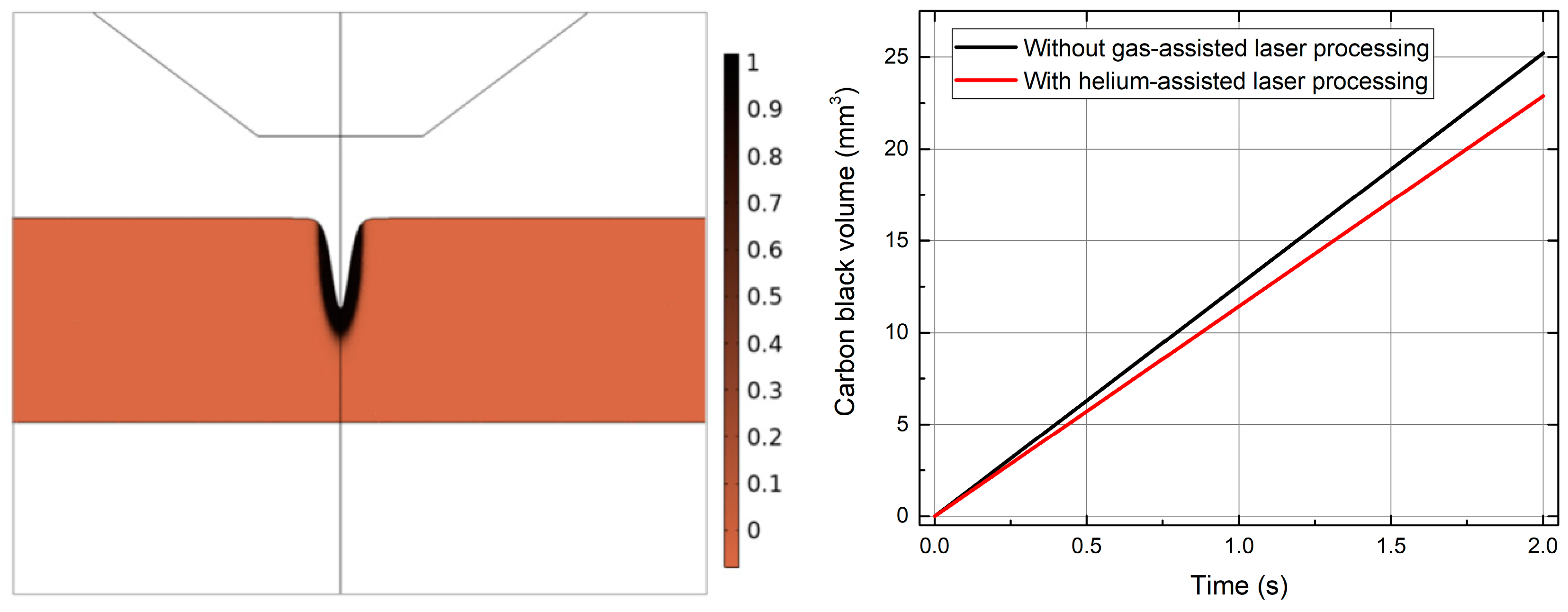
3.2. Influence of Gas-Assisted Laser Processing on Wood Carbon Black Volume

A carbon black volume comparison during laser processing with or without gas assistance is shown in Figure 4. The residual carbon black volume refers to the formation of a carbonization layer on the slit surface during wood laser ablation. The residual carbon black volume generated without gas-assisted laser processing was greater than that generated with helium-assisted laser processing. Due to the expanded heat-affected zone caused by heat transfer during the wood-burning process, many carbides adhered to the slit surface, resulting in a larger residual carbon black volume. Helium-assisted laser processing fundamentally prevented heat release through oxygen disconnection and flame-retardant mechanisms. Meanwhile, due to the cooling and purging effect of airflow, the temperature on the slit surface decreased, the heat-affected zone expansion was inhibited, and the residual carbon black volume decreased.
Helium is an inert gas that is not prone to chemical reactions, and can fundamentally prevent heat release through oxygen disconnection and flame-retardant effects. Our analysis shows that it can effectively reduce the surface temperature and ablative damage when processing wood.

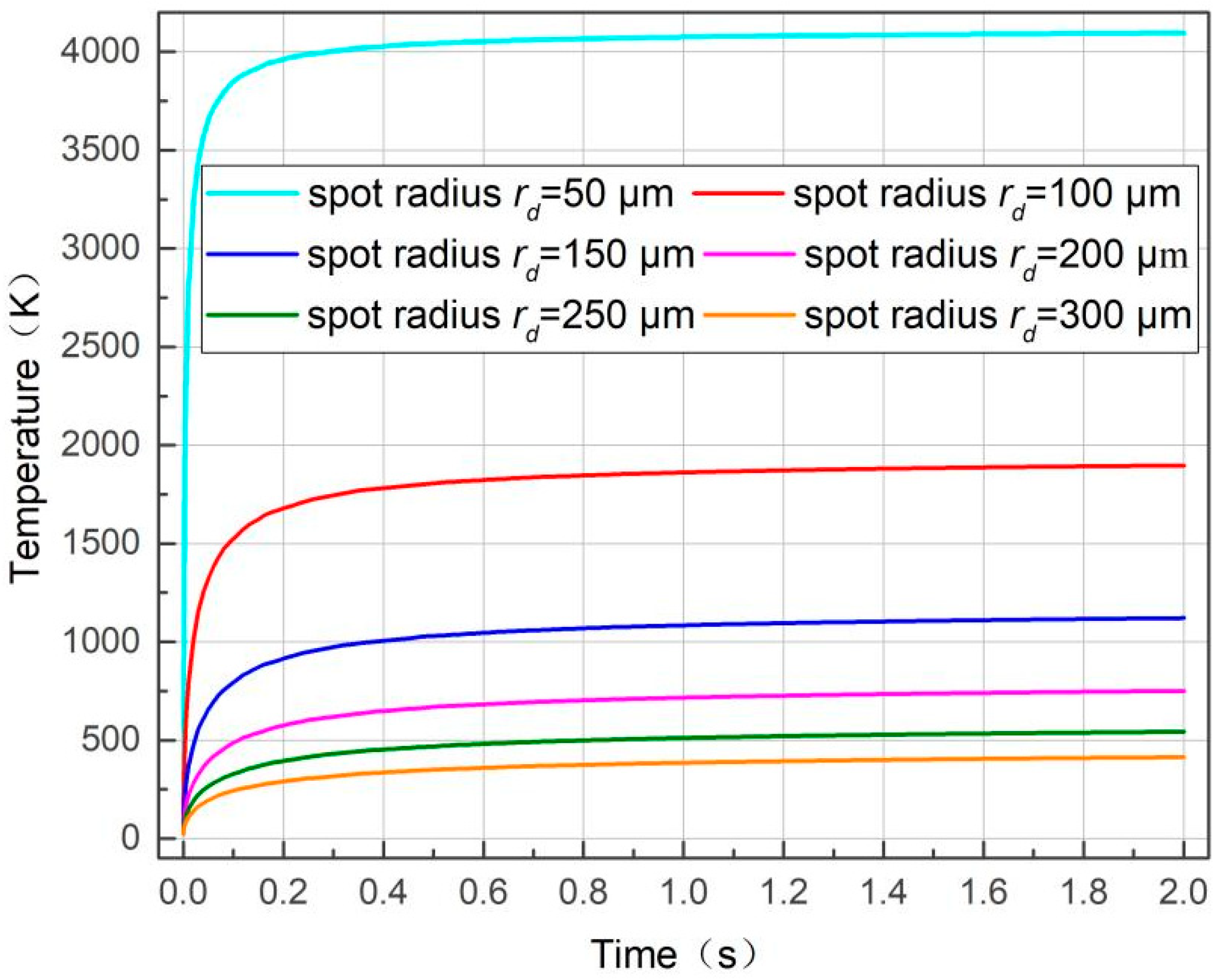
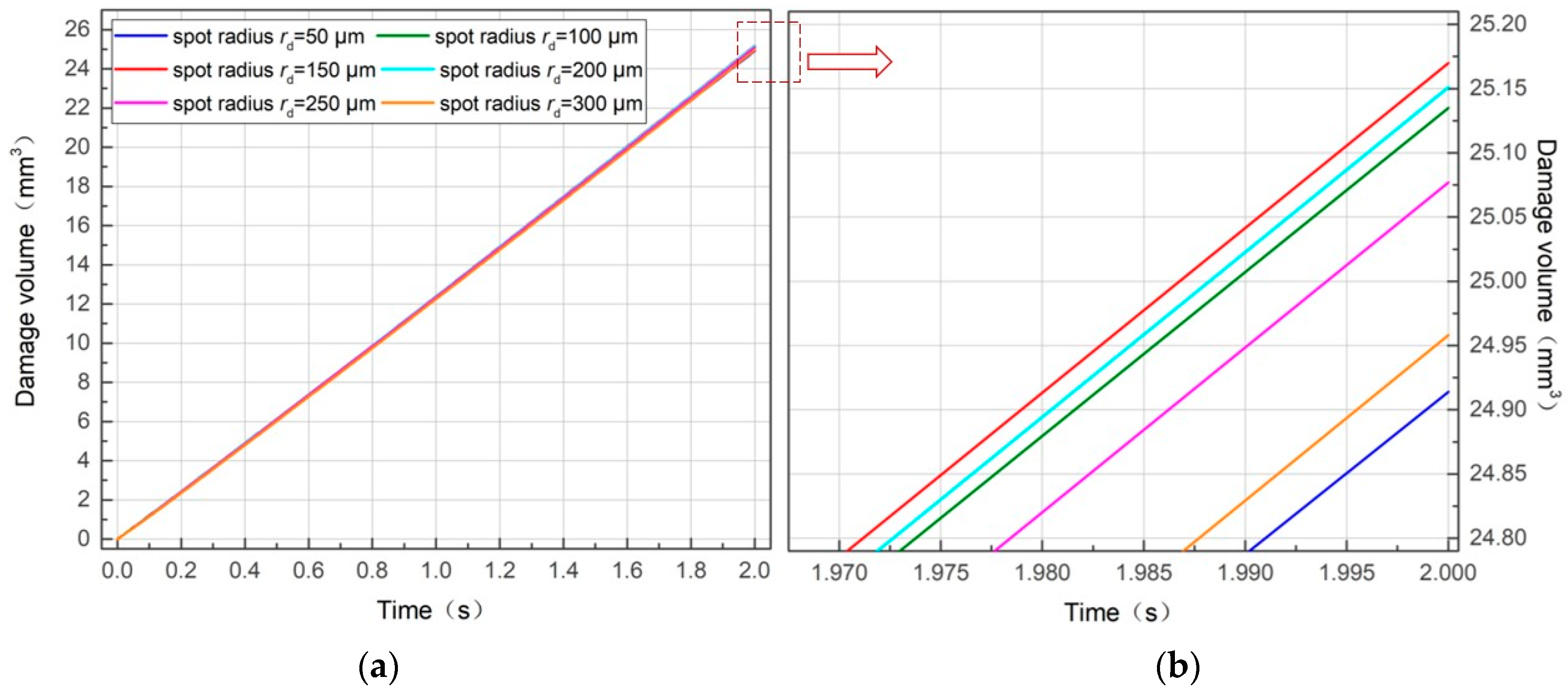
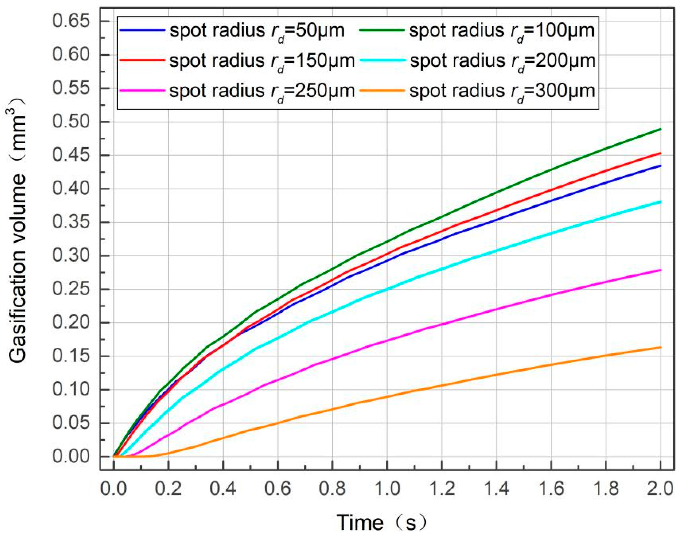
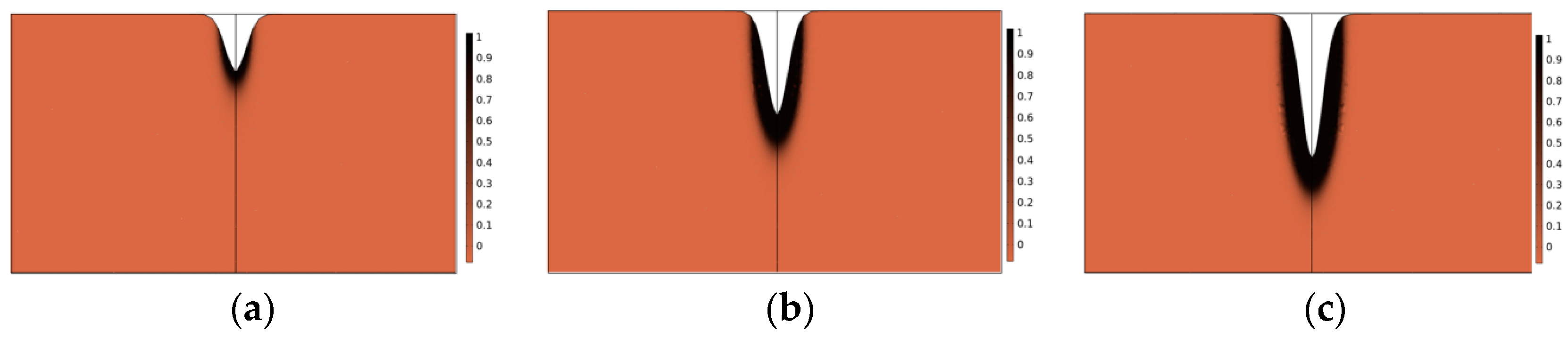
3.3. Influence of Spot Radius on Ablative Damage during Gas-Assisted Laser Processing for Wood

During the gas-assisted laser processing of wood, the laser heat source irradiated by the laser generator had a Gaussian distribution, and its spot size represented the direct irradiation range of its output energy. Therefore, as the spot radius increased, the maximum temperature decreased. This could be due to the concentration of heat generated by a Gaussian beam at the center of the spot; the maximum temperature often reached or exceeded the gasification temperature of the material, and the temperature rapidly decreased with the increased distance from the spot center. When the spot radius increased, the laser beam became relatively dispersed, and the energy density decreased, reducing the highest temperature. To study the influence of different spot radii on wood ablation during gas-assisted laser processing, Scheme b in Table 1 was selected for parameter design, and the temperature field change rule during gas-assisted laser processing was simulated.
Temperature field changes with different spot radii are shown in Figure 5. The spot radius significantly affected the temperature field distribution within the wood. For all spot radii, the temperature growth curve always first increased and then saturated. This could be due to energy accumulation during laser processing, where absorbed energy continuously increases over time, leading to a rapid temperature rise. When the wood completed gasification and ablation reactions under high-temperature irradiation, the ablation damage at the incision reached its maximum, and there was no excess material for heat conduction; at this time, the temperature field was in a stable state. A longitudinal point in time was evaluated; when t = 1 s, the maximum temperature showed a decreasing trend with an increased spot radius during an identical irradiation time. This could be because the total power remained constant: the larger the spot radius, the larger the irradiation area, and the smaller the surface power density. Therefore, less heat was absorbed per unit area on the wood surface, decreasing the temperature value. The spacing between adjacent curves was not equal; because the laser irradiation area was proportional to π r 2 , the temperature field decreased exponentially with an increased spot radius during gas-assisted laser processing.
Ablative damage volume changes with different spot radii are shown in Figure 6. The ablative damage volume of the wood changed into a ray shape with time. A transverse comparison of any given spot radius shows that increased ablative damage volume at t = 0.2 s was significantly smaller than the same spot radius at t = 2 s. This discrepancy arose from longer ablation times, resulting in greater total energy accumulation and, consequently, larger ablation damage volume differences. A longitudinal time point was evaluated when the action time was t = 2 s; the ablative damage volume corresponding to different spot radii is shown in Table 2. The damage volume was about 24.914 mm3 for rd = 50 μm, about 25.17 mm3 for rd = 150 μm, and about 24.958 mm3 for rd = 300 μm. The wood damage volume irregularly changed under different spot radii because it was related to the threshold temperature; damage could occur as long as the temperature exceeded the threshold. Consequently, when the spot radius ranged from 50 μm to 100 μm, due to its diminutive size, the heat source focused on a specific point and irradiated onto the wood surface; the limited contact area prevented effective radial heat transfer and resulted in a significant damage span. As the spot radius increased, the effective laser irradiation area also increased, and the damage span was not obvious at this time. When the wood’s surface temperature and the irradiation area of the laser spot reached a suitable proportional relationship, the ablative damage volume of the wood reached the maximum.
Gasification volume changes with different spot radii are shown in Figure 7. The gasification volume diverged with time in a fan pattern under different spot radii. Due to the transition from the solid phase to the gas phase during the gasification process, the non-linear change caused by the heat absorption of this phase transition resulted in a partial cross-interval during the growth of the gasification volume over time. A transverse comparison of any given spot radius shows that when rd = 200 μm, the increased gasification volume at t = 2 s was significantly greater than at t = 0.2 s; with the accumulation of ablation time, the more laser energy acting on the wood surface, the larger the gasification volume produced. A longitudinal time point was evaluated; when the action time was t = 1 s, the gasification volume was about 0.434 mm3 for rd = 50 μm, about 0.453 mm3 for rd = 150 μm, and about 0.163 mm3 for rd = 300 μm. The gasification volume changed irregularly with an increased spot radius because it was related to the surface area of the laser-irradiated wood and the heat conduction depth. Because the total power of the laser irradiation remained constant, when the spot radius increased, its corresponding action area increased; at the same time, the heat conduction depth decreased owing to heat divergence. Conversely, when the spot radius was small, the corresponding action area was relatively small, but the heat conduction depth increased owing to heat concentration. Therefore, when the same laser energy irradiated the wood, only the appropriate spot radius was selected; thus, the maximum wood gasification volume could be obtained in the cutting process.
Residual carbon black changes with different spot radii are shown in Figure 8. The central white region represents the slit size generated by wood gasification, while the surrounding black area indicates a carbonization area generated by ablation during the heat conduction process. With the increased spot radius, the slit’s width increased, but its depth decreased. The residual carbon black change corresponded to this, but the residual carbon black volume change did not have general regularity.

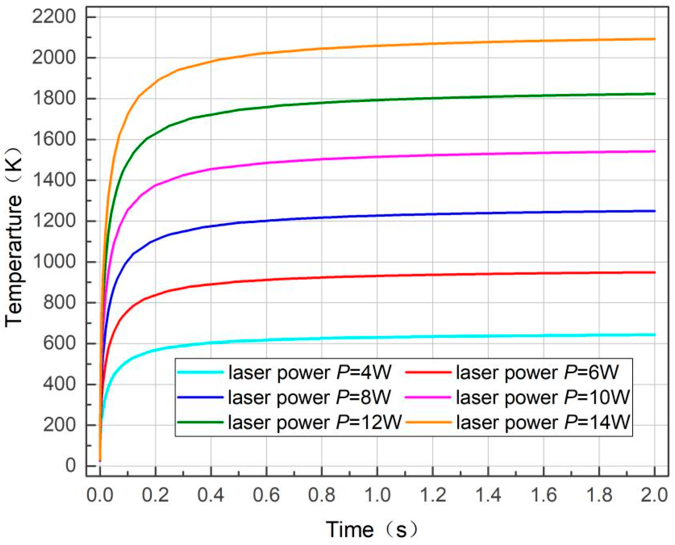
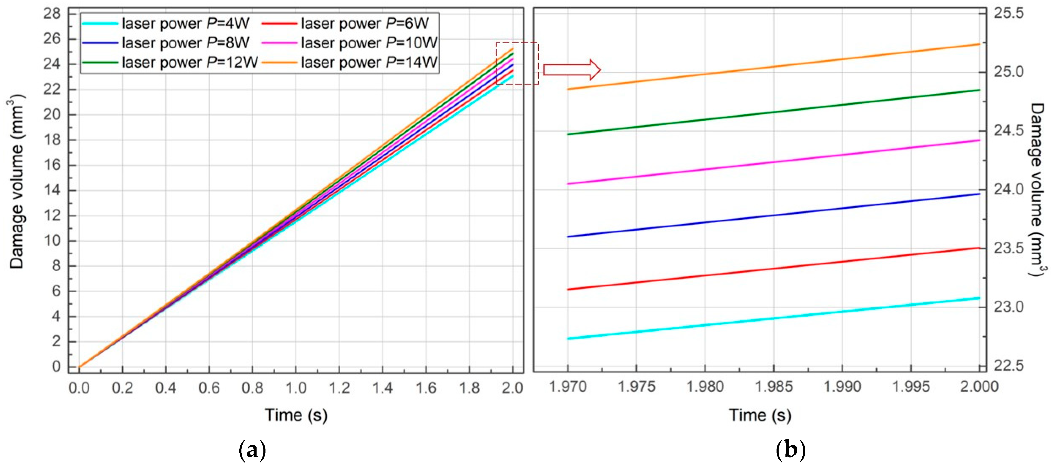
3.4. Influence of Laser Power on Ablative Damage during Gas-Assisted Laser Processing for Wood

Laser power is a crucial parameter in laser processing equipment and significantly influences slit depth, slit width, and cutting quality. Variations in laser power affect heat energy density, directly affecting the temperature field distribution. To investigate the influence of different laser powers on temperature field distribution during gas-assisted laser processing for wood, Scheme c in Table 1 was selected for parameter design, and the temperature field change rule during this process was simulated.
Temperature field distribution changes with different laser powers are shown in Figure 9. Laser power significantly influenced the temperature field, and the center point of the laser action on the wood surface was the highest temperature in the entire cutting area. For all laser powers, the temperature growth curve consistently first increased and then saturated. At the initial laser action stage, heat distribution became more concentrated with time, the energy absorbed by the wood increased continuously, and the temperature rose rapidly. With a prolonged action time, the heat partially dissipated from the system owing to the convection heat transfer caused by auxiliary gas sprayed from the nozzle. Simultaneously, with increased temperature, the surface radiation effect became more prominent, and the whole system partially lost energy owing to the radiation effect. Eventually, when the energy loss caused by radiation and convective heat transfer balanced with the total laser power, the temperature of the entire system reached a stable state and no longer changed with time. A longitudinal time point was evaluated; when the action time was t = 0.6 s, the increased temperature was approximately proportional to the increased laser power, and the intercept between the curves at identical times was the same. This was because laser energy was the primary heat source during wood ablation; in the same period, a higher laser power resulted in higher heat source temperature; thus, the slit temperature increased with the increased heat acting on the wood surface.
Ablative damage volume changes with different laser powers are shown in Figure 10. The damage volume changed with time in a radial pattern under different laser powers, and the divergence became more pronounced. When t = 0, there was no laser energy irradiation; no ablative reaction occurred as the starting point for ablative damage, which did not effectively reflect the influence of laser power on wood damage volume. A transverse comparison of any given laser power shows that the increased damage volume under laser action at t = 0.2 s was significantly smaller than at t = 2 s; the longer the ablation time, the greater total energy accumulation and the larger the difference in damage volume. A longitudinal time point was evaluated; when the action time was t = 1 s, the damage volume was approximately 11.53 mm3 at P = 4 W and about 12.47 mm3 at P = 14 W. Thus, the damage volume increased with the increased laser power at the same time. The difference in the vertical intercept between the adjacent curves was basically the same, showing that the damage volume changed linearly with increased unit power.
Gasification volume changes with different laser powers are shown in Figure 11. The ablative gasification volume changed with time in a fan-divergent under different laser powers. A transverse comparison of any given laser power shows that when the laser power was P = 4 W, the gasification volume remained constant during t = 2 s of laser irradiation. This was because the energy acting on the wood surface was low; in addition to the energy absorbed by the wood surface, the heat conduction to the interior of the slit could not reach the gasification temperature of the wood; thus, the gasification volume was relatively small. When the laser power was P = 14 W, the gasification volume increased rapidly with the ablation time because the initial energy acting on the wood surface was high enough to reach its gasification temperature; therefore, the longer the ablation time, the more total energy accumulation and the greater the gasification volume produced. A longitudinal time point was evaluated; when the action time was t = 1 s, the gasification volume was approximately 0.03 mm3 for P = 4 W and about 0.37 mm3 for P = 14 W. Thus, the gasification volume increased with increased laser power at the same time. The difference in the vertical intercept between the adjacent curves increased multiple times, and the gasification volume changed linearly with the increased unit power. During gas-assisted laser processing, the irradiation energy acting on the wood surface gradually increased, the gasification volume of wood changed significantly, and the wood surface and internal areas that achieved gasification increased; thus, the gasification volume increased.
Residual carbon black changes with different laser powers are shown in Figure 12. When the wood was irradiated by a high-energy laser beam to reach its boiling point and directly gasify, the heat was transferred to the surrounding low-temperature region through a thermal conductivity mechanism. Wood primarily consists of compounds containing carbon (C), hydrogen (H), and oxygen (O); thus, during the heat transfer process, when the temperature drop could not reach the wood gasification condition, combustion occurred at high temperatures, and a carbonization influence zone was generated around the slit. The residual carbon black volume was related to the size of the gasification volume; the larger the laser power and the longer the thermal action time, the greater the residual carbon black volume.

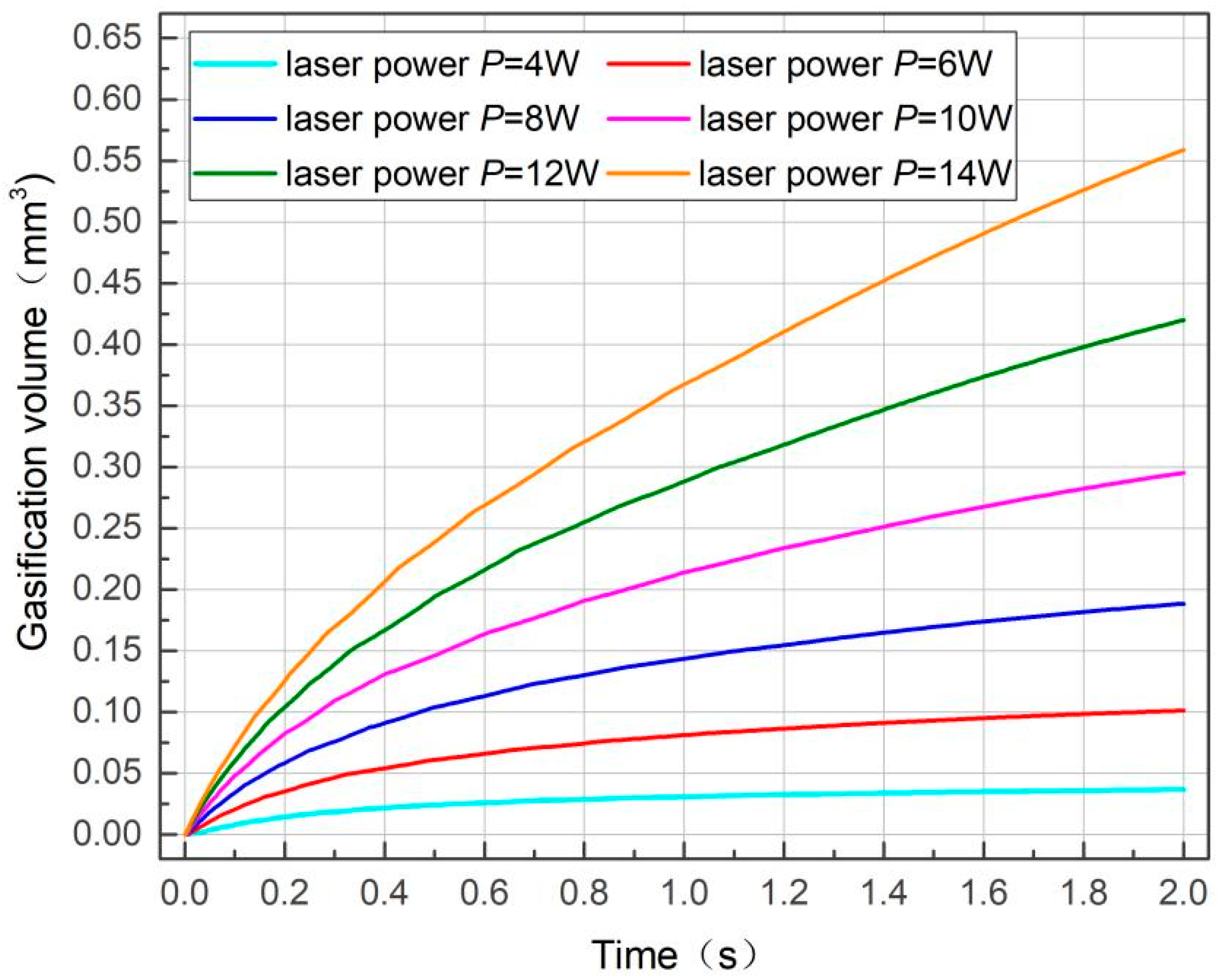
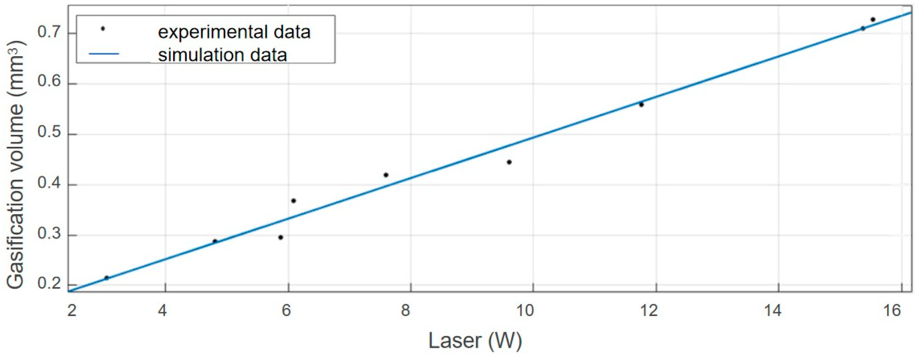
3.5. Verification of the Influence of Laser Power on Wood Gasification Volume

The slit cross-section for gas-assisted laser processing is shown in Figure 13. The actual shape is similar to the calculated one. Using inert gas during cutting reduced heat input and minimized the heat-affected zone, resulting in a gasification area with a wider top and narrower bottom. During the gas-assisted laser processing of wood, the influence of the wood ablation process can be obtained by changing different process parameters. Typically, the spot radius is adjusted before equipment delivery from the factory; thus, the influence of the spot radius on temperature field distribution and ablation damage can only be visually represented through numerical simulation. In contrast, laser power can be manually controlled during laser processing. However, the transient temperature increases during the process and then decreases sharply with laser beam movement, and there can be significant errors in the temperature measurement. The gasification volume generated during the wood ablation process refers to the size of the formed slit, and the actual volume size can be calculated through measurements. Therefore, to verify the accuracy of the simulation results, the gasification volume was used as the reference standard for data fitting. Because the basic shape of seams resembles a cone, we consider the slit width equivalent to the base circle radius and the slit depth equivalent to height in the cone volume formula for measurement and calculation purposes.
A comparison between the experimental and simulation data for gasification volume is shown in Figure 14. The distance between the laser nozzle and the wood surface, h, was 1 mm; gas pressure, Pgas, was 0.1 MPa; and the spot radius, rd, was 250 μm. Experimental measurements of the gasification volume value increased with increased laser power, and were distributed on both sides of the simulated predicted value. The experimental results were basically consistent with the simulation results. The experimental data were fitted and analyzed with the simulation data; the mean square error, R2, was 0.9860; the root mean square error (RMSE) value was 0.0233; and the error term degree of freedom was 7. Furthermore, the predicted value significantly exceeded the critical test value, and the model adjustment determination coefficient was 0.9840. These results demonstrate that the model exhibited excellent fitting performance with minimal testing errors, effectively describing the influence of relevant parameters on the processing quality of gas-assisted laser processing for wood. The data analysis results from the simulation model were highly reliable.
Based on the heat conduction theory, this study establishes a gas-assisted laser processing model using finite element software, helping to accurately control various parameters during the process and reducing processing errors generated by traditional methods, and designs the same experimental parameters to verify the reliability of the simulation results. Combining coupled simulations of heat conduction and gas flow, a more accurate depiction of the mutual influence between laser heating and gas flow was achieved, revealing how gas flow affects the thermal distribution in laser processing. Through virtual environments, the effectiveness of different design schemes can be rapidly evaluated, optimizing parameter settings to mitigate issues such as thermal cracking and deformation caused by thermal effects. In further research, considering the challenges in obtaining experimental data on the dynamic behavior of auxiliary gasses, we will explore multi-scale simulations that analyze the impact of gas flow on heat transfer within fiber gaps and wood pores by combining the macroscopic characteristics of gas flow with the microscopic structures of wood. This will improve our understanding of gas flow behavior for the practical optimization of gas-assisted laser processes through theoretical foundations and technical support.

4. Conclusions

The heat conduction effect during laser processing of wood significantly influences the quality of slit formation. In this study, numerical simulation was carried out to predict the temperature field distribution and ablation damage changes during this process. We found that helium gas assistance has a positive effect on reducing surface temperature and minimizing the heat-affected zone. The simulation results show that, when the spot radius remains constant, the temperature field distribution, ablative damage volume, and gasification volume of the wood increase linearly with increased laser power, indicating that laser power significantly affects the wood slit depth. When the laser power is constant, the temperature field distribution of wood decreases with the increased spot radius, but ablative damage volume and gasification volume change irregularly with the increased spot radius. These variations are mainly related to the irradiation area and the threshold temperature; in particular, the spot radius significantly affected the width of the wood slit. Finally, microscopic experiments were conducted for comparison verification, validating the effectiveness of the data distributed on both sides of the simulated data. This study provides new insights into improving wood treatment processes and enhancing surface smoothness and consistency, positively contributing to promoting sustainable forest management and utilization.

Author Contributions

Conceptualization, Q.L.; methodology, L.N.; software, Q.L.; validation, F.W.; investigation, T.L.; data curation, F.W.; writing—original draft preparation, Q.L. and C.Y.; writing—review and editing, L.N. All authors have read and agreed to the published version of the manuscript.

Funding

This research was funded by Research Start-up Fund Project of Oriented Training (Introduction of Talents) of Heilongjiang Bayi Agricultural University (XYB202205) and Research Start-up Fund Project of Oriented Training (Introduction of Talents) of Heilongjiang Bayi Agricultural University (XDB202205) and Three Vertical Research Support Programs (ZRCPY202202).

Data Availability Statement

Data are contained within the article.

Acknowledgments

We thank Xinchi Tian and Yuan yuan Miao for fruitful discussion on numerical simulation and technical aspects of the measurements.

Conflicts of Interest

The authors declare no conflicts of interest.

Abbreviations

AbbreviationSignificanceUnit
ρwood densitykg/m3
C P specific heat capacity of woodJ/kg·K
k thermal diffusivityW/(m·K)
Q calorific value of internal heat sourceW/m3
u gas flow ratem/s
H 1 enthalpy of phase 1 before phase transitionKJ/mol
H 2 enthalpy of phase 2 after phase transitionKJ/mol
θproportion of pre-transition phase
α T Dirac pulse
H D heat source depthmm
C s concentration coefficient of heat source
R H opening radius of body heat sourcemm
Plaser powerW
rdspot radiusμm
Pgasgas pressureMPa
hdistance between laser nozzle and woodmm
a s damage degree
A frequency factor
R g gas state quantity constant
E activation energyKJ/mol
T k absolute temperatureK

References

  1. Krisztián, B.; Márton, N.; Zs, F.; Attila, S. Comparison of Direct and Indirect Structural Analysis of HAZ after Laser Cutting in Amorphous Alloys. Acta Phys. Pol. A 2020, 137, 861–863. [Google Scholar]
  2. Gao, S.X.; Ding, X.P.; Li, X.H. Research status and prospects of laser cutting technology in China. Mech. Res. Appl. 2024, 1, 173–176. [Google Scholar]
  3. Zhai, W.C.; Yang, B.C.; Liu, Y.H.; Yuan, K.J.; Kong, H.Y.; Song, Y. Development and Status of Laser Surface Processing. Hot Work. Technol. 2017, 56, 38–41. [Google Scholar]
  4. Wang, W.Z.; Hao, X.Q.; Zhou, J.T.; Wei, C.F. Research on laser-assisted micro-milling of composite materials. Tool Eng. 2024, 7, 46–53. [Google Scholar]
  5. Kovalev, O.B.; Yudin, P.V.; Zaitsev, A.V. Modeling of flow separation of assist gas as applied to laser cutting of thick sheet metal. Appl. Math. Model. 2009, 33, 3730–3745. [Google Scholar] [CrossRef]
  6. Chen, Z.W.; Zhang, F.; Zhang, Z.N.; Chen, S.; Li, Y.H.; Zhou, P.R.; Tang, R.X.; Ping, X.F. Water guided laser processing technology and application. Nonferrous Met. Process. 2023, 6, 1–7+40. [Google Scholar]
  7. Yuan, R.; Yang, B.; Ruan, H.Y. Flow Field Analysis of Gas Jets from Nozzles for Gas-Assisted Laser Cutting. Key Eng. Mater. 2010, 419, 409–412. [Google Scholar] [CrossRef]
  8. Darwish, M.; Mrna, L.; Orazi, L.; Reggiani, B. Numerical modeling and schlieren visualization of the gas-assisted laser cutting under various operating stagnation pressures. Int. J. Heat Mass Transf. 2020, 147, 1–11. [Google Scholar] [CrossRef]
  9. Chen, K. Gas Jet–Workpiece Interactions in Laser Machining. J. Biomol. Screen. 2000, 122, 429–438. [Google Scholar] [CrossRef]
  10. Han, Y.J.; Zhu, G.X.; Guo, X.G. Study on Laser Removal and Forming Technology of Wood. For. Mach. Woodwork. Equip. 2002, 10, 16–18. [Google Scholar]
  11. Mukherjee, K.; Grendzwell, T.; Khan, P.; Mcmillin, C. Gas flow parameters in laser cutting of wood-nozzle design. For. Prod. J. 1990, 40, 39–42. [Google Scholar]
  12. Hernandez-Castaneda, J.C.; Sezer, H.K.; Li, L. Dual gas jet-assisted fibre laser blind cutting of dry pine wood by statistical modelling. Int. J. Adv. Manuf. Technol. 2010, 50, 195–206. [Google Scholar] [CrossRef]
  13. Sulaiman, F.A.; Yilbas, B.S.; Karatas, M. CO2 laser cutting of Kevlar laminate: Influence of assisting gas pressure. Int. J. Adv. Manuf. Technol. 2009, 45, 62–70. [Google Scholar] [CrossRef]
  14. Hernandez-Castaneda, J.C.; Sezer, H.K.; Li, L. Single and dual gas jet effect in Ytterbium-doped fibre laser cutting of dry pine wood. Int. J. Adv. Manuf. Technol. 2011, 56, 539–552. [Google Scholar] [CrossRef]
  15. Nukman, Y.; Ismail, S.R.; Azuddin, M.; Aznijar, A. Selected Malaysian Wood CO2-Laser Cutting Parameters and Cut Quality. Am. J. Appl. Sci. 2008, 5, 990–996. [Google Scholar]
  16. Yilbas, B.S.; Shuja, S.Z.; Budair, M.O. Nano-second laser pulse heating and assisting gas jet considerations. Int. J. Mach. Tools Manuf. 2000, 40, 1023–1038. [Google Scholar] [CrossRef]
  17. Yao, J.F.; Yu, M.H.; Zhao, T.; Kawahara, A.; Sadatomi, M. Investigation of CO2 Absorption Performance in a Gas-liquid Two-Phase Flow Atomizer on the Basis of a Gas Diffusion Model. Trans. Can. Soc. Mech. Eng. 2017, 41, 1–11. [Google Scholar] [CrossRef]
  18. Sun, D.W.; Cai, Y.; Li, F.; Hua, X.M. Study on the influence of side assisting gas on energy loss during CO2 laser welding based on 3D reconstruction. Int. J. Adv. Manuf. Technol. 2016, 86, 3417–3426. [Google Scholar] [CrossRef]
  19. Leone, C.; Lopresto, V.; Iorio, I.D. Wood engraving by Q-switched diode-pumped frequency-doubled Nd:YAG green laser. Opt. Lasers Eng. 2009, 47, 161–168. [Google Scholar] [CrossRef]
  20. Lazov, L.; Narica, P.; Valiniks, J.; Pacejs, A.; Deneva, H.; Klavins, D. Optimization of CO2 Laser Parameters for Wood Cutting. Environ. Technol. Resour. Proc. Int. Sci. Pract. Conf. 2017, 3, 168–173. [Google Scholar]
  21. Yang, C.M.; Jiang, T.; Ma, Y.; Li, H.N.; Liu, J.Q. Design and Experimental Study on Water-jet Assisted Nanosecond Laser Equipment for Wood. China For. Prod. Ind. 2019, 46, 12–16. [Google Scholar]
  22. Yu, J.L.; Chen, P. Influence of Inert Gases to Deflagration Flame Quenching. J. Combust. Sci. Technol. 2008, 14, 193–198. [Google Scholar]
  23. Chen, X.H. Experimental Study and Numerical Simulation of Low-Pressure Jet Assisted Laser Etching. Ph.D. Thesis, Nanjing University of Science & Technology, Nanjing, China, 2019. [Google Scholar]
  24. Naderi, N.; Legacey, S.; Chin, S.L. Preliminary investigations of ultrafast intense laser wood processing. For. Prod. J. 1999, 49, 72–76. [Google Scholar]
  25. Arai, T. Simulation of Pulse Laser Welding of a Thin Metal and Comparison with Other Heat Sources. Mater. Werkst. 2013, 44, 462–471. [Google Scholar] [CrossRef]
  26. Ma, Y. Study on Numerical Simulation of General Expression of Double Ellipsoidal Heat Source Model. Master’s Thesis, Hebei University of Technology, Tianjin, China, 2015. [Google Scholar]
  27. Piekarska, W.; Kubiak, M.; Saternus, Z. The Influence of Distance Between Heat Sources in Hybrid Welded Plate on Fusion Zone Geometry. Arch. Foundry Eng. 2011, 11, 181–184. [Google Scholar]
  28. Zimmermann, C.; Lemcke, F.J.; Kabelac, S. Nusselt numbers from numerical investigations of turbulent flow in highly eccentric horizontal annuli. Int. Commun. Heat Mass Transf. 2019, 12, 1–6. [Google Scholar] [CrossRef]
Figure 1. Finite element model of gas-assisted laser processing for wood.
Forests 15 01296 g001
Figure 2. Gas-assisted laser processing equipment.
Forests 15 01296 g002
Figure 3. Damage volume of laser-processed wood with or without gas assistance.
Forests 15 01296 g003
Figure 4. Residual carbon black volume of laser processing wood with or without gas assistance.
Forests 15 01296 g004
Figure 5. Temperature field–time curve with different spot radii (rd).
Forests 15 01296 g005
Figure 6. Change curve of wood ablative damage volume with different spot radii (rd). (a) The general trend of the curve change. (b) The detail values of curve at t = 2 s.
Forests 15 01296 g006
Figure 7. Change curve of wood gasification volume with different spot radii (rd).
Forests 15 01296 g007
Figure 8. Change in residual carbon black of wood with different spot radii (rd). (a) rd = 50 μm, (b) rd = 150 μm, (c) rd = 250 μm.
Forests 15 01296 g008
Figure 9. Temperature field–time curve with different laser powers (P).
Forests 15 01296 g009
Figure 10. Change curve of ablative damage volume in wood with different laser powers (P). (a) The general trend of the curve change. (b) The detail values of curve at t = 2 s.
Forests 15 01296 g010
Figure 11. Change curve of wood gasification volume with different laser powers (P).
Forests 15 01296 g011
Figure 12. Changes in residual carbon black of wood with different laser powers (P). (a) P = 4 W, (b) P = 8 W, (c) P = 12 W.
Forests 15 01296 g012
Figure 13. Schematic diagram of slit geometry parameters.
Forests 15 01296 g013
Figure 14. Comparison between experimental data and simulation results for gasification volume.
Forests 15 01296 g014
Table 1. Design of relevant parameters for numerical simulation.
SchemeLaser Power
P (W)
Spot Radius
rd (μm)
Gas Pressure
Pgas (MPa)
Distance between Laser Nozzle and Wood
h (mm)
a122500.11
0
b1250/100/150/200/250/3000.11
c4/6/8/10/12/142500.11
Table 2. Ablative damage volume of wood with different spot radii (rd).
Spot Radius (μm)50100150200250300
Damage volume (mm3)24.91425.13525.1725.15125.07724.958
Disclaimer/Publisher’s Note: The statements, opinions and data contained in all publications are solely those of the individual author(s) and contributor(s) and not of MDPI and/or the editor(s). MDPI and/or the editor(s) disclaim responsibility for any injury to people or property resulting from any ideas, methods, instructions or products referred to in the content.

